《图像处理》实验指导书
《数字图像处理》实验指导书(2011年用过)

《数字图像处理》实验指导书实验一、图象的基本操作(2学时)实验二、图像的傅立叶变换(2学时)实验三、图像增强(2学时)实验四、图像压缩(2学时)实验五、图像融合(选做)实验一图像的基本操作1.实验目的熟悉常用的图像文件格式与格式转换;熟悉图像矩阵的显示方法(灰度、索引、黑白、彩色);熟悉图像矩阵的格式转换使学生熟悉图象文件格式、图象的载入、彩色图象的构成、图象的显示等。
2.实验内容练习图像读写命令 imread和imwrite并进行图像文件格式间的转换。
特别是索引图像与1,4,8,16 比特图像的存储与转换。
Image file I/O.imread - Read image file.imwrite - Write image file.Image display.colorbar - Display colorbar.getimage - Get image data from axes.image - Create and display imageimagesc - Scale data and display as image.immovie - Make movie from multiframeimage.imshow - Display image.subimage- Display multiple images in single figure.truesize - Adjust display size of image.warp - Display image as texture-mapped surface.zoom - Zoom in and out of image or 2-D plot.3.实验步骤a. 从硬盘加载 cameraman.tif 图象 (用函数 imread).b. 在图象显示窗口显示图象 (using function image or imshow).c. 显示彩色图象的 3 基色图象。
《数字图像处理》实验指导书1

《数字图像处理》实验指导书前言本实验指导书可作为电子信息工程、通信工程、生物医学工程等专业《数字图像处理》课程的实验指导书。
实验指导书共提供了6个实验,要求在VB环境下实现。
实验名称与学时安排详见下表。
实验名称与学时安排表实验教学基本要求:1、在实验前,认真准备,熟悉和掌握相关实验内容的基本算法和程序设计技术。
2、根据实验目的和要求,按时认真完成各实验的上机操作。
3、实验结束后,要及时提交经调试正确的程序源代码、生成的可执行文件、实验报告书等文档。
实验一图象的读取保存及图像的二值化处理一、实验目的1、熟悉《数字图像处理》的实验平台。
2、了解VB对图像进行处理的基本方法。
3、熟悉彩色图像变成灰度图象以及灰度图像转换成二值图像的基本原理及处理过程。
二、实验准备1、复习彩色图像变成灰度图象以及灰度图像的二值化处理的基本原理。
2、阅读下列内容,了解VB对图像进行处理的基本方法。
(1)读取图像通过扫描仪、摄像机等输入计算机以.bmp、.ico或.wmf存储的图像文件,可用LoadPicture函数把图像文件装入窗体、图片框或图像框中,例如:picture1.picture=loadpicture(“c:\image\flower.bmp”)可以把路径为c:\image\flower.bmp的图像文件装入图片框picture1中。
为了使图片框的大小与图像相匹配,应将图片框的autosize属性设置为True。
(2)用Point方法获取彩色图像的颜色值Point方法的功能是获取图像上指定像素的颜色值。
格式为:Object.Point(x,y)其中,Object表示获取颜色的对象名,(x,y)为取得颜色的坐标位置。
Point 方法将指定位置的像素的颜色值返回一个长整形数。
例如,求图片框picture 1中图像在位置(x,y)的像素颜色值(col)时,可写为:dim col as longcol=picture1.Point(x,y)(3)用Pset方法画点Pset方法的功能是在指定的位置画一个指定颜色的点。
《计算机图像处理》实验指导书

《计算机图像处理》实验指导书适用专业:计算机科学与技术专业,网络工程专业2014年春季学期实验目的:通过实验,使学生能够在所学的计算机图像处理理论指导下,应用Matlab图像处理软件编写有关程序,熟悉并掌握图像数据的输入与输出、图像灰度变换、图像增强、图像分割等基本处理技术,巩固有关知识内容,提高实际动手能力,为进一步的应用和解决实际问题奠定基础。
实验要求:实验内容必须由本人独立完成,通过对实验题目的分析和实现,给出实验结果,并进行相关的说明。
实验过程一般经历以下三个阶段:1.上机前的准备针对实验问题,熟悉Matlab开发环境,通过分析选择适当的方法,探讨可能遇到的问题及解决的对策。
准备有关的程序流图、测试程序的图像数据,并预测其处理结果。
2.程序的编辑、调试和运行利用Matlab集成开发环境,输入并编辑好源程序,然后进行程序的调试,使用预先准备的测试图像运行程序,观察是否得到了预期的结果。
若有问题,仔细排除各种错误,直到得到满意的实验结果。
3.整理实验结果,撰写实验报告实验结束后,及时整理实验结果并认真分析和总结,撰写实验报告。
在实验报告中需写明每个实验的具体实现步骤;源程序代码以及必要的注释;所用到的图像数据和运行结果截图;对实验结果的说明和分析;调试过程中遇到的问题及解决办法;分析不足之处及改进方法等。
注意事项:1.每个同学上交一份实验报告,不接受不完整的实验报告,或者说明与程序和实验结果不符合的实验报告。
2.实验报告在最后一次上机后提交,实验报告电子版文件的命名格式:学号_姓名.doc。
3.实验成绩考核的内容包括学生出勤情况、实验态度、完成质量、成果展示和实验报告等,分为优、良、中、及格和不及格五个等级。
实验一 MATLAB数字图像处理基本操作一、实验目的与要求1.熟悉MA TLAB软件的开发环境、基本操作以及图像处理工具箱,为编写图像处理程序奠定基础。
2.掌握二值、灰度和彩色图像的读、写和显示方法,以及图像的高、宽、颜色等参数的获取方法。
图像处理实验任务书2011版

图像处理实验任务书2011版《图像处理》实验指导书10学时指导教师:蒋旻、付晓薇实验报告要求1、做好实验相关预习⼯作,了解实验的⽬的与内容。
每次实验报告中,⾸先写清实验⽬的。
然后,写出实验内容中的题⽬、程序清单(加上必要注释)、程序运⾏结果 (可将图像处理效果图附在实验报告中;对综合应⽤性较⾼的题⽬,要求在给出代码前,绘制算法设计的流程图)。
最后,给出100字以内的实验体会或总结。
要求必须写在实验报告中,图⽚效果可以剪贴到报告册上。
每次实验报告⾸页页眉写上实验时间、指导⽼师姓名。
2、实验报告要求⼿写在实验报告册中,请勿打印。
实验⼀Matlab图像显⽰与图像运算(2学时)【实验⽬的】1、熟悉Matlab的编程环境及其基本⽤法;2、掌握MATLAB语⾔中图像数据与信息的读取⽅法;了解m⽂件的编写与调试⽅法;3、熟悉图像点运算和代数运算的实现⽅法;4、掌握Matlab图像⼏何变换的基本函数;5、了解图像⼏何运算的简单应⽤;【实验内容】1、IntroductionIn the following we give a short overview on a very limited set of basic image processing functions provided by MATLAB. The function descriptions only cover the basic usage, more detailed information can be found in the manual pages by typing doc functionName at the MATLAB command line. MATLAB provides with it’s im age processing toolbox many powerful and very efficient image processing functions (see function list of the image processing toolbox). With this it is very simple to implement complex image processing applications, especially for fast prototyping. On the backside, a lot of understanding how image processing works is hidden within black boxes and temps to make things more complicate than they really are. 2、Image representationIn MATLAB a binary and gray-scale image is represented by one 2-dimensional array, whereas a color image are represented by a 3-dimensional array (one 2-dimensional array for each of the color planes or color channels red, green and blue):The origin of the image is in the upper left and the size of the image is defined by the parameter width (number of columns of the array) and height (number of rows of the array). Note that the x- and y-coordinates are chosen such that the z-axis points to the front.A single point within the image is called pixel. A gray-scale or binary pixel consists of one data value, a color pixel consists of3 data values (each for one of the color channels). The most common data types of the individual pixels are:uint8 unsigned integer: data range 0..255double double precision float: data range 0.0 ... 1.0Bi nary images have pixel values of 0’s and 1’s resp. 0.0 and 1.0. In the case of uint8 images, the logical flag must be turned on, to be recognized as binary image (for details see below).Be careful with data types in MATLAB. Many of the predefined functions, e.g. imadd(img1, img2) which adds two images, just truncates data values to 255 on uint8-arrays ... make sure if that is what you want.Hints:To avoid problems with data types, especially when working with predefined image processing functions, it is advisory to work with type double and make sure that data is scaled to the range 0 ...1.0.3、Basic MATLAB functions3.1 MATLAB manualdoc functionname displays the manual for the MATLAB function functionnamedoc images the manual for the image processing toolboxdoc imaq the manual for the image acquisition toolbox3.2 Image informationimfinfo(’foo.ext’)displays information on image format etc. of the file foo.extimformats displays an overview of all MATLAB image formatswhos img displays information about the array img: size, data type, etc.3.3 Reading, writing and displaying imagesmyImg = imread(’foo.ext’)reads file foo.ext into array myImg, image format is determined bythe file extension (jpg, tiff, tif, gif, bmp, png, ...)imwrite(anImg, ’foo.ext’)writes the image anImg to the file foo.ext, where the image format ischosen according to the extension ext. Valid extensions are: tif, tiff,jpg, jpeg, gif, pngimshow(myImg) displays the image myImg as gray-scale, binary or color image depending on the data type of myImg imshow(myImg,[]) the image myImg as gray-scale, binary or color image depending onthe data type of myImg and scales the image properlyfigure(n) opens a new window with number n, the next call to imshow()displays the image within this window3.4 Basic image processing functionsislogical(binImg) checks whether array binImg has the logical flag set or not(returns value 1 or 0)img = uint8(zeros(512,1024)) creates a black image with width 1024 and height 512 of typeuint8img = uint8(255*ones(512,1024)) creates a white image with width 1024 and height 512 of typeuint8img = double(zeros(512,1024)) creates a black image with width 1024 and height 512 oftype doubleimg = double(ones(512,1024)) creates a white image with width 1024 and height 512 oftype double[height width d] = size(myImg) retrieves height and width and stores the values invariables height and width, d ist set to the arraydimension.red = myImg(:,:,1) stores the red component of myImg (rgb-image) in array red green = myImg(:,:,2) stores the red component of myImg in array greenblue = myImg(:,:,3) stores the red component of myImg in array bluemx = max(myImg(:))) computes the maximum value of an 2-d arraymi = min(myImg(:))) computes the minimum value of an 2-d arrayimg = double(myImg)/255 converts an uint8 array to a double array (no scaling) img = double(myImg)/double(mx) converts uint8 to double and scales maximum to 1.0i mg = uint8(anImg*255) converts a double array to an unit8 array and rescales thearray to the proper data rangebw = logical(binImg) sets the logical flag on the unit8 array binImg (data values0 and 1), array bw is then interpreted as a black and whiteimage and logical operations can be appliedgray = (+bw)*255 turns the logical flag off and rescales the array bw to bedisplayed as unit8 array3.5 Examples3.5.1 Scaling imagesThe following two statements scale a double type image to the range 0.0 ... 1.0. This is important, when the image contains negative pixel values, as e.g. after applying edge detection algorithms.f = f - min(f(:));f = f / max(f(:));3.5.2 Color planesThe green and red color plane of image rgbimage.jpg are swapped:f = imread(’rgbimage.jpg’);red = f(:,:,1);g(:,:,1) = f(:,:,2);g(:,:,2) = red;g(:,:,3) = f(:,:,3);imshow(g);3.5.3 Individual pixel processingThe intensity of the red color channel of rgbImage.jpg is divided by 2.f = imread(’rgbImage.jpg’);[M N d] = size(f);g = unint8(zeros(M,N,3));for x = 1:Mfor y = 1:Ng(x,y,1) = f(x,y,1) / 2;g(x,y,2) = f(x,y,2);g(x,y,3) = f(x,y,3);end;end;imshow(g);Using the MATLAB array notation, this may be written as:f = imread(’rgbImage.jpg’);g = f;g(:,:,1) = g(:,:,1) / 2;imshow(g);The image color image rgbImage.jpg is converted to a grayscale image, by simply computing the mean of the three color channels (one possible method) and then stored in file grayImage.jpg. Note that the quality of the resulting image is set to 100 (no data loss):f = imread(’rgbImage.jpg’);[M N d] = size(f);g = unint8(zeros(M,N));for x = 1:Mfor y = 1:Ng(x,y) = (f(x,y,1) + f(x,y,2) + f(x,y,3)) / 3;% The line above doesn’t work.% Overflow occurs, while processing uint8, because% the value range in the intermediate results are limited to 255g(x,y) = (f(x,y,1)/3 + f(x,y,2)/3 + f(x,y,3)/3);end;end;imshow(g);imwrite(g, ’grayImage.jpg’, ’Quality’, 100);Using the MATLAB array notation, this may be written as:f = imread(’rgbImage.jpg’);g = uint8(mean(f,3));imshow(g);imwrite(g, ’grayImage.jpg’, ’Quality’, 100);The image grayImage.jpg is slightly blurred by computing the mean of a 3x3 pixel environment and by setting the resulting center pixel to this mean value:f = imread(’grayImage.jpg’);[M N d] = size(f);g = unint8(zeros(M,N));for x = 2:M-1for y = 2:N-1sum = f(x-1,j-1) + f(x-1,j) + f(x-1,y+1);sum = sum + f(x,y-1) + f(x,y) + f(x,y+1);sum = sum + f(x+1,y-1) + f(x+1,y) f(x+1,y+1);rImg(x,y) = unint8(sum/9);end;end;imshow(g);The same functionality could be achieved, by using MATLAB’s powerful image processing functions and in addition avoids the boundary problem:f = imread(’grayImage.jpg’);h = fspecial(’average’,3)g = imfilter(f, h, ’replicate’);imshow(g);4、上机编程题思考题4.1 读⼊图像‘rice.tif’,通过图像点运算改变对⽐度。
《数字图像处理》实验指导书

数字图像处理实验指导书电气信息工程系实验中心2008年8月目 录实验一、数字图像获取实验二、图像的傅立叶变换实验三、图像增强实验四、图像压缩实验一、数字图像获取一、实验目的1.掌握使用扫描仪等数字化设备以及计算机获取数字图像的方法;2.修改图像的存储格式。
二、实验仪器1.计算机;2.扫描仪(或数码相机、数字摄像机)及其驱动程序盘;3.图像处理软件(画图,photoshop, Microsoft photo edit等);4.记录用的笔、纸。
三、 实验内容用扫描仪获取图像也是图像的数字化过程的方法之一,扫描仪按种类可以分为手持扫描仪,台式扫描仪和滚筒式扫描仪(鼓形扫描仪)。
扫描仪的主要性能指标有x、y方向的分辨率、色彩分辨率(色彩位数)、扫描幅面和接口方式等。
各类扫描仪都标明了它的光学分辨率和最大分辨率。
分辨率的单位是dpi,dpi是英文Dot Per Inch的缩写,意思是每英寸的像素点数。
扫描仪工作时,首先由光源将光线照在欲输入的图稿上,产生表示图像特征的反射光(反射稿)或透射光(透射稿)。
光学系统采集这些光线,将其聚焦在CCD上,由CCD将光信号转换为电信号,然后由电路部分对这些信号进行A/D转换及处理,产生对应的数字信号输送给计算机。
当机械传动机构在控制电路的控制下,带动装有光学系统和CCD的扫描头与图稿进行相对运动,将图稿全部扫描一遍,一幅完整的图像就输入到计算机中去了。
图1.1扫描仪的工作原理扫描仪扫描图像的步骤是:首先将欲扫描的原稿正面朝下铺在扫描仪的玻璃板上,原稿可以是文字稿件或者图纸照片;然后启动扫描仪驱动程序后,安装在扫描仪内部的可移动光源开始扫描原稿。
为了均匀照亮稿件,扫描仪光源为长条形,并沿y方向扫过整个原稿;照射到原稿上的光线经反射后穿过一个很窄的缝隙,形成沿x方向的光带,又经过一组反光镜,由光学透镜聚焦并进入分光镜,经过棱镜和红绿蓝三色滤色镜得到的RGB三条彩色光带分别照到各自的CCD上,CCD将RGB光带转变为模拟电子信号,此信号又被A/D变换器转变为数字电子信号。
图象处理实验指导书终

实验一图像变换(验证性)1.实验目的熟悉图像的二维离散余弦变换和反变换;熟悉图像的二维离散傅立叶变换和反变换;2.实验内容图像的二维离散余弦变换和反变换及二维离散傅立叶变换和反变换熟悉下列模块函数:rgb2gray - Convert RGB image or colormap to grayscale.uint8 -Convert to unsigned 8-bit integer.dct2 - Compute 2-D discrete cosine transform.idct2 - Compute 2-D inverse discrete cosine transform.fft2 -Two-dimensional discrete Fourier Transformfftshift - Shift zero-frequency component to center of spectrumifftshift - Inverse fftshiftifft2 - Two-dimensional inverse discrete Fourier transform3.原理傅立叶变换是对线性系统进行分析的一个有力工具,它将图像从空域变换到频域,是我们能够定量地分析诸如数字化系统、采样点、电子放大器、卷积滤波器、噪声、显示点等的作用(效应)。
把傅立叶变换的理论同其物理解释相结合,将有助于解决大多数图像处理问题。
在数字图像处理中,输入图像和输出图像通常都是二维的,一般表示成二维数字矩阵,因此,这里直接讨论二维傅立叶变换、二维DFT、二维FFT。
二维M×N的DFT变换和逆DFT变换分别定义如下∑∑-=-=--=101)/2()/2(),(),(M i N k nk N j mi M j e e k i f n m F ππ其中,m=0,1,…,M-1;n=0,1,…,N-1。
∑∑-=-==1010)/2()/2(),(1),(M m N n nk N j miM j e en m F NMk i f ππ其中,m=0,1,…,M-1;n=0,1,…,N-1。
图像处理实验指导书

第一章系统介绍一.系统概述图像处理开发套件II是基于TMS320C6000数字信号处理器的图像/视频处理算法的开发平台。
同时还是可以集成各种图像/视频处理应用方面的相关设备。
采用该系统提供的硬件和软件,可以完成彩色/黑白图象的实时采集、显示和处理,将现有的算法转换为相应的应用,并在TMS320C6000数字信号处理器上实现,通过采集和显示终端来评估算法的效果。
该系统除了标准规范的高性能硬件外,同时提供常用的图像处理算法实例,提供良好的应用实例。
本系统应用于图象算法处理课程实验,也可应用于图象处理、图象识别、监控等场合。
二.系统构成和主要性能指标图象处理开发套件II由TMS320C6713DSK、视频板、实验箱、软件算法包、附件构成。
1.2.1 TMS320C6713DSK介绍TMS320C6713DSK套件(以下简称6713DSK),包括一块6713DSK板、+5V稳压电源、USB 电缆、光盘。
图1.1 6713DSK板原理框图6713DSK是一款具有高性能价格比的开发应用板卡。
板上采用高性能浮点数字信号处理器TMS320C6713,并集成了USB2.0仿真器。
1.2.2 视频板介绍该视频板主要基于TMS320C6000、C5000数字信号处理器开发设计。
信号接口完全和C6000、C5000应用板卡兼容,并和TI公司的EVM、DSK板兼容。
可以和C6000、C5000板卡结合完成图象处理,也可以独立使用。
完成视频信号采集、显示、处理。
●前端解码芯片:SAA7111●后端编码芯片:AL250●在线可编程大容量FPGA:逻辑时序控制,SDRAM控制,数据读写逻辑;●扩展SDRAM存储器,暂存图象●与TI公司TMS320C6713 DSK处理板接口● +5V 单电源供电图1.2 视频板功能框图图1.3 视频板接口示意图SW —电源开关 CON3—电源输入插口注意:单独使用时需+5V 稳压电源从CON3插件供电,这时开关SW3打到内侧, 当和TMS320C 6713 DSK 配合使用时,不需外部供电,这时将开关SW3外侧。
图像处理实验指导书(英文)

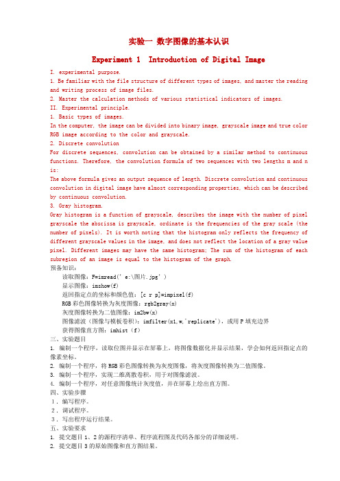
实验一数字图像的基本认识Experiment 1 Introduction of Digital ImageI. experimental purpose.1. Be familiar with the file structure of different types of images, and master the reading and writing process of image files.2. Master the calculation methods of various statistical indicators of images.II. Experimental principle.1. Basic types of images.In the computer, the image can be divided into binary image, grayscale image and true color RGB image according to the color and grayscale.2. Discrete convolutionFor discrete sequences, convolution can be obtained by a similar method to continuous functions. Therefore, the convolution formula of two sequences with two lengths m and n is:The above formula gives an output sequence of length. Discrete convolution and continuous convolution in digital image have almost corresponding properties, which can be described by continuous convolution.3. Gray histogram.Gray histogram is a function of grayscale, describes the image with the number of pixel grayscale the abscissa is grayscale, ordinate is the frequencies of the gray scale (the number of pixels). It is worth noting that the histogram only reflects the frequency of different grayscale values in the image, and does not reflect the location of a gray value pixel. Different images may have the same histogram; The sum of the histogram of each subregion of an image is equal to the histogram of the graph.预备知识:读取图像:F=imread(’e:\图片.jpg’)显示图像:imshow(f)返回指定点的坐标和颜色值:[c r p]=impixel(f)RGB彩色图像转换为灰度图像:rgb2gray(x)灰度图像转换为二值图像:im2bw(x)图像滤波(图像与模板卷积):imfilter(x1,w,'replicate'),或用P填充边界获得图像直方图:imhist(f)三、实验题目1. 编制一个程序,读取位图并显示在屏幕上,将图像数据化并显示结果,学会如何返回指定点的像素坐标。
- 1、下载文档前请自行甄别文档内容的完整性,平台不提供额外的编辑、内容补充、找答案等附加服务。
- 2、"仅部分预览"的文档,不可在线预览部分如存在完整性等问题,可反馈申请退款(可完整预览的文档不适用该条件!)。
- 3、如文档侵犯您的权益,请联系客服反馈,我们会尽快为您处理(人工客服工作时间:9:00-18:30)。
现场考核(60%)+实验报告(40%)
七、实验报告
实验结束后,撰写实验报告,实验报告主题部分应包括:算法原理、程序流程、算法各部分主 要函数代码以及功能注释、运行结果四部分,每部分占实验报告的 10%,按照撰写情况打分。
《图像处理》实验二 图像增强பைடு நூலகம்
一、实验意义及目的
(1)进一步掌握图像处理工具 Matlab,熟悉基于 Matlab 的图像处理函数。 (2)掌握各种图像增强方法。
功能:实现两幅图像相除。
调用格式:
C=imdivide(A,B)。
四、参考代码
参考代码中实现了彩色图像的灰度化、旋转、缩放两种几何变换以及镜像及拼接。
Image1=imread('peppers.jpg'); %红绿通道互换 Image2=Image1; Image2(:,:,1)=Image1(:,:,2); Image2(:,:,2)=Image1(:,:,1); imshow(Image2); imwrite(Image2,'changecolor.jpg');
《图像处理》实验指导书
蔡利梅 编
信息与电气工程学院
学生实验守则
一、学生进入实验室必须遵守实验室的规章制度,遵守课堂纪律,保持实验室的安静和整洁,爱护 实验室的一切设施。 二、实验课前要认真预习实验指导书,写出实验预习报告,并经教师批阅后方可进行实验。 三、实验课中要遵守操作规程,不要带电连接、更改或拆除线路。线路接好后,经指导老师检查后, 方可接通电源进行实验。对于软件上机实验,不得随意删改计算机中原有的文件。 四、学生实验前对实验所用仪器设备要了解其操作规程和使用方法,凡因不预习或不按使用方法进 行操作而造成仪器设备损坏者,除书面检查外,按学校规定进行赔偿。 五、实验中主意安全,遇到事故应立即关断电源并报告教师检查处理。 六、实验完毕后要做好整理工作,实验数据必须经指导教师签阅后,才能拆除线路,并将仪器、设 备、凳子等按规定放好,经同意后方可离开实验室。 七、因故缺课的学生可向实验室申请一次补做机会。无故缺课或无故迟到(15 分钟以上)的不予补 做,该次实验无成绩;累计三次者,该实验课以不及格论,并不得参加该门理论课程的考试。 八、实验室仪器设备不能擅自搬动调换,更不能擅自带出实验室。
%灰度化 gray=rgb2gray(Image1); figure; subplot(121),imshow(Image1),title('Original Image'); subplot(122),imshow(gray),title('Gray Image'); imwrite(gray,'grayimage.jpg');
信息与电气工程学院专业实验中心 二〇一五年三月
《图像处理》实验一 图像色彩、代数、几何变换
一、实验意义及目的
(1)了解和掌握图像处理工具 Matlab,熟悉基于 Matlab 的图像处理函数,并为下一步编程进 行图像处理打下基础。
(2)理解色彩的概念,掌握图像代数运算,几何变换方法。
二、实验内容
打开一幅彩色图像 Image1,使用 Matlab 图像处理函数,对其进行下列变换: (1)将 Image1 红绿色彩互换,并显示效果; (2)将 Image1 灰度化为 gray,并显示灰度化后图像; (3)采用不同的插值方法实现 gray 的旋转、放大变换; (4)打开另一幅彩色图像 Image2,和 Image1 进行代数运算,要求运用拼接、加减乘除等多种 技术。
%图像旋转 Newgray1=imrotate(gray,15); Newgray2=imrotate(gray,15,'bilinear'); figure; subplot(121),imshow(Newgray1),title('旋转15°(最邻近插值)'); subplot(122),imshow(Newgray2),title('旋转15°(双线性插值)'); imwrite(Newgray1,'rotate1.jpg'); imwrite(Newgray2,'rotate2.jpg');
二、实验内容
打开一幅彩色图像 Image1,使用 Matlab 图像处理函数,对其进行下列变换: (1)将 Image1 灰度化为 gray,统计并显示其灰度直方图; (2)对 gray 进行分段线性变换; (3)对 gray 进行直方图均衡化; (4)对 gray 进行伪彩色增强; (5)对 gray 添加噪声并平滑; (6)对 gray 利用 Sobel 算子锐化。
调用格式: imwrite(A,’filename’,fmt):A 是要保存的图像数据矩阵,filename 是文件名,fmt 是文件格式。 imwrite(X,map,’filename’,fmt):X 为索引图像的数据矩阵,map 为其颜色映射表。 (4)rgb2gray 函数 功能:彩色图像灰度化。 调用格式: I = rgb2gray(RGB):真彩色 RGB 图像变换为灰度图像 I。 NEWMAP = rgb2gray(MAP):变换索引图像的调色板为灰度调色板。 (5)imrotate 函数 功能:实现图像旋转。 调用格式: B = imrotate(A,ANGLE,METHOD,BBOX):A 为要进行旋转的图像;ANGLE 为要旋转的角度(°) 逆时针为正,顺时针为负;METHOD 为图像旋转插值方法,可取“'nearest', 'bilinear', 'bicubic'”,默 认为 nearest;BBOX 指定返回图像大小,可取“crop”,输出图像 B 与输入图像 A 具有相同的大小, 对旋转图像进行剪切以满足要求;可取“loose”,默认是,B 包含整个旋转后的图像。 (6)imresize 函数 功能:实现图像缩放。 调用格式: B = imresize(A, SCALE,METHOD)):返回原图 A 的 SCALE 倍大小图像 B; B = imresize(A, [NUMROWS NUMCOLS], METHOD)):对原图 A 进行比例缩放,返回图像 B 的 行数 NUMROWS 和列数 NUMCOLS,如果二者为 NaN,表明 Matlab 自动调整了图像的缩放比例; [Y, NEWMAP] = imresize(X, MAP, SCALE, METHOD)):对索引图像进行成比例缩放。 (7)imtransform 函数 功能:实现图像几何变换。 调用格式: B = imtransform(A,TFORM,INTERP,param1,val1,param2,val2,…) :对图像 A 实现空间变换, TFORM 为 maketform 函数或 cp2tform 函数产生的结构;INTERP 为插值方法,可取“'nearest', 'bilinear', 'bicubic'”。 T = maketform(TRANSFORMTYPE,...):产生转换结构;TRANSFORMTYPE 为变换类型,可以 为“'affine', 'projective', 'custom', 'box', 'composite'”。
(8)fliplr 函数 B=fliplr(X):实现二维矩阵 X 沿垂直轴的左右翻转; (9)flipud 函数 B= flipud(X):实现二维矩阵 X 上下翻转; (10)flipdim 函数 B=flipdim(X,DIM):使矩阵 X 按特定轴翻转,dim 指定翻转方式:为 1 表示按行翻转;为 2 表 示按列翻转; (11)permute 函数 B = permute(A,ORDER):按照向量 ORDER 指定的顺序重排 A 的各维,B 中元素和 A 中元素完全 相同,但在 A、B 访问同一个元素使用的下标不一样。order 中的元素必须各不相同。 (12)imadd 函数 功能:实现两幅图像相加。 调用格式: C=imadd(A,B)。 1)A、B 均为图像,则要求 B 和 A 的尺寸相等;若 B 是一个标量,则 C 表示对图像 A 整体加 上某个值(对小数部分取整)。 2)假如 A 和 B 对应运算和大于 255,C 仍取 255,即截断处理;为避免截断,可以将 C 存储为 uint16,即 C=imadd(A,B,’uint16’)。
%图像镜像与拼接 Image2=imread('lotus.bmp'); HImage=flipdim(Image2,2); VImage=flipdim(Image2,1); CImage=flipdim(HImage,1); [h w]=size(Image2); NewImage=zeros(h*2,w*2,3); NewImage=[Image2 HImage;VImage CImage];
figure,imshow(NewImage); imwrite(NewImage,'newlotus.jpg');
程序的运行效果如下:
peppers.jpg 和 lotus.bmp 为 Matlab 目录下的图像文件。
五、实验要求
1.熟悉 Matlab 函数,读懂参考代码; 2.对彩色图像进行灰度化后,不采用 Matlab 函数,自行设计基于双线性插值的图像放大程序;
(13)imsubtract 函数 功能:实现两幅图像相减。 调用格式: C=imsubtract(A,B):差值结果小于 0 的赋值为 0,对 A、B 的要求同 imadd 相同。 C=imabsdiff(A,B):差值结果取绝对值。
(14)immultiply 函数 功能:实现两幅图像相乘。 调用格式: C=immultiply(A,B):对 A、B 的要求同 imadd 相同;A、B 的乘积通常会超出 uint8 类型的最大 值,一般在应用前把图像类型转化为 uint16。 (15)imdivide 函数
