HPDL360G7服务器安装说明
HPDLG精选服务器安装演示
H P P r o L i a n t D L580G5服务器r a i d创建与2003的安装一、RAID的创建(无图解)1、创建RAID前确定硬盘已经装入服务器。
2、启动服务器,当出现smartarray p400红色提示时,按F8键进入RAID配置主菜单,出现三项子菜单,第一项创建RAID,第二项浏览所创建的RAID,第三项保存退出。
3、选择第一项创建RAID,进入RAID创建界面后,分三步走,第一步选定要创建RAID的硬盘(选定标记为[X]),第二步按Tab键使光标移动到所要创建的RAID(按上下箭头键选择要创建的RAID,如:RAID0,RAID1,RAID5,选定标记为[X]),第三步选择支持的内存大小,按Tab键将光标移动到选择内存大小的地方,按上下箭头键选择8G,选定标记为[X],按Enter键创建RAID,直至完成。
4、选择第二项浏览创建的RAID,看RAID是否创建成功,如果显示为OK字样,则表示RAID创建成功。
5、按ESC键保存退出,按ESC键退出重启服务器。
二、server2003的安装HP服务器可以安装UNIX、linux、windows等操作系统,无论安装什么操作系统,但安装方法基本相似。
这里我们以安装2003为例:HP300\500\700系列服器随设备都会携带引导光盘(SMARTSTARTCD),该光盘可以引导安装操作系统。
注:利用HP自带的smartstart导航光盘,进行操作系统的引导安装,smartstart 导航光盘为两张,一张32位的,一张64位的,根据客户的需求,安装相应的操作系统(如:客户要安装32位的server2003操作系统,那么就选择32位的smartstart 导航盘进行引导)。
第一步,服务器重启时按F9进入BIOS模式,将引导启动方式设为CD-ROM,把HP的smartstart导航光盘放入光驱中,重启服务器,进入以下界面。
会出现两个选项,第一项为:smartstart引导选项,第二项为硬盘引导选项,使用默认的第一项。
惠普g7服务器配置raid

HP ProLiant DL380 G7 服务器-阵列卡管理界面各选项功能说明问题DL380 G7 如何配置阵列。
1、Hp logo的欢迎界面,这个界面设计会把做raid的F8提示遮盖,先关闭欢迎界面(1)开机提示,按F9进入bios界面;选择advanced options 回车。
(2)选择advanced system Rom options 回车(3)选择power-on logo 回车(进去之后选择disable关闭欢迎界面)再次开机就可以看见F8按键1. 开机画面2. 按任意键后看到自检信息:3. 自检到P410I时按F8进到配置画面4. 有五个选项:创建、显示、删除逻辑盘、管理认证和cache设置。
首先选择创建罗辑区5.识别到两块硬盘,可做raid0和raid1*Parity Group Count功能:有多块硬盘,可以做几组raid级别,但只针对raid几加0的模式。
例如有12块硬盘,可以是3*4,也可以是4*3来做raid5+0的级别。
这样就可以选择几组6. 按F8储存设置7. license管理,可以添加、显、删除license8.进入该界面后看到以下信息9.购买license在此输入后可以做RAID 610. 选择显示,就会把输入的license显示出来11. 显示license12. 删除license13. ESC 退出14. 最后一项是cache的设置15.预设情况下write cache是开启的状态16.按ENTER进行确认,弹出警示,按F8确认配置17.已经储存配置,按ENTER继续18. 此时write cache被关闭Hp logo的欢迎界面,这个界面设计会把做raid的F8提示遮盖2、开机提示,按F9进入bios界面;选择advanced options 回车。
3、选择advanced system Rom options 回车4、选择power-on logo 回车(进去之后选择disable关闭欢迎界面)。
HPc安装指南

(2020年7月整理)HP DL388 G7做OLI,RAID,BIOS设置linux安装概要.doc
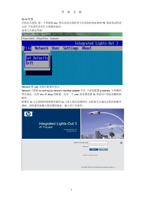
Hp ilo配置开机怎么进的第一个界面按any 然后还没出现阵列卡信息的时候赶紧按F8 我就是这样进去的不知道有没有什么便捷的途径。
进来之后就这界面,Network跟user是我们配置的重点,Network下面的nic and tcp/ip network interface adapter开启下面是配置ip address 子网掩码网关地址,还有dns和dhcp的配置。
还有一个user的设置设置ilo登录用户的添加删除权限等。
配置好ilo之后找跟网线将服务器的ilo口连入我们局域网内,这样就可以通过远程控制服务器啦,浏览器里面输入刚设置的地址,输入用户名密码。
远程控制啦本机电脑要按照相关软件的具体看说明,这个网页还有其他一些配置或者查看状态的基本上我用不到。
一切ok后点integrated remote console 以后就可以在自己电脑上全程控制服务器关机开机bios设置等等啦但是要注意有个问题就是你要买惠普的ilo的license不过可以注册一个免费使用60天的。
RBSU BIOS介绍篇开机画面看提示setup F9刚进来肯定是基本信息,设备类型,序列号,BIOS版本备份BIOS版本CPU内存按下tab 能看到网卡mac一、System optionsserial port options—virtual serial port 虚拟串口不可关闭哦,关闭了就不能用ILO远程管理控制二、Power management optionsHp power profile(惠普默认的电源或者功率配置)-balanced power and performance 平衡电源和性能模式minimum power usage 最小功率使用不知道能省多少电maximum performance最大功率和性能不知道能耗多少电Hp power regulator—hp dynamic power savings mode 动态电源模式(根据cpu工作量调整电源工作模式)hp static low power mode惠普静态低电压模式(系统保持低性能工作模式)Hp static high performance mode 惠普静态高性能模式(系统保持在高性能工作模式)Os control mode操作系统控制模式(在操作系统下开启电源管理策略)Redundant power supply mode(扩展的电压支持模式)---balanced mode平衡模式三、Pci IRQ settings pci中断设置四、PCI device enable/disable PCI设置(打开或关闭PCI设备)五、Standard boot order(IPL)设置启动顺序的硬盘启动光驱启动==六、Boot controller order 设置控制器的启动顺序,我进去就看到这列卡控制器跟intel sata controller#1好像是intel提高硬盘读写速度的什么技术,我做了阵列所以就选择阵列卡优先启动啦。
HP刀片服务器安装及配置
1.刀片與DL380,DL385的構建產線網絡的區別 2.刀片上的交換機配置 3.刀片上的交換機與服務器網卡的關係 4.刀片服務器的安裝方法
刀片與DL380,DL385的構建產線網絡的區 別
刀片服務器與380,385最大區別1,刀片上綁定了4個 cisco交換機.如圖:
這4個交換機與刀片服務器組合起來達到了380,385與負 載均衡3750組合的功能.這4個交換機相當于替代了 3750.2,刀片的web管理系統.給刀片設置web管理ip:
把pre rin 對應的端口劃到對應的vlan
第3台switch是swdl(192網段) 先劃vlan 在把對應 的端口劃到對應的vlan
第4台switch配置和第3台一樣 .
刀片上的交換機與服務器網卡的 關係
服務器上4塊網卡一一對應4台交換機.
前面介紹介紹過了:172的是第一台,10的第二 台,192的第三,第四台.當然,這是以前規劃好了 的.其實,只要了解交換機與服務器網卡之間的 關係,自己可以隨意發揮.
刀片也要掛載倒你的虛擬盤,我的虛擬光盤是G盤. 當windows copy完文件,準備安裝系統是會出現 如下介面:
大概就是告訴你系統找到擴展內存,存儲之內的 東西.在web介面ቤተ መጻሕፍቲ ባይዱ好系統 .
進入我的電腦,管理介面,看到沒,多了一塊磁盤,就 是剛剛擴展的東東.
點击右鍵,創建新的分區
一直下一步,出現如下畫面時,選擇F盤,快速格示 化
Ok到此系統就裝好了
刀片上的交換機配置
先給刀片後面的4台switch配上ip(ip按規劃的設) 進入web如圖所示
接下來需要用配置線在各個switch里設密碼,設遠 程登入(這我就不寫了) 第1台switch 是連sfc的172網段,默認到vlan1里 網線接好就ok.(要注意是3根線)1根連ilo,1根連 sfc的switch. 1根連10.252網段. 第2台switch是連10網段(image),兩條線pre,rin的 192網段. 10網段只有一個端口默認在vlan1里,這裡都在21 口.下面是兩條線pre,rin的192網段,先劃4個vlan.
HP服务器与存储系统安装、管理与故障排查指南说明书

This document is for the person who installs, administers, andtroubleshoots servers and storage systems. HP assumes that you are qualified in servicing computer equipment and trained in recognizing hazards in products with hazardous energy levels.© Copyright 2005 Hewlett-Packard Development Company, L.P .Hewlett-Packard Company makes no warranty of any kind with regard tothis material, including, but not limited to, the implied warranties of merchantability and fitness for a particular purpose. Hewlett-Packard shall not be liable for errors contained herein or for incidental or consequential damages in connection with the furnishing, performance, or use of this material.This document contains proprietary information, which is protected by copyright. No part of this document may be photocopied, reproduced, or translated into another language without the prior written consent of Hewlett-Packard. The information contained in this document is subject to change without notice.Hewlett-Packard Company shall not be liable for technical or editorial errors or omissions contained herein. The information is provided “as is” without warranty of any kind and is subject to change without notice. The warranties for Hewlett-Packard Company products are set forth in the express limited warranty statements accompa-nying such products. Nothing herein should be construed as constituting an additional warranty.Printed in the U.S.A.hp ProLiantDL585 Storage ServerHP ProLiant DL585 Storage Server Installation Instructions First Edition (March 2005)Part Number: 389150-001WARNING: This product contains energy levels that areconsidered hazardous. To reduce the risk of personal injury from electric shock and hazardous energy, individuals who are knowledgeable of the procedures, precautions, and hazards associated with equipment containing hazardous energy circuits must perform the installation and servicing of this product.•Obtain adequate assistance to lift and stabilize the chassis during installation or removal.•Be aware that the product becomes unstable when it is not fastened to the rails.•Before removing the server from the rack, remove all hot-plug power supplies, power modules, and drives to reduce the overall weight of the product.•Extend leveling jacks fully to the floor and make sure that the full weight of the rack rests on the leveling jacks.•Install stabilizing feet on single-rack installations.•Couple multiple-racks.•Only extend one rack component at a time. The rack will become unstable if more than one device is extended.A rack resource kit ships with all HP branded or Compaq branded 9000,10000, and H9 series racks. For more information on the content of each resource, refer to the rack resource kit documentation.If you intend to deploy and configure multiple servers in a single rack,refer to the white paper on high-density deployment at the HP website./products/servers/platformsThe HP ProLiant DL585 Storage Server is preloaded with the Windows ®Storage Server 2003 operating system. Prior to power up, deployment instructions found in the “User Guide” should be followed to enable the successful configuration of the storage server in addition to the guidelines found below.Required Items:User GuideAdministration GuideTo begin the first-time startup procedure:Be sure that the server is safely installed in an adequateenvironment.Be sure that the power cables and peripheral devices are plugged inand AC power is supplied to the server.Refer to the User Guide prior to powering up the server.389150-001Remove shipping bracket from the PCI Basket, loosen thethumbscrew (1) and remove and discard the shipping bracket (2).NOTE: The shipping bracket is used only to secure the PCIlatches during shipment.Install optionsIf you are installing additional options, such as expansion boards,processors, hard drives, or memory, refer to the instructionsincluded with the option.NOTE: For quick start memory guidelines, refer to the hood labels on theserver.1.Install the rails on both sides of the chassis.2.Pull the rail compression lever toward you.3.Install the rear of the rail into the designated holes in the rear ofthe rack.4.Install the front of the rail into the designated holes in the frontof the rack.5.Install the rails on the chassis into the rails in the rack.6.Slide the server onto the rack rails until the lockingpin engages.7.Tighten the thumbscrews to secure the server to the rack.The ProLiant DL585 server can operate either on a 120-V or a 240-V AC input. Two AC inlets are on the rear of the server, one for each power supply installed.WARNING: To reduce the risk of electric shock or damage to the equipment:•Do not disable the power cord-groundingplug. The grounding plug is an important safety feature.•Plug the power cord into a grounded (earthed)electrical outlet that is easily accessible at all times.•Disconnect power from the server by unpluggingthe power cord from either the electrical outlet or the server.To connect the power cord:1.Locate the correct voltage line cord that came with the server. Remove any labels that cover the cord connector.IMPORTANT: To connect the power cord, plug it into the appropriate power supply AC inlet. The power connector is connector number one for the primary (populated) power supply and is connector number two for the redundant hot-plug power supply.2.Plug the other end of the power cord into a grounded electrical outlet or UPS, depending on power cord type.3.Connect the peripheral device cables to the server, and then route the power cord and device cables through the cable management arm.Attaching cable management arm to a square-hole rack1.Slide the bracket onto the rack (1).2.Insert the bracket hooks into the square holes on the rack, and then push down to secure (2).3.Tighten the thumbscrew to stabilize the cable management armon the rack (3).Attaching the cable management arm to a round-hole rack1.Remove the square-hole bracket from the cable management arm by pulling out the spring-activated fasteners (1), and thenpulling out the bracket (2).2.Attach the round-hole bracket by pulling the spring-activated fasteners on the cable management arm out (1), and then inserting the bracket between them (2).3.Slide the bracket onto the rack (1).4.Attach the cable management arm to the round-hole rack, andthen secure the thumbscrews (2).To register your product visit the HP Registration web site at:Attaching the cable management arm to the server1.Loosen the thumbscrews on the front of the server to enable theserver to slide forward.3.Secure the cables to the inside of the cable management arm using the V elcro straps.2.Align the keyholes on the cable management arm with the postson the server (1), and then secure with the thumbscrew (2).Securing the cables to the cable management arm1.Align the pivot points of the cable management arm by slidingthe server as needed.2.Pivot the arm away from the server.4.Close the cable management arm and finish securing the cables.The hardware installation is now complete. Please refer to the “HP ProLiant Storage Server User Guide.”Installation Instructions Rack template tool used during rack installation contains:Administration guide User GuideHP Warranty fulfillment documentprovides instructions to obtain a printed warrantyHP Important Safety Information bookletSafety information for HP storage, power,networking and rack productsDocumentation CDrequirements and configuration options User Guiderack installation poster Administration Guideprovides administrative and procedural instructions to manage the storage server。
HP DL系列服务器RAID配置指南

HP ProLiant DL380、DL580、DL360服务器系列-配置Raid5的两种方法本文介绍DL380, DL580, DL360 服务器系列配置Raid 5的两种方法: 使用ORCA配置和使用Smart Start7.91中的Array Configuration Utility(ACU)配置。
方案一:使用ORCA配置Raid 51、开机自检到阵列卡时,有F8的提示。
2、F8进入阵列配置工具RBSU。
选择第一项:Create Logical Drive进入阵列创建界面。
3、用空格(space)键选中、Tab键切换选项。
将三块物理硬盘都选中;选择Raid 5;由于只用了三块sas硬盘,故不选spare;Maximum Boot partition:选择8GB maximum.按回车创建Raid 5。
4、F8保存配置。
5、示设置已保存,按回车键继续。
6、下面选View Loagical Driver,按回车查看阵列信息。
7、显示有一个logical drive,级别为Raid 5,状态OK。
8按回车查看详细信息。
显示阵列中物理盘的参数和状态以及是否有Spare盘。
方案二:使用Smart Start7.91中的Array Configuration Utility(ACU)配置Raid 5。
1、进入ACU(其中有两种方式可进入ACU):1.1用Smart Start7.91光盘引导进入Smart Start的主界面,选择Maintain Server-Configure Array。
1.2如果系统(以Windows系统为例)下已经安装了Proliant Support Pack(PSP包),则在开始-程序-HP System tools-HP Array Configuration Utility打开ACU。
2、创建Array。
在Configuration View选中Smart Array P400 in Slot3;在Comman Tasks选择Create Array。
HP服务器安装上架(精校版本)

HP服务器的安装上架2013年06月目录1接收CSAE单安装前以下问题进行确认 (3)1.1:咨询销售及负责人提供相关服务信息: (3)1.2:安装地点及环境条件: (3)1.3:确认实施时间 (3)1.4:送货前设备硬件检测 (3)1.5:技术配置要求以及相关文档 (3)2客户现场 (3)2.2:开箱检验 (4)2.3:机房确认机柜组成,机柜摆放及设备安装位置 (4)2.4:服务器上架及原则: (6)2.5:理线要求以及相关工具 (11)2.6:标签规格及作用: (12)2.7:上电,现场硬件检测(HP工具)有流程: (13)2.8:根据客户要求安装及配置 (17)2.9:清场验收。
(17)3.0:客户确认通知销售结单离开 (17)1接收CSAE单安装前以下问题进行确认1.1:咨询销售及负责人提供相关服务信息:1.1.1服务器的数量、型号以及选件(如:硬盘的大小和数量),服务器详细单。
1.1.2操作系统确认:安装配置要求。
1.2:安装地点及环境条件:1.2.1 机柜电流,温度、湿度及UPS品牌和供电电流。
1.2.2机柜所在机房确切位置,设备安装所在机柜位置。
1.3:确认实施时间1.4:送货前设备硬件检测1.5:技术配置要求以及相关文档2客户现场2.1:工作流程图客户现场清场验收确定操作系统开箱检验服务器上架Windows 操作系统安装Windows 操作系统配置Linux 操作系统安装Linux 操作系统配置硬件设备装机服务报告整改是否存在缺陷是否客户确认结束理线贴标签硬件检测2.2:开箱检验2.2.1:根据公司送货设备清单和邮件附注设备清单核对,一一点清验货注意相关配件。
2.3:机房确认机柜组成,机柜摆放及设备安装位置 2.3.1:机柜组成(19英寸标准机柜有24U ,42U 等类型)2.3.2:机柜准备2.3.2.1:调平机柜:机柜必须安放在一个稳固的地方,调节机柜底部的四个调节支脚,使机柜平稳的安放于地面。
- 1、下载文档前请自行甄别文档内容的完整性,平台不提供额外的编辑、内容补充、找答案等附加服务。
- 2、"仅部分预览"的文档,不可在线预览部分如存在完整性等问题,可反馈申请退款(可完整预览的文档不适用该条件!)。
- 3、如文档侵犯您的权益,请联系客服反馈,我们会尽快为您处理(人工客服工作时间:9:00-18:30)。
Create Array创建阵列
勾选Select All,选中系统检测出的磁盘,后点右下角<OK>
Create Logical Drive创建逻辑驱动器
单击右侧页面<Create Logical Drive>创建逻辑驱动器,或鼠 标右键点左侧树结构的驱动器创建。
Create Array创建阵列
操作系统安装配置(共六步)
第三步:选择Custom,设置操作系统安装的磁盘分区大小, 单位是M,其他项默认,单击右下角<Next>下一步
操作系统安装配置(共六步)
第四步:填写安装信息从上到下依次是计算机名称、管理员密码、 管理员密码确认量,填写完成后单击右下角<Next>下一步。
HP服务器安装说明
安装前准备
HP服务器随机器带的引导盘
操作系统安装光盘
引导盘说明
引导盘分为64位和32位两张,举例为64位操作系 统安装。(HP SmartStart)
服务器启动
按服务器电源开关,服务器启动,将HP SmartStart光盘放入 光驱。服务启动页面如下:
服务器启动
服务器会自动选择有光驱引导启动
第五步:此显示的是之前配置的安装信息,在确认无误后, 单击右下角<Next>进行安装,如有错误单击<Previous>返回 重新配置。
操作系统安装配置(共六步)
第六步:安装进度在27%后弹出HP SmartStart光盘,更换操 作系统安装光盘。
操作系统安装配置
第六步:安装进度在100%后弹出操作系统光盘,服务器自 动重启,进入蓝屏安装页面,复制文件。
Windows操作系统安装
单击<完成>,至此完成了操作系统的安装,进入系统,打 开设备管理器,查看设备状态。
通信未来 普天制造
操作系统安装配置(共六步)
第一步:选择操作系统安装的类型,HP-Branded Media是指 HP提供的媒体介质,Retail Media指的是普通零售媒体介质, 选择完成后直接单击右下角<Next>
操作系统安装配置(共六步)
第二步:这个页面是选择系统安装来源和操作系统格式, 默认即可,单击右下角<Next>下一步
Windows操作系统安装
复制文件完毕后,服务器自动重启进入安装页面,如果之 前配置的安装信息都正确(尤其是产品密钥),系统自动 安装,如果错误会弹出输入页面重新配置
Windows操作系统安装
Windows安装完成后自动重启,之后正常启动,输入操作系 统用户名密码后提示更换第二张操作系统安装光盘 (WindowsServer2003 R2是两张CD),更换好之后单击<确 定>安装提示安装即可。
(HP阵列配置和诊断)
选择设备
展开select an available device,选择列表中设备
现有阵列信息
下图所示是已经做过Raid的情况(RAID 1),这种情况 直接点左下角<Exit ACU>退出即可。
Create Array创建阵列
下图所示是没有做Raid的情况,单击右侧Create Array, 创建阵列。
选择RAID 1,后点右下角<Save>进行保存。
Create Array创建阵列
创建好磁盘阵列后,点击左下角<Exit ACU>退出。
返回
单击<Home>按钮返回。
Install操作系统安装
单击<Install>按钮进行操作系统的安装。
Install
操作系统安装配置(共六步)
第一步:选择操作系统安装的磁盘,如果只有一个Disk就 直接单击右下角<Next>
语言环境
选择语言环境,默认即可,因为没有简体中文。点<Next>
电子协议
阅读HP电子协议,点右下角Agree,进入下一页面
Select the operation to begin
单击Maintenance(维护)
HP阵列配置
单击HP Array Configuration and Diagnostics
操作系统安装配置(共六步)
第四步:此页面默认配置不需改动,单击右下角<Next>下 一步
操作系统安装配置(共六步)
第四步:网络配置,此页面默认配置不需改动,单击右下 角<Next>下一步
操作系统安装配置(共六步)
第四步:此页面默认配置不需改动,单击右下角<Next>下 一步
操作系统安装配置(共六步)