lpc210xx芯片资料
解读LPC210X之外部中断寄存器

解读LPC210X之外部中断寄存器LPC2101/02/03最多包含了三个外部中断输入作为可选择的管脚功能。
管脚进行组合后,外部事件可以处理成三个独立的中断信号。
外部中断输入能够可选择的用于将处理器从低功耗模式下唤醒。
此外,10个捕获输入没有可选择的将器件从低功耗模式唤醒功能,但也能够被用于外部中断。
Register descripTIon有四个寄存器涉及外部中断External Interrupt Flag register (EXTINT - 0xE01F C140)外部中断标志寄存器位信号描述复位值0EINT0对应管脚外部中断到来时,该标志位置位。
写1清除该位,如果该中断处于电平触发模式,那么电平触发期间该位不能清除。
01EINT1同EINT002EINT2同EINT007:3保留NA Interrupt Wake-up register (INTWAKE - 0xE01F C144)中断唤醒寄存器位信号描述复位值0EXTWAKE0置1时,指明EINT0中断将把处理器从低功耗模式唤醒01EXTWAKE1置1时,指明EINT1中断将把处理器从低功耗模式唤醒02EXTWAKE2置1时,指明EINT2中断将把处理器从低功耗模式唤醒014:3保留NA15RTCWAKE置1时,指明RTC中断将把处理器从低功耗模式唤醒External Interrupt Mode register (EXTMODE - 0xE01F C148)外部中断模式寄存器位信号描述复位值0EXTMODE00EINT0电平触发1EINT0边沿触发01EXTMODE10EINT1电平触发1EINT1边沿触发02EXTMODE20EINT2电平触发1EINT2边沿触发07:3保留NAExternal Interrupt Polarity register (EXTPOLAR - 0xE01F C14C)外部中断极性寄存器位信号描述复位值0EXTPOLAR00EINT0低电平或者上升沿触发1EINT0高电平后者下降沿触发01EXTPOLAR10EINT1低电平或者上升沿触发1EINT1高电平后者下降沿触发02EXTPOLAR20EINT2低电平或者上升沿触发1EINT2高电平后者下降沿触发07:3保留NA。
周立功NXPLPC21xx22xx系列ARM芯片的启动程序分解.
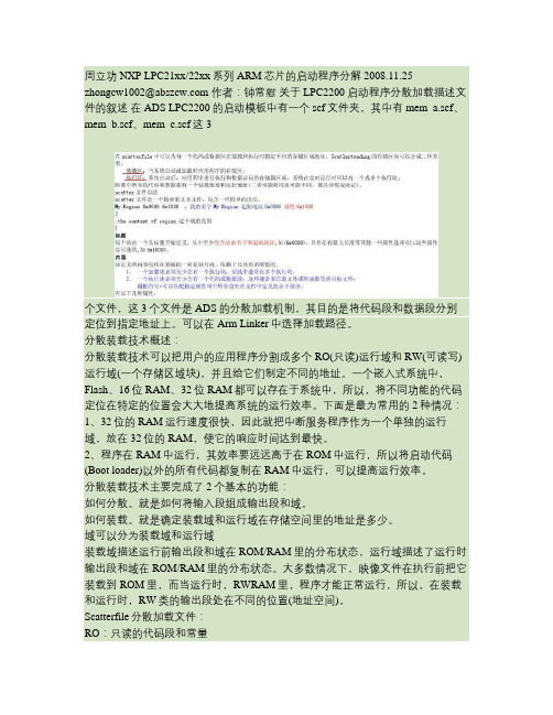
周立功NXP LPC21xx/22xx系列ARM芯片的启动程序分解 2008.11.25 zhongcw1002@ 作者:钟常慰关于LPC2200启动程序分散加载描述文件的叙述在ADS LPC2200的启动模板中有一个scf文件夹,其中有mem_a.scf、mem_b.scf、mem_c.scf这3个文件,这3个文件是ADS的分散加载机制,其目的是将代码段和数据段分别定位到指定地址上。
可以在Arm Linker中选择加载路径。
分散装载技术概述:分散装载技术可以把用户的应用程序分割成多个RO(只读)运行域和RW(可读写)运行域(一个存储区域块),并且给它们制定不同的地址。
一个嵌入式系统中,Flash、16位RAM、32位RAM都可以存在于系统中,所以,将不同功能的代码定位在特定的位置会大大地提高系统的运行效率。
下面是最为常用的2种情况:1、32位的RAM运行速度很快,因此就把中断服务程序作为一个单独的运行域,放在32位的RAM,使它的响应时间达到最快。
2、程序在RAM中运行,其效率要远远高于在ROM中运行,所以将启动代码(Boot loader)以外的所有代码都复制在RAM中运行,可以提高运行效率。
分散装载技术主要完成了2个基本的功能:如何分散。
就是如何将输入段组成输出段和域。
如何装载。
就是确定装载域和运行域在存储空间里的地址是多少。
域可以分为装载域和运行域装载域描述运行前输出段和域在ROM/RAM里的分布状态,运行域描述了运行时输出段和域在ROM/RAM里的分布状态。
大多数情况下,映像文件在执行前把它装载到ROM里,而当运行时,RWRAM里,程序才能正常运行,所以,在装载和运行时,RW类的输出段处在不同的位置(地址空间)。
Scatterfile分散加载文件:RO:只读的代码段和常量RW:可以读写的全局变量和静态变量ZI:RW段中要被初始化为零的变量。
Scatterfile中的定义要按照系统冲定向后的存储器分布情况进行,在引导程序完成初始化任务后,应该把主程序转移到RAM中运行以加快系统的运行速度。
七、串口的操作

与终端的连接
1、电路硬件方面,在Proteus ISIS里面添加一个终 、电路硬件方面, 里面添加一个终 引脚相连, 端terminal,并将该终端与芯片的 ,并将该终端与芯片的uart0引脚相连, 引脚相连 如范例电路图所示。 如范例电路图所示。 2、软件方面,程序的编译与前面的ADS环境配置一 、软件方面,程序的编译与前面的 环境配置一 程序需要首先确定晶振频率, 分频设定, 样,程序需要首先确定晶振频率,PLL分频设定,以 分频设定 及串口寄存器的设置。 及串口寄存器的设置。 波特率的设置很重要,一定不能有太大偏差, 波特率的设置很重要,一定不能有太大偏差,否则传 输数据错误。要双击芯片设置其晶振频率, 输数据错误。要双击芯片设置其晶振频率,或者修改 程序中的波特率设置数据,总之一定要一致。 程序中的波特率设置数据,总之一定要一致。
1、关于Proteus更进一步的学习请参考学习 、关于 更进一步的学习请参考学习 资料《 资料《Proteus 7 Professional 51单片机 入 单片机 门教程.pdf》 门教程 》 2、关于ADS更进一步的学习资料请参考课 、关于 更进一步的学习资料请参考课 本以及《 使用手册.pdf》 本以及《LPC213X&ADS1.2使用手册 使用手册 》 3、关于 、关于LPC213X系列芯片的功能以及使用 系列芯片的功能以及使用 寄存器等请参考手册《 寄存器等请参考手册《LPC213X芯片说明手 芯片说明手 册.pdf》 》
串口的配置
LPC21xx系列单片机一般包含 个串口,分别命名为 系列单片机一般包含1-2个串口 系列单片机一般包含 个串口, UART0和UART1,涉及到的寄存器很多,比如 和 ,涉及到的寄存器很多,比如UART0 的寄存器有: 的寄存器有:
J-Link使用说明
J-Link应用概述功能包括:●USB 2.0 interface●Any ARM7/ARM9/ARM11, Cortex-M3 core supported, including thumb mode ●Serial Wire Debug supported *●Serial Wire Viewer supported *●Automatic core recognition●Maximum JTAG speed 12 MHz●Download speed up to 720 Kbytes/second **●DCC speed up to 800 Kbytes/second **●Seamless integration into the IAR Embedded Workbench® IDE●No power supply required, powered through USB●SWV support since hardware version 6.0●Support for adaptive clocking●All JTAG signals can be monitored, target voltage can be measured●Support for multiple devices●Fully plug and play compatible●Standard 20-pin JTAG connector●Wide target voltage range: 1.2V - 3.3V, 5V tolerant●USB and 20-pin ribbon cable included●Memory viewer (J-Mem) included●TCP/IP server included, which allows using J-Link via TCP/IP networks●RDI interface available, which allows using J-Link with RDI compliant software ●Flash programming software (J-Flash) available●Flash DLL available, which allows using flash functionality in customapplications●Software Developer Kit (SDK) available●Embedded Trace Buffer (ETB) support●Adapter for 5V JTAG targets available●14-pin JTAG adapter available●Optical isolation adapter available●Target power supply: J-Link can supply up to 300 mA to target with overloadprotection●可以多个客户端同时访问一个目标板J-Link包括:●J-Flash ARM:Flash下载;●J-Link Commander:命令行;●J-Link GDB Server:GDB服务器;●J-Link RDI:RDI调试接口;●J-Link TCP-IP Server:TCP-IP远程调试接口;●J-Mem:内存察看器;J-Flash ARM可用于下载Flash1、通过File-New Project新建工程,也可通过File-Open Project打开一个已经配置好的工程。
05 第五讲 24C02读写实验--手把手教你学ARM之LPC2103入门篇-15页精选文档
属性 读/写
只读 读/写 读/写 读/写 读/写
复位值 0x00
0XF8 0x00 0x00 0x04 0x04
I2C0的地址 I2C1的地址和
和名称
名称
0xE001 C000
I2C0CONSE T
0xE005 C000 I2C1CONSET
0xE001 C004
I2C0STAT
0xE005 C004 I2C1STAT
手把手教你学ARM
——之LPC210x入门篇
主 讲: 何 呈 策 划:张 勇 学习板:LT-ARM210X
力天电子版权所有 LT430 2009年 1月
第五讲 24C02读写实验
要点:
IIC总线 LPC210X的IIC总线使用
主讲:何 呈
版权:力天电子
LT430
典型的IIC总线的连接框图
0xE001 C008
I2C0DAT
0xE005 C008 I2C1DAT
0xE001 CADR
0xE001
0xE005 C010
C010 I2C1SCLH
I2C0版SC权LH:力天电子
0xEL00T1430 0xE005 C014
IIC数据波特率的计算:
主讲:何 呈
版权:力天电子
LT430
LPC210X与24C02的硬件连接
主讲:何 呈
版权:力天电子
LT430
LPC210X读写24CO2程序编写
打开IAR开发环境 ……
主讲:何 呈
版权:力天电子
LT430
下一讲课程安排
第六讲、ARM定时器及外部中断程序设计
主讲:何 呈
版权:力天电子
主讲:何 呈
arm最小系统
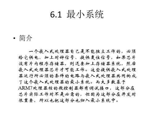
• 各部件简介 ——复位及其芯片配置
复位电路可以使用简单的阻容复位,这个电路成本 低廉,但不能保证任何情况产生稳定可靠的复位信号, 所以一般场合需要使用专门的复位芯片。
+3. 3 V
R1 1 0K
LPC2000
C1 4 7u
阻容复位
• 各部件简介 ——复位及其芯片配置
常用的复位专用芯片有CATALYST公司的CAT800系列,Sipex 公司的SP700系列和SP800系列。为了适应嵌入式系统的应用,这些 公司还推出带有EEPROM存储器和看门狗的复位芯片,这可以降低 系统成本和缩小产品体积,减少元件数量也有利于系统的稳定性。 如果系统不需要手动复位功能,可以选择CAT809。如果需要手 动复位功能,可以选择SP705/706、SP708SCN。
种类繁多的复位芯片可以满足不同工作电压和不同复位方式的 系统,这里仅介绍其中部分。
注意:复位芯片的复位门槛的选择至关重要,一般应当选择微控制 器的IO口供电电压范围为标准。LPC2000这个范围为:3.0V~3.6V, 所以选择复位门槛电压为2.93V,即电源电压低于2.93V时产生复位 信号。
• 各部件简介 ——复位及其芯片配置
• 各部件简介 ——电源
CZ1
POWER(9V)
C4 1 04
C1 2 20 uF/35 V
GND
1 2 3
D1 1 N58 19
U1 1 SPX1 11 7M 3-1 . 8 1 Vin Vo ut 3 +5V
C2 1 04
C3 2 20 uF/35 V
模拟电源
CZ1
1 2 3
D1 1 N58 19
嵌入式控制器
复位及其 配置系统
Silicon Labs CP210X虚拟COM端口驱动器与Android平台集成指南说明书
AN809: Integrating the CP210X Virtual COM Port Driver into the Android Platform This document describes how to build an Android kernel and the steps needed to inte-grate the CP210x virtual COM port (VCP) driver in to the build.Android is based off of the Linux kernel, so there is already support for the CP210x de-vice built in to the kernel. However, CP210x support is not included in a default kernel build configuration for most Android devices.There are many devices that can run the Android operating system (OS), as well as several different versions of an Android operating system. Because Android is open source, it can be changed based on the needs of device manufacturers, wireless carri-ers and other developers. This fact makes it difficult to provide the exact steps for re-building, as each developer may be using different hardware and a different build of Android specific to that hardware.This document was written based on the experience of building an Android Jelly Bean (4.3.1) kernel for a PandaBoard using a TI OMAP4430 processor. The Android port used originates from the 13.10 release from Linaro. Build materials and information on this specific release can be found at /archive/13.10/android/ images/panda-linaro/. If you are using another platform, you should consult the manu-facturer's website to get the Android distribution support for your device. Although the steps below are targeted to Jelly Bean on the PandaBoard, developers can follow simi-lar steps to download and rebuild the kernel for other platforms. For any other needs specific to Android, visit the Android Developer website at.KEY POINTS•Steps for integrating the CP210x VCP driver into an Android kernel.•Testing the CP210x VCP driver in Android.1. MaterialsTo build a custom Android kernel and image, you will need:•CP210x USB to UART Bridge Evaluation Board•Target Android Device (PandaBoard)•SD card to hold OS•Any cables for connectivity (HDMI video cable, network cable, USB power cable, USB to RS232 adapter)•Source Distribution for Target Android Version (Linaro 13.10 - JellyBean 4.3.1 Android Release for PandaBoard)•Toolchain to build the Source Distribution (Android NDK, Revision 9C)•Development System Running Linux (Ubuntu 12.04 LTS)2. OverviewThe basic steps to integrate support for the CP210x driver are:•Create bootable image on an SD Card from the Android source distribution •Download the Android build tools for the target Android source and platform •Download the Android source tree for the target platform•Modify the configuration of the kernel to include the CP210x and other required drivers •Build and install the new image to the target platform mediaCreate Bootable Image on an SD Card 3. Create Bootable Image on an SD CardTo replace the kernel on a device’s media, you will need to create a bootable device. Typically, a source distribution will contain prebuilt binaries that can be loaded directly on to an SD Card. Loading a complete prebuilt image enables you to make sure that the version works on your platform and allows you to replace only the kernel instead of rebuilding the entire Android distribution from scratch. Linaro provides these prebuilt binaries for its supported devices. The following instructions describe how to use your development sys-tem to download the prebuilt images to a PandaBoard device and test that the PandaBoard can boot and run Android without any is-sues.e Android 4.3.1 (Jelly Bean) for the PandaBoard from Linaro’s 13.10 release version. The specific version can be found underthe Linaro Engineering Builds on /archive/13.10/android/images/panda-linaro/. Download the following files to the development system to a known and accessible location, such as your home directory:•boot.tar.bz2•system.tar.bz2•userdata.tar.bz22.Next, on the development system, install and update for the Linaro Image Tools:$ sudo add-apt-repository ppa:linaro-maintainers/tools$ sudo apt-get update$ sudo apt-get install linaro-image-tools3.Disable the automount so you can properly image your SD card:$ dconf write /org/gnome/desktop/media-handling/automount false$ dconf write /org/gnome/desktop/media-handling/automount-open false4.To image your SD card, first find out what the device name is. Start by inserting your SD card and running:$ dmesg5.You should see something similar to the following at the end of your log:sdb: sdb1 sdb2 sdb3 sdb4 < sdb5 sdb6 >6.Navigate to the directory where the boot/system/userdata.tar.bz2 files were downloaded. Ensure that the device above is indeedassociated with your SD card (otherwise you can erase your hard drive) and create the media using the Linaro imaging tools: $ linaro-android-media-create --mmc /dev/sdc --dev panda --boot boot.tar.bz2–-system system.tar.bz2 --userdata userdata.tar.bz27.Next, install the graphics libraries to the device (do this immediately after creating the media, before removing the SD card):$ wget /~vishalbhoj/install-binaries-4.0.4.sh$ chmod a+x install-binaries-4.0.4.sh$ ./install-binaries-4.0.4.sh8.Finally, restore the automount:$ dconf write /org/gnome/desktop/media-handling/automount true$ dconf write /org/gnome/desktop/media-handling/automount-open true9.The SD card is now ready to boot. Insert it into the SD card slot on the PandaBoard and hook up a monitor to the HDMI output anda keyboard and mouse to the USB ports. Connect the RS232 connection up to your development system. This is the Android de-bug port, and will output logging information from the PandaBoard at a baud rate of 115200, 8N1. This also serves as a root termi-nal in to the device. Once everything is connected, power the board to start the boot sequence. If this works, then you can move on to the next steps of replacing the kernel image on this device.To build the source from an Android distribution, you will need the toolchain that can build the source for your platform. This can be different between devices, so check with the manufacturer to find out what toolchain to use for your device.1.For Android Jelly Bean (4.3.1) on the PandaBoard, use the arm-linux-androideabi 4.6 version from the Android NDK, Revision 9C.This can be downloaded directly from the Android Developer website at: /tools/sdk/ndk/index.html.Here is a link to the specific version:Android NDK, Revision 9C: /android/ndk/android-ndk-r9c-linux-x86_64.tar.bz2After downloading these tools, extract them into a known and accessible location, such as your home directory.2.Next, you will need to set the PATH variable to include the specific path to the correct version of the prebuilt toolchain. In this ex-ample, we have extracted the Android NDK to the home directory and used the following path to target the 4.6 version of the tools (replace <username> with your username):$ export PATH=$PATH:/home/<username>/android-ndk-r9c/toolchains/arm-linux-androideabi-4.6/prebuilt/linux-x86_64/bin3.Additionally, a few other tools will need to be installed on your development system. Use the following commands to install them:$ sudo apt-get install git$ sudo apt-get install curl$ sudo apt-get install ncurses-dev$ sudo apt-get install uboot-mkimageNext, you will need to download the Android source. The manufacturer for your device should have its own repository for the download, or should be able to point to a specific revision to download.In this example, you will clone the Linaro PandaBoard source and checkout a version specific to the 13.10 build. This will allow you to rebuild the kernel and replace it on the media that was also created from 13.10.Note: The following steps were taken from Linaro’s build script “linaro_kernel_build_cmds.sh”, and is how to obtain the version to check out and links to rebuild. For reference, this file can be found at /archive/13.10/android/images/panda-linaro/ linaro_kernel_build_cmds.sh.1.Download the source for your development board:$ git clone git:///kernel/panda2.Navigate to the source directory and checkout the source tree for version 13.10:$ cd linaro-kernel$ git checkout ca4b45c8f598951b828ca968f5953b8d5e85e34c6. Modify the Configuration of the KernelOnce the Android kernel source has been downloaded, you will need to create a configuration for the kernel. Linaro already has a de-fault configuration so it is easiest to start with this and add in your CP210x support. The following steps describe how to do this.1.Download the kernel configuration from Linaro to a “.config” file to be used by the build:$ curl -q /android/~linaro-android-member-ti/panda-linaro-13.10-release/3/ kernel_config > .confige the menuconfig to update the configuration for CP210x support:$ make ARCH=arm menuconfigIn the menuconfig UI, navigate to the Device Drivers section:Figure 6.1. menuconfig: Device DriversThen navigate to the USB Support section (this should already be marked with a *).Figure 6.2. menuconfig: USB SupportThen navigate to the USB Serial Converter Support section. Press the space bar until this item shows up as a *, then enter the section to edit the USB converter support:Figure 6.3. menuconfig: USB Serial Converter SupportHighlight USB Generic Serial Driver and press the space bar until this item shows up as a *. Then navigate down to the USB CP210x family of UART Bridge Controllers and press the space bar until this item shows up as a *. Finally, exit it out of each section:Figure 6.4. menuconfig: USB Serial Converter FeaturesOn the final page, select Yes to save the configuration in to the “.config” file:Figure 6.5. menuconfig: Save ConfigurationAt this point everything is setup to build the CP210x in to the kernel.Note: The Android Jelly Bean (4.3.1) OS is based on a 2.6 version of the Linux kernel. Basic support for CP2101/2/3 devices are inclu-ded in the kernel by default, but the driver is not up to date for newer devices such as CP2104/5/8/9. To get support for these, you will need to replace the cp210x.c driver file in the source before you build your kernel image. Perform the following steps to replace the file: 1.Download the Linux 2.6 driver from the Silicon Labs website:/Support%20Documents/Software/Linux_2.6.x_VCP_Driver_Source.zip2.Extract the cp210x.c file in to the kernel source tree. The original cp210x.c file is located in the tree under <base kernel directory>/drivers/usb/serial.3.Rebuild the kernel using the steps below.Build and Install the New Image 7. Build and Install the New ImageOnce you confirm your device works and boots off of the known media, you have downloaded the necessary toolchain and the Android kernel source tree can build your kernel image.1.To build the source run the following command:$ make ARCH=arm CROSS_COMPILE=arm-linux=andorideabi- uImage2.When your build completes successfully, you can find your ‘uImage’ file under <base kernel directory>/arch/arm/boot.3.The final step is to replace the “uImage” file on the boot device with the new one. Reinsert the original SD card that contains theprebuilt bootable image. You should see multiple partitions come up on this device. Navigate to the “boot” partition and delete the “uImage” file on the device, then copy over the new one from your build.4.The SD card is now ready to boot. Insert it into the SD card slot on the PandaBoard, hook up a monitor to the HDMI output and akeyboard and mouse to the USB ports. Connect the RS232 connection up to your development system using minicom or some other terminal program (115200, 8N1).Testing the CP210x Driver in Android 8. Testing the CP210x Driver in AndroidWhen your PandaBoard boots up, you can plug in a CP210x device to the USB host port on the PandaBoard. On the host terminal connected to the Android debug port you should see something similar to the following output:[ 104.627380] usb 1-1.3: new full-speed USB device number 8 using ehci-omap[ 104.764923] usb 1-1.3: New USB device found, idVendor=10c4, idProduct=ea60[ 104.772338] usb 1-1.3: New USB device strings: Mfr=1, Product=2, SerialNumber=3[ 104.786437] usb 1-1.3: Product: CP2104 USB to UART Bridge Controller[ 104.803405] usb 1-1.3: Manufacturer: Silicon Labs[ 104.810241] usb 1-1.3: SerialNumber: 0001[ 104.836822] cp210x 1-1.3:1.0: cp210x converter detected[ 104.845794] usb 1-1.3: cp210x converter now attached to ttyUSB0The last line will specify what tty device the CP210x will be accessible through, in this case it is “ttyUSB0”.To do a quick test to see that data is going through the device type the following commands in the Android debug port terminal:$ stty –F /dev/ttyUSB0 115200$ stty –F /dev/ttyUSB0 –aspeed 115200 baud;stty: /dev/ttyUSB0line = 0;intr = ^C; quit = ^\; erase = ^?; kill = ^U; eof = ^D; eol = <undef>;eol2 = <undef>; swtch = <undef>; start = ^Q; stop = ^S; susp = ^Z; rprnt = ^R;werase = ^W; lnext = ^V; flush = ^O; min = 1; time = 0;-parenb -parodd cs8 hupcl -cstopb cread clocal -crtscts-ignbrk -brkint -ignpar -parmrk -inpck -istrip -inlcr -igncr icrnl ixon -ixoff-iuclc -ixany -imaxbel -iutf8opost -olcuc -ocrnl onlcr -onocr -onlret -ofill -ofdel nl0 cr0 tab0 bs0 vt0 ff0isig icanon iexten echo echoe echok -echonl -noflsh -xcase -tostop -echoprtechoctl echokeThe first command will set the baud rate, then the second command will show the baud rate has been set (underlined and in green above). Hook your CP210x device up to another terminal set to that baud rate, 115200. Then we can see that data goes across by typing the following command in to our Android debug port terminal:$ ls /dev > /dev/ttyUSB0This should display the directory listing for /dev on your Android device in the other terminal and confirm that it is transmitting data across the CP210x as expected.Note: Some CP210x devices flush buffers on close, so the directory listing might not be complete since the open, data transmission, and close happen quicker than data can exit the device. Certain devices can be configured to avoid this behavior by using the steps outlined in application note, “AN721: CP21xx Device Customization Guide.” Under normal operation where an application is developed, the port should be kept open for the duration of the time needed for transmission or configured to not flush buffers on closed if suppor-ted and desired.Conclusion 9. ConclusionThis application note explained how to build the CP210x VCP driver into an Android kernel. Upon completion of these steps, a develop-er can then utilize the CP210x device as a data transmission or data acquisition device for Android. The device can be used in applica-tions developed for the Android platform as services or end user applications developed with the Android SDK.Revision History 10. Revision HistoryRevision 0.2May 2023•Updated Linaro links.•Converted document to new format.Revision 0.1September 2016•Initial versionSilicon Laboratories Inc.400 West Cesar Chavez Austin, TX 78701USA IoT Portfolio /IoT SW/HW /simplicity Quality /quality Support & Community /communityDisclaimerSilicon Labs intends to provide customers with the latest, accurate, and in-depth documentation of all peripherals and modules available for system and software imple-menters using or intending to use the Silicon Labs products. Characterization data, available modules and peripherals, memory sizes and memory addresses refer to each specific device, and “Typical” parameters provided can and do vary in different applications. Application examples described herein are for illustrative purposes only. Silicon Labs reserves the right to make changes without further notice to the product information, specifications, and descriptions herein, and does not give warranties as to the accuracy or completeness of the included information. Without prior notification, Silicon Labs may update product firmware during the manufacturing process for security or reliability reasons. Such changes will not alter the specifications or the performance of the product. Silicon Labs shall have no liability for the consequences of use of the infor -mation supplied in this document. This document does not imply or expressly grant any license to design or fabricate any integrated circuits. The products are not designed or authorized to be used within any FDA Class III devices, applications for which FDA premarket approval is required or Life Support Systems without the specific written consent of Silicon Labs. A “Life Support System” is any product or system intended to support or sustain life and/or health, which, if it fails, can be reasonably expected to result in significant personal injury or death. Silicon Labs products are not designed or authorized for military applications. Silicon Labs products shall under no circumstances be used in weapons of mass destruction including (but not limited to) nuclear, biological or chemical weapons, or missiles capable of delivering such weapons. Silicon Labs disclaims all express and implied warranties and shall not be responsible or liable for any injuries or damages related to use of a Silicon Labs product in such unauthorized applications. Note: This content may contain offensive terminology that is now obsolete. Silicon Labs is replacing these terms with inclusive language wherever possible. For more information, visit /about-us/inclusive-lexicon-projectTrademark InformationSilicon Laboratories Inc.®, Silicon Laboratories ®, Silicon Labs ®, SiLabs ® and the Silicon Labs logo ®, Bluegiga ®, Bluegiga Logo ®, EFM ®, EFM32®, EFR, Ember ®, Energy Micro, Energy Micro logo and combinations thereof, “the world’s most energy friendly microcontrollers”, Redpine Signals ®, WiSeConnect , n-Link, ThreadArch ®, EZLink ®, EZRadio ®, EZRadioPRO ®, Gecko ®, Gecko OS, Gecko OS Studio, Precision32®, Simplicity Studio ®, Telegesis, the Telegesis Logo ®, USBXpress ® , Zentri, the Zentri logo and Zentri DMS, Z-Wave ®, and others are trademarks or registered trademarks of Silicon Labs. ARM, CORTEX, Cortex-M3 and THUMB are trademarks or registered trademarks of ARM Holdings. Keil is a registered trademark of ARM Limited. Wi-Fi is a registered trademark of the Wi-Fi Alliance. All other products or brand names mentioned herein are trademarks of their respective holders.。
03 第三讲 LPC210X的PLL设置及GPIO操作--手把手教你学ARM之LPC2103入门篇
MSEL
PLL倍频序数。
0
6:5
PSEL
PLL分频序数。
无效
0
7
-
NA
主讲:何
呈
版权:力天电子
PLL状态寄存器 PLLSTAT
位 4:0 6:5 7 8 9 符号 MSEL PSEL PLLE PLLC 描述 PLL倍频序数的回读值。这是PLL当前使用的数值。 PLL分频序数的回读值。这是PLL当前是用的数值。 无效 PLL使能状态的回读值。但为1的时候,代表PLL有效,为0 表示PLL关闭。当系统进入掉电模式时,此位自动清0。 PLL连接状态的回读值。但PLLE和PLLC都为1,PLL的输 出作为微控制的时钟源;当它们中有任意一个为0时,不会 使用PLL,而直接使用晶体振荡器的频率。 反映PLL的锁定状态,当为0时,表示PLL没有锁住;当为1 时,表示PLL锁定在要求的频率。 无效 复位值 0 0 NA 0 0
10 15:11
PLOCK -
0 NA
主讲:何
呈
版权:力天电子
PLL操作寄存器器 PLLFEED
要使PLLCON和PLLCFG中的值有效,必须按次序 且连续地向PLLFEED寄存器写入0xAA,0x55;否 则,PLLCON和PLLCFG中设定的参数将不会有效。 复位值0x00;
手把手教你学ARM
——之LPC210x入门篇
主 策
讲: 何 划:张
呈 勇
力天电子版权所有 2009年 1月
学习板:LT-ARM210X
LPC210X的PLL设置 及GPIO操作(P24)
主讲:何
呈
版权:力天电子
LPC210X的PLL设置 及GPIO操作
Silicon Laboratories CP210x GPIO 控制指南说明书
Rev. 0.5 3/13Copyright © 2013 by Silicon LaboratoriesAN2231. IntroductionSome CP210x devices include GPIO pins that can be controlled by the PC using a Dynamic Link Library (DLL).The default configuration of these pins is controlled by the software included in AN721, “CP210x/CP211x DeviceCustomization Guide,” available on the interface application note web page (/products/Interface/Pages/interface-application-notes.aspx ). This document discusses reading and writing the state of thesepins with software.The CP210x Port Read/Write Example illustrates how the GPIO latch can be read from and written to using theCP210xRuntime.DLL . The functions in this API (CP210xRT_ReadLatch() and CP210xRT_WriteLatch()) give host-based software access to the CP210x device’s GPIO latch using the USB connection as shown in Figure 1.Figure 1.Main WindowThe main window of the CP210x Port Read/Write Example contains one section to write the GPIO latch andanother to read the GPIO latch. Below that is a list to select a COM port and display boxes for the device partnumber, product string, and serial number.To write new values to the latch, select which GPIO pins to update, and set the pin state for each. Any GPIO pinsnot selected to change will remain static when the “Write Latch” button is pressed. The “Write Latch” button callsthe CP210xRT_WriteLatch() function followed by the CP210xRT_ReadLatch() function, which updates the valuesdisplayed in the Read Latch portion of the dialog. At any time, the “Read Latch” button can be pressed to read inthe current GPIO pin state of the device.AN2232. Creating Custom Applications using CP210xRuntime.DLLCustom applications can use the CP210x Runtime API implemented in CP210xRuntime.DLL. To use functions implemented in CP210xRuntime.DLL, link CP210xRuntime.LIB with your Visual C++ 6.0 application. Include CP210xRuntimeDLL.h in any file that calls functions implemented in CP210xRuntime.DLL.3. CP210x Runtime API FunctionsThe CP210x Runtime API provides access to the GPIO port latch, and is meant for distribution with the product containing a CP210x device.⏹ CP210xRT_ReadLatch()—Returns the GPIO port latch of a CP210x device.⏹ CP210xRT_WriteLatch()—Sets the GPIO port latch of a CP210x device.⏹ CP210xRT_GetPartNumber()—Returns the 1-byte Part Number of a CP210x device.⏹ CP210xRT_GetProductString ()—Returns the product string programmed to the device.⏹ CP210xRT_GetDeviceSerialNumber ()—Returns the serial number programmed to the device.⏹ CP210xRT_GetDeviceInterfaceString ()—Returns the interface string programmed to the device. Typically, the user initiates communication with the target CP210x device by opening a handle to a COM port using CreateFile() (See AN197: “Serial Communication Guide for CP210x”). The handle returned allows the user to call the API functions listed above. Each of these functions is described in the following sections. Type definitions and constants are defined in the file CP210xRuntimeDLL.h.Note:Functions calls into this API are blocked until completed. This can take several milliseconds depending on USB traffic.3.1. CP210xRT_ReadLatchDescription:Gets the current port latch value from the device.Supported Devices:CP2103, CP2104, CP2105, CP2108Location:CP210x Runtime DLLPrototype:CP210x_STATUS CP210xRT_ReadLatch(HANDLE Handle, LPWORD Latch)Parameters: 1.Handle—Handle to the Com port returned by CreateFile().tch—Pointer for 4-byte return GPIO latch value [Logic High=1, Logic Low=0].Return Value:CP210x_STATUS=CP210x_SUCCESS,CP210x_INVALID_HANDLE,CP210x_DEVICE_IO_FAILEDCP210x_FUNCTION_NOT_SUPPORTEDAN223 3.2. CP210xRT_WriteLatchDescription:Sets the current port latch value for the device.Supported Devices:CP2103, CP2104, CP2105, CP2108Location:CP210x Runtime DLLPrototype:CP210x_STATUS CP210xRT_WriteLatch(HANDLE Handle, WORD Mask, WORD Latch)Parameters: 1.Handle—Handle to the Com port returned by CreateFile().2.Mask—Determines which pins to change [Change = 1, Leave = 0].tch—4-byte value to write to GPIO latch [Logic High = 1, Logic Low = 0]Return Value:CP210x_STATUS=CP210x_SUCCESS,CP210x_INVALID_HANDLE,CP210x_DEVICE_IO_FAILEDCP210x_FUNCTION_NOT_SUPPORTED3.3. CP210xRT_GetPartNumberDescription:Gets the part number of the current device.Supported Devices:CP2101, CP2102, CP2103, CP2104, CP2105, CP2108Location:CP210x Runtime DLLPrototype:CP210x_STATUS CP210xRT_GetPartNumber(HANDLE Handle, LPBYTE PartNum)Parameters: 1.Handle—Handle to the Com port returned by CreateFile().2.PartNum—Pointer to a byte containing the return code for the part number.Return Value:CP210x_STATUS=CP210x_SUCCESS,CP210x_INVALID_HANDLE,CP210x_DEVICE_IO_FAILEDAN2233.4. CP210xRT_GetDeviceProductStringDescription:Gets the product string in the current device.Supported Devices:CP2101, CP2102, CP2103, CP2104, CP2105, CP2108Location:CP210x Runtime DLLPrototype:CP210x_STATUS CP210xRT_GetDeviceProductString(HANDLE cyHandle, LPVOID lpProduct, LPBYTE lpbLength, BOOL bConvertToASCII = TRUE) Parameters: 1.Handle—Handle to the Com port returned by CreateFile().2.lpProduct—Variable of type CP210x_PRODUCT_STRING returning the NULL terminatedproduct string.3.lpbLength—Length in characters (not bytes) not including a NULL terminator.4.ConvertToASCII—Boolean that determines whether the string should be left in Unicode, orconverted to ASCII. This parameter is true by default, and will convert to ASCII.Return Value:CP210x_STATUS=CP210x_SUCCESS,CP210x_INVALID_HANDLE,CP210x_DEVICE_IO_FAILEDCP210x_INVALID_PARAMETER3.5. CP210xRT_GetDeviceSerialNumberDescription:Gets the serial number in the current device.Supported Devices:CP2101, CP2102, CP2103, CP2104, CP2105, CP2108Location:CP210x Runtime DLLPrototype:CP210x_STATUS CP210xRT_GetDeviceSerialNumber(HANDLE cyHandle,LPVOID lpProduct, LPBYTE lpbLength, BOOL bConvertToASCII = TRUE)Parameters: 1.Handle—Handle to the Com port returned by CreateFile().2.lpProduct—Variable of type CP210x_SERIAL_STRING returning the NULL terminated serialstring.3.lpbLength—Length in characters (not bytes) not including a NULL terminator.4.ConvertToASCII—Boolean that determines whether the string should be left in Unicode, orconverted to ASCII. This parameter is true by default, and will convert to ASCII.Return Value:CP210x_STATUS=CP210x_SUCCESS,CP210x_INVALID_HANDLE,CP210x_DEVICE_IO_FAILEDCP210x_INVALID_PARAMETERAN223 3.6. CP210xRT_GetDeviceInterfaceStringDescription:Gets the interface string of the current device.Supported Devices:CP2105, CP2108Location:CP210x Runtime DLLPrototype:CP210x_STATUS CP210xRT_GetDeviceInterfaceString(HANDLE cyHandle, LPVOID lpInterfaceString, LPBYTE lpbLength, BOOL bConvertToASCII = TRUE) Parameters: 1.Handle—Handle to the Com port returned by CreateFile().2.lpInterfaceString—Variable of type CP210x_SERIAL_STRING returning the NULL terminatedinterface string.3.lpbLength—Length in characters (not bytes) not including a NULL terminator.4.ConvertToASCII—Boolean that determines whether the string should be left in Unicode, orconverted to ASCII. This parameter is true by default, and will convert to ASCII.Return Value:CP210x_STATUS=CP210x_SUCCESS,CP210x_INVALID_HANDLE,CP210x_DEVICE_IO_FAILEDCP210x_INVALID_PARAMETERAN223D OCUMENT C HANGE L ISTRevision 0.1 to Revision 0.2⏹Reworded Open Drain Output description for clarityRevision 0.2 to Revision 0.3⏹Added CP210xRT_GetProductString⏹Added CP210xRT_GetDeviceSerialNumber⏹Added CP210xRT_GetDeviceProductString Revision 0.3 to Revision 0.4⏹Added support for CP2104 and CP2105⏹Added CP210xRT_GetDeviceInterfaceString ⏹Added Table 3 and Table 4⏹Added Section 5.6. CP2105 GPIO Mode and Modem Mode ⏹Removed the AppendixRevision 0.4 to Revision 0.5⏹Removed sections regarding port configuration.⏹Updated interfaces to ReadLatch and WriteLatchfrom BYTE/LPBYTE to WORD/LPWORD.⏹Added CP2108 as a supported device to allfunctions. Silicon Laboratories Inc.400 West Cesar ChavezAustin, TX 78701USASimplicity StudioOne-click access to MCU andwireless tools, documentation,software, source code libraries &more. Available for Windows,Mac and Linux!IoT Portfolio/IoT SW/HW /simplicity Quality /quality Support and CommunityDisclaimerSilicon Labs intends to provide customers with the latest, accurate, and in-depth documentation of all peripherals and modules available for system and software implementers using or intending to use the Silicon Labs products. Characterization data, available modules and peripherals, memory sizes and memory addresses refer to each specific device, and "Typical" parameters provided can and do vary in different applications. Application examples described herein are for illustrative purposes only. Silicon Labs reserves the right to make changes without further notice and limitation to product information, specifications, and descriptions herein, and does not give warranties as to the accuracy or completeness of the included information. Silicon Labs shall have no liability for the consequences of use of the information supplied herein. This document does not imply or express copyright licenses granted hereunder to design or fabricate any integrated circuits. The products are not designed or authorized to be used within any Life Support System without the specific written consent of Silicon Labs. A "Life Support System" is any product or system intended to support or sustain life and/or health, which, if it fails, can be reasonably expected to result in significant personal injury or death. Silicon Labs products are not designed or authorized for military applications. Silicon Labs products shall under no circumstances be used in weapons of mass destruction including (but not limited to) nuclear, biological or chemical weapons, or missiles capable of delivering such weapons.Trademark InformationSilicon Laboratories Inc.® , Silicon Laboratories®, Silicon Labs®, SiLabs® and the Silicon Labs logo®, Bluegiga®, Bluegiga Logo®, Clockbuilder®, CMEMS®, DSPLL®, EFM®, EFM32®, EFR, Ember®, Energy Micro, Energy Micro logo and combinations thereof, "the world’s most energy friendly microcontrollers", Ember®, EZLink®, EZRadio®, EZRadioPRO®, Gecko®, ISOmodem®, Precision32®, ProSLIC®, Simplicity Studio®, SiPHY®, Telegesis, the Telegesis Logo®, USBXpress® and others are trademarks or registered trademarks of Silicon Labs. ARM, CORTEX, Cortex-M3 and THUMB are trademarks or registered trademarks of ARM Holdings. Keil is a registered trademark of ARM Limited. All other products or brand names mentioned herein are trademarks of their respective holders.。
CP210x_CP211x_OverviewTechnical
• • •
HID
USB HID API to simplify host application development Allows implementation of USB applications without USB expertise Royalty-free, customizable Windows certified device driver
Host application software remains unchanged since it still accesses a standard com port Uses custom virtual com port driver (provided by Silicon Labs) to pass data from the com port to the USB low level stack
Performs bridging between USB and another communications interfaces such as UART or SMBus\I2C HID is a defined USB class that operating systems support natively
CP21xx
CP21xx Features
HID-USB support (CP2110 and CP2112)
Hale Waihona Puke Customer Benefit
• No driver installation required • Seamless compatibility with most operating systems • Reduces BOM cost by eliminating • Quartz crystal • External memories • Reduces PCB space • Shortens time to market • Reduces software development expertise requirements
- 1、下载文档前请自行甄别文档内容的完整性,平台不提供额外的编辑、内容补充、找答案等附加服务。
- 2、"仅部分预览"的文档,不可在线预览部分如存在完整性等问题,可反馈申请退款(可完整预览的文档不适用该条件!)。
- 3、如文档侵犯您的权益,请联系客服反馈,我们会尽快为您处理(人工客服工作时间:9:00-18:30)。
类型
描述
P0.13 P0 口位 13
O DTR1 UART1 的数据终端就绪输出
O MAT1.1 定时器 1 匹配输出 1
P0.14 P0 口位 14
I DCD1 UART1 数据载波检测输入
I EINT1 外部中断 1 输入
P0.15 P0 口位 15
I RI1
UART1 铃声指示输入
I EINT2 外部中断 2 输入
管脚描述 管脚名称 P0.0~P0.31
LQFP
13
14
18
21
22
23
24
28
29
30
35
36
37
类型
描述
I/O P0 口 P0 口是一个 32 位双向 I/O 口 每个位都有独立的方向控制 P0
口管脚的操作取决于管脚连接模块所选择的功能
P0.0 P0 口位 0
O TxD0 UART0 的发送器输出
O MAT0.0 定时器 0 匹配输出 0
P0.4
P0 口位 4
I/O SCK 串行时钟 SPI 主机输出或从机输入的时钟
I CAP0.1 定时器 0 捕获输入 1
P0.5
P0 口位 5
I/O MISO 主机输入从机输出 SPI 从机到主机的数据传输
O MAT0.1 定时器 0 匹配输出 1
P0.6
O PWM1 脉宽调制器输出 1
P0.1 P0 口位 1
I RxD0 UART0 的接收器输入
O PWM3 脉宽调制器输出 3
P0.2 P0 口位 2
I/O SCL I2C 时钟输入/输出 开漏输出(符合 I2C 规范)
I CAP0.0 定时器 0 捕获输入 0
P0.3 P0 口位 3
I/O SDA 串行时钟 SPI 主机输出或从机输入的时钟
结构框图
(1) 当用作测试/调试接口时 GPIO/其它共用这些管脚的功能不可用 (2) 带 Ready 信号的 APB
2
广州周立功单片机发展有限公司 Tel: (020)38730976 38730977 Fax: 38730925
管脚信息
管脚排列
3
广州周立功单片机发展有限公司 Tel: (020)38730976 38730977 Fax: 38730925
P0.12 P0 口位 12
I DSR1 UART1 的数据设置输入
O MAT1.0 定时器 1 匹配输出 0
4
广州周立功单片机发展有限公司 Tel: (020)38730976 38730977 Fax: 38730925
续上表 管脚名称
LQFP 41 44 45 46 47 48 1 2 3 32 33 34 38 39 8
广州周立功单片机发展有限公司 Tel: (020)38730976 38730977 Fax: 38730925
PHILIPS 单片 32 位微控制器 LPC2104/2105/2106
介绍
LPC2104/2105/2106 基于一个支持实时仿真和跟踪的 ARM7TDMI-S CPU 并带有 128k 字节(kB)嵌入的 高速 Flash 存储器 128 位宽度的存储器接口和独特的加速结构使 32 位代码能够在最大时钟速率下运行 对代码规模有严格控制的应用可使用 16 位 Thumb 模式将代码规模降低超过 30% 而性能的损失却很小
特性
z 16/32 位 ARM7TDMI-S 处理器 z 16/32/64kB 片内静态 RAM z 128kB 片内 Flash 程序存储器 128 位接口/加速器使其实现了 60MHz 的高速操作 z 通过片内 Boot-loader 软件实现在系统编程 ISP 和在应用编程 IAP Flash 编程时间 1ms
P0.29
P0 口位 29
O TRACEPKT0 跟踪包位 0 带内部上拉的标准 I/O 口
I TCK
JTAG 接口测试时钟 次要 JTAG 管脚组
P0.30
P0 口位 30
O TRACEPKT0 跟踪包位 0 带内部上拉的标准 I/O 口
I TDI
JTAG 接口测试数据输入 次要 JTAG 管脚组
I TMS
JTAG 接口的模式选择 首要 JTAG 管脚组
P0.19 P0 口位 19
O MAT1.2 定时器 1 匹配输出 2
I TCK
JTAG 接口的测试时钟 首要 JTAG 管脚组
P0.20 P0 口位 20
O MAT1.3 定时器 1 匹配输出 3
I TDI
JTAG 接口的测试数据输入 首要 JTAG 管脚组
可编程 512 字节 单扇区擦除和整片擦除只需 400ms z 向量中断控制器 可配置优先级和向量地址 z EmbeddedICE-RT 接口使能断点和观察点 当前台任务使用片内 RealMonitor 软件调试时 中断服
务程序可继续执行 z 嵌入式跟踪宏单元对指令的执行实现了非插入的高速实时跟踪 z 多个串行接口 包括双 UART 16C550 高速 I2C 400kbits/s 和 SPI z 两个 32 位定时器 7 路捕获/比较通道 PWM 单元 6 路输出 实时时钟和看门狗定时器 z 小型的 LQFP 封装 7 7mm 有多达 32 个可承受 5V 的通用 I/O 口 z 通过可编程的片内锁相环可实现最大为 60MHz 的 CPU 操作频率 z 片内晶振的操作频率范围 10MHz~25MHz z 两个低功耗模式 空闲和掉电 z 通过外部中断将处理器从掉电模式中唤醒 z 外设功能可单独使能/禁止 实现功耗最优化 z 双电源
I 3.3V 电源 I/O 口的电源
- 未连接 这些管脚在 48 脚封装中未连接
6. 功能描述
6.1 结构概述 ARM7TDMI-S 是一个通用的 32 位微处理器 它可提供高性能和低功耗 ARM 结构是基于精简指令集
计算机(RISC)原理而设计的 指令集和相关的译码机制比复杂指令集计算机要简单得多 这样使用一个小 的 廉价的处理器核就可实现很高的指令吞吐量和实时的中断响应
RAM 16kB 32kB 64kB
描述 48 脚 本体 7 7 1.4mm 48 脚 本体 7 7 1.4mm 48 脚 本体 7 7 1.4mm 48 脚 本体 7 7 1.4mm
温度范围( )
0~+70, LQFP 0~+70, LQFP 0~+70, LQFP
1
广州周立功单片机发展有限公司 Tel: (020)38730976 38730977 Fax: 38730925
P0.16 P0 口位 16
I EINT0 外部中断 0 输入
O MAT0.2 定时器 0 匹配输出 2
P0.17 P0 口位 17
I CAP1.2 定时器 1 捕获输入 2
I TRST JTAG 接口的测试复位 首要 JTAG 管脚组
P0.18 P0 口位 18
I CAP1.3 定时器 1 捕获输入 3
CPU 操作电压范围 1.65V~1.95V(1.8V±8.3%) I/O 电源电压范围 3.0V~3.6V(3.3V±10%) I/O 可承受 5V 电压
订购信息
产品编号
LPC2104BBD48 LPC2105BBD48 LPC2106BBD48
存储器 Flash 128kB 128kB 128kB
P0 口位 9
I RxD1 UART1 的接收器输入
O PWM6 脉宽调制器输出 6
P0.10 P0 口位 10
O RTS1 UART1 请求发送输出
I CAP1.0 定时器 1 捕获输入 0
P0.11 P0 口位 11
I CTS1 UART1 的清零发送输出
I CAP1.1 定时器 1 捕获输入 1
6
广州周立功单片机发展有限公司 Tel: (020)38730976 38730977 Fax: 38730925
THUMB 代码仅为 ARM 代码规模的 65% 但其性能却相当于连接到 16 位存储器系统的相同 ARM 处 理器性能的 160%
ARM7TDMI-S 处理器在 ARM7TDMI-S 手册中详细讲述
由于使用了流水线技术 处理和存储系统的所有部分都可连续工作 通常在执行一条指令的同时对下 一条指令进行译码 并将第三条指令从存储器中取出
ARM7TDMI-S 处理器使用了一个被称为 THUMB 的独特的结构化策略 它非常适用于那些对存储器有 限制或者需要较高代码密度的大批量产品的应用
在 THUMB 后面一个关键的概念是 超精简指令集 ARM7TDMI-S 处理器基本上具有两个指令集 z 标准 32 位 ARM 指令集 z 16 位 THUMB 指令集 THUMB 指令集的 16 位指令长度使其可以达到标准 ARM 代码两倍的密度 却仍然保持 ARM 的大多 数性能上的优势 这些优势是使用 16 位寄存器的 16 位处理器所不具有的 这是因为 THUMB 代码和 ARM 代码一样 在相同的 32 位寄存器上进行操作
O TRACEPKT0 跟踪包位 0 带内部上拉的标准 I/O 口
I TRST
JTAG 接口的测试复位 次要 JTAG 管脚组
5
广州周立功单片机发展有限公司 Tel: (020)38730976 38730977 Fax: 38730925