如何安装蓝牙adk3.5.1-PPT文档资料
蓝牙门锁的最终安装指南和操作方法说明书
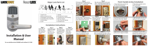
Front Handle & Key Installation1. Ensure that the key override slot is in the horrizontal position.2. Slide the key cylinder into the back of the handle.3. Insert the key into the key cylin-der from the front of the handle.4. Slide the handle onto the drive shaft until it hits the catch pins.5. Push the key in as far as it will go and then turn 90 degrees clockwise.6. Firmly press the lever until it snaps over the catch pins. Turn thekey back to the left and remove.Step 5Fit the front lock housing onto thefront of the door. Feed the power plugthrough the 2 1/8” boring hole.Step 6Place the inside gasket on the insideplate. Feed power plug through andsecure to door & front lock with screw.Step 7Hold the inside lock housing up tothe inside of door. Plug the front lockpower cable into the connector.Step 8Place inside lock overmounting place &secure with screws.Step 9Insert 4 AA batteriesinto the batterycompartment.Step 10Secure the inside lock housingbattery cover with two screws.Step 11Slide the inside lever into place. Pressrmly until handle snaps over catch pins.Major Lock Parts ListInstallation InstructionsStep 1Insert latch intothe door latchhole. Secure thelatch with twoscrews.Step 2Drill the 3/8” uppersupport hole intothe door 3 5/16”above the centerof boring hole.Step 4Insert the squarespindle into thecenter hub.Ensure dot ispointed left.Step 3Place the frontside rubber gasket(if required) on theback of the frontlock housing.Installation & UserManualFor use with ResortLock® RL4000 and LockState® LS-1500®Complete List ofManual Programming Functions1. To set a new or change the Master Code (and not delete existing user codes):# current or default mc # 11 # 1-9 digit new mc # 1-9 digit new mc #2. To change Master Code (and delete all user codes):# current or default mc # 22 # 1-9 digit new mc # 1-9 digit new mc #3. Set date & time - (24 hr. clock, Example: 2:45PM on July 12, 2010 = 1007121445) # mc # 88 # yymmddhhmm #4. Enter one or more User Code with no restriction (for multiple users, repeat highlighted) # mc # 01 # 1-9 digit user code # # #5. Enter one or more iButton key with no restriction (for multiple users, repeat highlighted)# mc # 01 #Hold iButton key to lock reader # #6. Enter one or more iButton key + User Code with no restriction (for multiple users, repeat highlighted)# mc # 01 # 1-9 digit user code # Hold iButton key to lock reader# #7. Enter one or more User Code with time restriction (for multiple users, repeat highlighted)(beginning time) (ending time) # mc # 01 # 1-9 digit user code # yymmddhhmm # yymmddhhmm #8. Enter one or more iButton key with time restriction (for multiple users, repeat highlighted)(beginning time)(ending time)# mc # 01 # iButton key yymmddhhmm # yymmddhhmm #9. Enter one or multiple iButton + User Codes with time restriction (for multiple, repeat highlighted)(beginning time) (ending time) # mc # 01 # 1-9 digit code # iButton key yymmddhhmm # yymmddhhmm #10. Enable Passage Mode(1=Monday, 7=Sunday)# mc # 15 # 1-7 Schedule # hhmm start hhmm end #11. Disable Passage Mode12. Enable/ disable LED blink (2 beeps = blink o ~ 4 beeps = blink on)*Warning: enabling blink mode will drain batteries more quickly.Lock will blink red when locked, green when unlocked.# mc # 16 # # mc # 18 # (for multiple users, repeat highlighted)(for multiple users, repeat highlighted) *A User Code or iButton must be programmed before Advanced Schedule Access can be applied.13.Enable Daylight Saving Time# mc # 31 #* Lock time does not change when you enable this function. The time will change according to the U.S. Daylight Saving Time schedule.14.Disable Daylight Saving Time # mc # 32 #15.Add One Time Service codes (up to 10) (for multiple users, repeat highlighted) # mc # 33 # 1-9 digit user code #16. Delete one User Code or iButton user # mc # 46 # User code or touch iButton #17. Enable Auto-UNlock function # mc # 64 #18. Disable Auto-UNlock function # mc # 65 #19.Set Automatic Unlock time (Enable function #17 rst) # mc # 63 # hhmm #20. Enable Auto-Lock function # mc # 67 #21. Disable Auto-Lock function # mc # 68 #22.Set Automatic Lock time (Enable function #20 rst) # mc # 66 # hhmm #23. Enable/Disable temporary lockout of all users #mc# 99#Advanced Schedule Access 24. Set schedule for User Code: (1=Monday, 7=Sunday)# mc # 45 # 1-9 digit User Code # 1-7 Schedule # hhmm start hhmm end #25.Set schedule for iButton user: (1=Monday, 7=Sunday) # mc # 45 # iButton key # 1-7 Schedule #hhmm start hhmm end #For Example: to set schedule from 8:00AM to 5:00PM, Mon. to Friday# mc # 45 # 1-9 digit User Code # 12345 # 0800 1700 #Lock Operation GuideGeneral Information:• Door Handle: The handle is reversible so it will t both right and left-handed doors. Thehandle will always turn even when the door is locked. However, when locked, the exterior handle will not retract the latch. The interior handle will always retract the latch.• Exit Programming Mode: Enter * to exit programming mode, or wait for 10 seconds.• Low battery warning: When batteries are low, the red LED will ash and beep ve times afterentering a valid User Code.• Unlocking indicator: Green light will ash and beep twice.• Locking indicator: No light and will beep twice.• Reset: To reset the lock back to factory default settings, press and hold the reset button for 10 seconds until the light on the front of the lock starts ashing green. Release the reset button and press the # key to con rm. You will receive 3 beeps if successful.Manufacture Default Setting:• Daylight Saving Mode: Disabled • Auto Lock/Unlock: Disabled • Lock Mode: Storehouse • Default Programming Master Code: 123456• Test Code: 0 #Unlocking the Door:There are several ways to unlock the lock, including the following methods:• Keycode: Enter a User Code, then press #• iButton: Touch the iButton key to the lock reader• iButton+Keycode: Touch the iButton key to the lock reader, then enter User Code and press #• One time service code: Enter one time code, then press #• Manual key: Insert and turn the override key 90 degrees clockwise, then turn the handleTerms:Master Code (MC): The master code enters the lock into programming mode. It will not lock or unlock the lock the door. If more than 6 seconds pass in between programming entries, the lock will return to normal operational status. For maximum security change the default Master er code: User Codes are the normal codes for day-to-day operation.Service Code: Service codes can be used for maintenance personnel or vendors. Service codes only grant one-time access. A total of 10 sets of service codes can be programmed into each lock.Passage Mode: When Passage Mode is enabled, the lock will stay in an unlocked status after a valid entry code is entered. Enter a valid entry code to re-lock the door.Storehouse Mode: For each valid entry, the lock will automatically re-lock after 5 seconds.Time Format: 24 hr. clock ~ 8:30AM = 0830; 5:30PM = 1730 Schedule Date: 1=Mon, 2=Tue, 7=SunQuick Start GuideStep 1: Program a new Master Code into the lock.The Master Code DOES NOT unlock or lock the door. It is only used to program your lock. The default Master Code is 123456. For security purposes, you will need to change this to your own Master Code. Decide on a new Master Code and write it here: _____________To program a new Master Code, enter the following into the lock’s keypad:# 123456 # 11 # Your Master Code # Your Master Code Again #If done correctly , after the last # you press you’ll hear 2 beeps with 2 green ashes.Step 2: Program the Date & Time.Some functions on the lock will not work on the lock unless the date & time are programmed. Toprogram the date & time, enter the following:# Master Code # 88 # YYMMDDHHMM #Example: If the date and time is 05/30/2010 at 3:32PM, you would enter:# Master Code # 88 # 1005301532 #Step 3: Program a User Code into the lock.**Important: Your lock will not lock until a valid User Code is programmed and used on the er Codes are the codes you will use to unlock and lock your door. These codes will remain active in the lock until they are deleted (if desired). Up to 800 permanent codes can be programmed into the lock. Here is how:# Master Code # 01 # 1-9 digit user code # # # #If done correctly , you will hear two beeps after pressing the 3rd #, then a red light after the 4th #.Step 4: Set the Passage Mode. (Optional)Your lock is shipped in Storehouse Mode. This means the lock will re-lock 5 seconds after it is unlocked. To change this to passage mode, enter the following:# Master Code # 15 # 1-7 Schedule # hhmm start, hhmm end #Example: If you want the lock to always be in Passage Mode, enter:# Master Code # 15 # 1234567 # 0001 2359 # (7 days of the week from 12:01AM to 11:59PM)Step 5: Enable Daylight Saving Time.If you live in an area that observes Daylight Saving Time, you will want to enable this function. Enabling does not change the current time on the lock. The time wil change according to the U.S. Daylight Saving Time schedule. To enable, enter:# Master Code # 31 ## # # # # #。
ODIS系统安装、更新及蓝牙匹配
2、 离线安装 点击“选择本地目录”,选择ODIS 光盘驱动器(例如 “E:\”)
57
ODIS的post-setup安装
1. 确定基础安装包放在哪个Odis文件夹下(dav或者Odis_SVW)。 2. 将浏览器中的地址(看到Odis文件夹的地址)复制到安装中的URL栏。
点击向右箭头
58
ODIS的post-setup安装
https://portal.cpn.vwg/
8
使用eShop申请ODIS证书流程
点击左边的“订购”或者右边的“产品”图标
9
使用eShop申请ODIS证书流程
点击右侧图标(添加到购物篮)
10
使用eShop申请ODIS证书流程
点击右侧图标(添加到购物篮)
11
使用eShop申请ODIS证书流程
点击右侧图标(添加到购物篮)后等待几秒钟, 等网页刷新后点击右下角“转到购物篮”。
12
使用eShop申请ODIS证书流程
点击右下角“转到订购”
13
使用eShop申请ODIS证书流程
请关闭所有杀毒软件和360卫士 等防护软件后点击钥匙状图标
14
使用eShop申请ODIS证书流程
点击“运行”
15
使用eShop申请ODIS证书流程
继续点击“运行”
16
使用eShop申请ODIS证书流程
先在“我接受AGB”处打勾,然后填写自己的电子邮 件地址,最后点击右下角“检查订购”。
22
使用eShop申请ODIS证书流程
如资料填写无误,点击“订购”。
23
使用eShop申请ODIS证书流程
出现此页面说明订购已完成,可以打印订单,此时维 修站将会收到一封确认邮件。
蓝牙适配器下载安装教程+听歌聊Q教程+常见错误及解决教程
(三)、史上最详细蓝牙耳机,听音乐,聊QQ系列教程(查看图解教程),
========使用蓝牙耳机常见错误及解决办法========
(一)、蓝牙耳机不开机?
错误:按错地方
解决办法:看说明书(通常是带的电话标志那个)
(二)、蓝牙耳机充电接触不良?
错误:没看我们发货后在旺旺中留言过的《蓝牙使用指南》
1、错误:没有重启电脑,蓝牙传输文件服务、蓝牙耳机服务没被电脑识别。
解决办法:重启电脑
2、错误:装驱动之前先插适配器,导致无法安装时正常替换微软签名的驱动。
解决办法:先卸载驱动,然后记得先不插蓝牙适配器,重装驱动软件后重启电脑。
3、错误:安装过程中出现错误提示,但继续安装
1、错误:安装的IVT 2.6版本与电脑XP系统(SP2、SP3版本)自带的蓝牙驱动冲突,系统自动保护文件,无法替换驱动。
解决办法:将原IVT 2.6驱动卸载干净,重新安装千月版本,后重启电脑。
(九)、使用IVT 2.6版本驱动,播放音乐时,可以控制上下曲,但蓝牙耳机无声音?
1、错误:原因不明。
(二)、点中间圆球搜索,能搜索到手机,但是搜索不到蓝牙耳机?
1、错误:没有重启电脑,蓝牙传输文件服务、蓝牙耳机服务没被电脑识别。
解决办法:重启电脑
2、错误:蓝牙耳机只是开机,但没开到配对状态
解决办法:将蓝牙耳机开到配对状态,再进行搜索
(三)、点中间圆球搜索,手机与蓝牙都搜索不到,或者偶尔能搜索到但连接不上?
(四)、点中间圆通搜索,搜索到蓝牙耳机后,配对不上?
1、错误:蓝牙耳机开到配对状态后,长时间没配对,导致超时配对失败
解决办法:将蓝牙耳机开到配对状态后,再进行搜索及配对
蓝牙培训文档资料汇总PPT(27张)

手机与耳机对比
手机 接听 挂断 拨打 重拨 拒接 *切换
耳机 开启语音识别拨号 接听 挂断 重拨 拒接 *切换
手机之间的文件传输
手机蓝牙开启并处于可见状态 蓝牙传输的一些接口(例如768:联系人、名 片识别、酷派播放、铃声宝库、数码图册等等) 注意一点的是手机之间的文件传输走的是OPP 服务,而并非是FTP服务
蓝牙的一些相关知识
蓝牙认证 蓝牙认证将使OEM的产品列入蓝牙官方网站,并允许他们在产品 中使用蓝牙商标。认证可以帮助不同厂商的蓝牙产品实现互通并 使其符合蓝牙规范。认证流程可以分为以下四个部分:无线链路 需求、协议需求、概要需求和信息需求。 整个认证流程完全由蓝牙品质认证委员会 (Bluetooth Qualification Review Board, BQRB)监控和管理。认证基于一套参考测试系统 的一致性测试(由蓝牙认证流程(BQP)制订)以及与其他符合标准的 蓝牙产品之间的互通性测试。测试由已得到SIG下属的 BQRB授权 的蓝牙认证测试部门(BQTF)实施。 除了测试,希望得到认证的生产商还需要提交承诺声明,蓝牙认 证组织(BQB)将审查该声明。此外,除了获得BQB的认证外,蓝 牙产品还需要获得其他一些认证,如FCC和CE。
蓝牙的保存问题
保存一般有两种:指定保存路径和默认保存路 径 指定保存路径是指弹出保存框,用户可以自己 选择保存的地方 默认保存路径是指传输完成后,会弹出一个提 示框出来,告诉用户已经保存在哪,有时也不 会弹出提示框出来
蓝牙的保存问题
蓝牙保存的格式:一般是按原有格式来保存的。 但要注意两点: 1、有一些文件传输过后保存的格式是Vcard, 后缀名为.vcf,它默认的保存路径是在联系人 (通讯簿)中。例如联系人,名片识别、发送 名片、接收名片、交换名片等 2、文件从一台手机传输到另一台手机后,不 一定在另一台手机上能够打开此文件,主要原 因是格式不支持
《蓝牙手持机APP系统V1.0》 操作手册

蓝牙手持机APP系统用户操作手册重庆英卡电子有限公司2015.2目录1概述 (1)2系统特点 (1)3操作说明 (1)3.1进入 (1)3.2预警监控 (2)3.3节点管理 (4)3.3.1节点配置 (4)3.3.2节点查询 (6)3.3.3模拟预警 (7)3.4安装维护 (8)3.4.1通信测试 (8)3.5连接管理 (9)3.5.1连接蓝牙设备 (9)3.5.2断开蓝牙设备连接 (13)3.6更多设置 (14)3.6.1盒子RF配置设置 (15)3.6.2盒子RF配置查询 (16)3.6.3报警设置 (17)3.7系统退出 (18)1概述蓝牙手持机APP系统主要是通过手机蓝牙通讯功能连接专用蓝牙设备,蓝牙设备与探测器之间进行通信,这样用户的手机就可以直接配置和接收探测器节点信息,实现探测器的测试、管理、查询等检查及维护管理功能,从而取代专用的手持机设备和软件。
蓝牙手持机APP系统包括预警监控、节点配置、节点查询、模拟预警、通信测试、连接管理、蓝牙设备的配置设置和查询等功能。
其系统主要功能为:(1)预警监控:预警监控、消警、历史预警记录查看与清空等功能。
(2)节点管理:节点配置、节点查询、模拟预警、历史记录查看与清空等功能。
(3)安装维护:通信测试、历史记录等功能。
(4)连接设备:搜索蓝牙设备、连接管理等功能。
(5)更多设置:盒子RF配置设置、盒子RF配置查询、报警设置功能。
2系统特点(1)预警提示:只要探测器给手机发送预警警报,用户在软件任意界面都会接收到预警提示对话框,便于用户及时查看和处理预警信息。
(2)手机蓝牙:当用户打开该软件后,如果用户没有开启蓝牙功能,则自动开启手机蓝牙,并且在退出系统后自动关闭蓝牙功能;如果用户已经开启蓝牙,则退出系统不会关闭蓝牙功能,保持用户手机的状态不作改变。
(3)蓝牙自动连接与断开:当该软件在手机后台运行或手机关屏等操作时,30秒后蓝牙会自动断开;当用户重新唤醒软件则自动连接蓝牙。
蓝牙基础知识培训ppt课件

蓝牙应用
行业应用
■蓝牙广告传媒系统蓝牙广告传媒,顾名思义,就是以蓝牙技术为依托,将信息 有效地传递到蓝牙的终端载体——手机,有专家称其为“第五媒体”。 “蓝 牙广告传媒”以蓝牙技术在精确距离无线发送多媒体数据,在传输过程并不 会产生任何的费用。作为一种新媒体,蓝牙媒体可以集图形、图像、声音、 文字、视频、动画等多种信息表现形式于一身,在终端手机上一一得到完美 展现。 由于蓝牙的最大特点就是具有自发传播性。手机终端不仅可以接收广告 内容,还可以将广告内容向周围转发。传统的广告只能通过消费者口口相传, 才能达到消费者自发传播的效果,且传播过程中难免会存在信息失真。借助 于先进的通信手段,消费者可以将手机蓝牙广告转发给其他潜在客户,有利 于广告内容在潜在消费者中的准确迅速传播。 蓝牙广告传媒系统由于明确了广告的具体受众类型,将广告直接送达目 标人群,在向用户发送广告内容的过程中,不仅可以记录用户的手机号码和 现场行为,还可通过跟踪记录客户消费信息,甚至直接同消费者通信,准确 获知广告效果。 比如火车站,机场设置基站,提供客运时刻表相关信息;商 场基站提供促销活动信息并提供产品目录与导购服务;医院基站则提供药品 价格专家就诊日程等等。
■TCS是一个基于ITU-T Q.931建议的采用面向比特的协议,它定义了用于蓝牙设备之 间建立语音和数据呼叫的控制信令(Call Control Signalling),并负责处理蓝牙 设备组的移动管理过程。
11 11页
蓝牙体系结构
高端应用层 — 组成 高端应用层由选用协议层组成。可选用的协议PPP 、TCP/IP、OBEX(Object
Exchange Protocol)、WAP(Wireless Application Protocol)、WAP(Wireless Application Protocol)
一体机功能操作指引PPT

一体机加密界面隐藏
• 进入一体机《硬件通讯密码》界面,如下图
按图示操 作管理卡
下一步 点隐藏,会提示一 个方框,如下图
点:是
按提示操作并 重新登录软件
重启软件
硬件通讯密码已隐藏,直接 在键盘上盲打出BLUETOOTH (恢复密码),重新登录即可恢复 注意:键盘语言输入法要设为EN(英文)
一体机功能设置
• 进入<一体机设置界面>:一体机功能设置只需要完成4步,1: 加密 2:校时 3:设置机号 4:加载收费标准(月卡/临时卡) • 第一步:前面已经介绍,在此不再重复 • 第二步:校时,如下图所示 • 、
拿着管理卡,对着一体机发卡 器(如左图),点“制卡“,校时 信息会自动上传并储存到管理卡, 拿着管理卡对着一体机按一下即可
注意: 发卡器会自动检测有没有卡在上面,5秒后检测仍无卡,加密工作会自动停止,再次点击 加密即可!
修改卡片密码
• 进入《硬件通讯密码》界面 找到”卡片清除密码“功能
输入旧密码,把卡片放到发卡 器上点清除即可,软件右上角 会提示密码清除成功 并带有语音提示
卡片发行
进入《卡片发行》界面:卡片发行顺序,1:增加 2:输入卡号 3:卡类选择 4:卡 片有效期 5:出入权限 6业主信息 7:点左上角”保存“ 8:点击:“发行卡片” 7 8 (完成)
• 设置机号、加载收费标准也是一样的操作,管理卡相当于一个 无线传递数据的卡片(注意:下传第二条信息,会把第一条信 息全部覆盖,卡片内会保留最新上传的信息)
第 三 部分
卡片发行、延期,退卡, 挂失,解挂
温馨提示: 为了保障你的权益,一体机卡片请加密后再交给你的客户!
卡片加密
1:修改软件密码:前面已经讲过,不再重复 2:卡片加密: 进入硬件通讯密码界面,如下图 把卡片放到发卡器上 (亮灯区域),点加密即 可,右上角显示并带有语 音提示:卡片加密已成 功(可连续加密) 下一步
戴尔 Precision 7820 塔式机无线蓝牙模块安装指南说明书

Dell Precision 7820 T owerWi-Fi Bluetooth Module Installation GuideNotes, cautions, and warningsNOTE: A NOTE indicates important information that helps you make better use of your product.CAUTION: A CAUTION indicates either potential damage to hardware or loss of data and tells you how to avoid the problem.WARNING: A WARNING indicates a potential for property damage, personal injury, or death.© 2019 Dell Inc. or its subsidiaries. All rights reserved. Dell, EMC, and other trademarks are trademarks of Dell Inc. or its subsidiaries. Other trademarks may be trademarks of their respective owners.2019 - 02Rev. A001 Before you begin (4)Safety instructions (4)Before working inside your computer (4)Safety precautions (5)Electrostatic discharge—ESD protection (5)ESD field service kit (6)Transporting sensitive components (7)After working inside your computer (7)2 Wi-Fi Bluetooth (8)Wi-Fi Bluetooth Module installation kit (8)Installing the Wi-Fi Bluetooth Module for Precision 7820 Tower (8)3 Getting help (20)Contacting Dell (20)Contents3Before you begin Safety instructionsUse the following safety guidelines to protect your computer from potential damage and to ensure your personal safety. Unless otherwise noted, each procedure included in this document assumes that the following conditions exist:•You have read the safety information that shipped with your computer.•A component can be replaced or, if purchased separately, installed by performing the removal procedure in reverse order. WARNING: Disconnect all power sources before opening the computer cover or panels. After you finish working inside thecomputer, replace all covers, panels, and screws before connecting to the power source.WARNING: Before working inside your computer, read the safety information that shipped with your computer. For additional safety best practices information, see the Regulatory Compliance HomepageCAUTION: Many repairs may only be done by a certified service technician. You should only perform troubleshooting and simple repairs as authorized in your product documentation, or as directed by the online or telephone service and support team.Damage due to servicing that is not authorized by Dell is not covered by your warranty. Read and follow the safety instructions that came with the product.CAUTION: T o avoid electrostatic discharge, ground yourself by using a wrist grounding strap or by periodically touching an unpainted metal surface at the same time as touching a connector on the back of the computer.CAUTION: Handle components and cards with care. Do not touch the components or contacts on a card. Hold a card by its edges or by its metal mounting bracket. Hold a component such as a processor by its edges, not by its pins.CAUTION: When you disconnect a cable, pull on its connector or on its pull-tab, not on the cable itself. Some cables have connectors with locking tabs; if you are disconnecting this type of cable, press in on the locking tabs before you disconnect the cable. As you pull connectors apart, keep them evenly aligned to avoid bending any connector pins. Also, before you connect acable, ensure that both connectors are correctly oriented and aligned.NOTE: The color of your computer and certain components may appear differently than shown in this document.CAUTION: System will shut down if side covers are removed while the system is running. The system will not power on if the side cover is removed.Before working inside your computer1 Ensure that your work surface is flat and clean to prevent the computer cover from being scratched.2 Turn off your computer.3 Disconnect all network cables from the computer (if available).CAUTION: If your computer has an RJ45 port, disconnect the network cable by first unplugging the cable from yourcomputer.4 Disconnect your computer and all attached devices from their electrical outlets.5 Open the display.6 Press and hold the power button for few seconds, to ground the system board.CAUTION: To guard against electrical shock unplug your computer from the electrical outlet before performing Step #8.CAUTION: To avoid electrostatic discharge, ground yourself by using a wrist grounding strap or by periodically touchingan unpainted metal surface at the same time as touching a connector on the back of the computer.1 4Before you begin7 Remove any installed ExpressCards or Smart Cards from the appropriate slots.Safety precautionsThe safety precautions chapter details the primary steps to be taken before performing any disassembly instructions.Observe the following safety precautions before you perform any installation or break/fix procedures involving disassembly or reassembly:•Turn off the system and all attached peripherals.•Disconnect the system and all attached peripherals from AC power.•Disconnect all network cables, telephone, and telecommunications lines from the system.•Use an ESD field service kit when working inside any desktop to avoid electrostatic discharge (ESD) damage.•After removing any system component, carefully place the removed component on an anti-static mat.•Wear shoes with non-conductive rubber soles to reduce the chance of getting electrocuted.Standby powerDell products with standby power must be unplugged before you open the case. Systems that incorporate standby power are essentially powered while turned off. The internal power enables the system to be remotely turned on (wake on LAN) and suspended into a sleep mode and has other advanced power management features.Unplugging, pressing and holding the power button for 15 seconds should discharge residual power in the system board. . BondingBonding is a method for connecting two or more grounding conductors to the same electrical potential. This is done through the use of a field service electrostatic discharge (ESD) kit. When connecting a bonding wire, ensure that it is connected to bare metal and never to a painted or non-metal surface. The wrist strap should be secure and in full contact with your skin, and ensure that you remove all jewelry such as watches, bracelets, or rings prior to bonding yourself and the equipment.Electrostatic discharge—ESD protectionESD is a major concern when you handle electronic components, especially sensitive components such as expansion cards, processors, memory DIMMs, and system boards. Very slight charges can damage circuits in ways that may not be obvious, such as intermittent problems or a shortened product life span. As the industry pushes for lower power requirements and increased density, ESD protection is an increasing concern.Due to the increased density of semiconductors used in recent Dell products, the sensitivity to static damage is now higher than in previous Dell products. For this reason, some previously approved methods of handling parts are no longer applicable.Two recognized types of ESD damage are catastrophic and intermittent failures.•Catastrophic – Catastrophic failures represent approximately 20 percent of ESD-related failures. The damage causes an immediate and complete loss of device functionality. An example of catastrophic failure is a memory DIMM that has received a static shock and immediately generates a "No POST/No Video" symptom with a beep code emitted for missing or nonfunctional memory.•Intermittent – Intermittent failures represent approximately 80 percent of ESD-related failures. The high rate of intermittent failures means that most of the time when damage occurs, it is not immediately recognizable. The DIMM receives a static shock, but the tracing is merely weakened and does not immediately produce outward symptoms related to the damage. The weakened trace may take weeks or months to melt, and in the meantime may cause degradation of memory integrity, intermittent memory errors, etc.The more difficult type of damage to recognize and troubleshoot is the intermittent (also called latent or "walking wounded") failure. Perform the following steps to prevent ESD damage:Before you begin5•Use a wired ESD wrist strap that is properly grounded. The use of wireless anti-static straps is no longer allowed; they do not provide adequate protection. T ouching the chassis before handling parts does not ensure adequate ESD protection on parts with increased sensitivity to ESD damage.•Handle all static-sensitive components in a static-safe area. If possible, use anti-static floor pads and workbench pads.•When unpacking a static-sensitive component from its shipping carton, do not remove the component from the anti-static packing material until you are ready to install the component. Before unwrapping the anti-static packaging, ensure that you discharge static electricity from your body.•Before transporting a static-sensitive component, place it in an anti-static container or packaging.ESD field service kitThe unmonitored Field Service kit is the most commonly used service kit. Each Field Service kit includes three main components: anti-static mat, wrist strap, and bonding wire.Components of an ESD field service kitThe components of an ESD field service kit are:•Anti-Static Mat – The anti-static mat is dissipative and parts can be placed on it during service procedures. When using an anti-static mat, your wrist strap should be snug and the bonding wire should be connected to the mat and to any bare metal on the system being worked on. Once deployed properly, service parts can be removed from the ESD bag and placed directly on the mat. ESD-sensitive items are safe in your hand, on the ESD mat, in the system, or inside a bag.•Wrist Strap and Bonding Wire – The wrist strap and bonding wire can be either directly connected between your wrist and bare metal on the hardware if the ESD mat is not required, or connected to the anti-static mat to protect hardware that is temporarily placed on the mat. The physical connection of the wrist strap and bonding wire between your skin, the ESD mat, and the hardware is known as bonding. Use only Field Service kits with a wrist strap, mat, and bonding wire. Never use wireless wrist straps. Always be aware that the internal wires of a wrist strap are prone to damage from normal wear and tear, and must be checked regularly with a wrist strap tester in order to avoid accidental ESD hardware damage. It is recommended to test the wrist strap and bonding wire at least once per week.•ESD Wrist Strap Tester – The wires inside of an ESD strap are prone to damage over time. When using an unmonitored kit, it is a best practice to regularly test the strap prior to each service call, and at a minimum, test once per week. A wrist strap tester is the best method for doing this test. If you do not have your own wrist strap tester, check with your regional office to find out if they have one.T o perform the test, plug the wrist-strap's bonding-wire into the tester while it is strapped to your wrist and push the button to test. A green LED is lit if the test is successful; a red LED is lit and an alarm sounds if the test fails.•Insulator Elements – It is critical to keep ESD sensitive devices, such as plastic heat sink casings, away from internal parts that are insulators and often highly charged.•Working Environment – Before deploying the ESD Field Service kit, assess the situation at the customer location. For example, deploying the kit for a server environment is different than for a desktop or portable environment. Servers are typically installed in a rack within a data center; desktops or portables are typically placed on office desks or cubicles. Always look for a large open flat work area that is free of clutter and large enough to deploy the ESD kit with additional space to accommodate the type of system that is being repaired. The workspace should also be free of insulators that can cause an ESD event. On the work area, insulators such as Styrofoam and other plastics should always be moved at least 12 inches or 30 centimeters away from sensitive parts before physically handling any hardware components•ESD Packaging – All ESD-sensitive devices must be shipped and received in static-safe packaging. Metal, static-shielded bags are preferred. However, you should always return the damaged part using the same ESD bag and packaging that the new part arrived in.The ESD bag should be folded over and taped shut and all the same foam packing material should be used in the original box that the new part arrived in. ESD-sensitive devices should be removed from packaging only at an ESD-protected work surface, and parts should never be placed on top of the ESD bag because only the inside of the bag is shielded. Always place parts in your hand, on the ESD mat, in the system, or inside an anti-static bag.•Transporting Sensitive Components – When transporting ESD sensitive components such as replacement parts or parts to be returned to Dell, it is critical to place these parts in anti-static bags for safe transport.ESD protection summaryIt is recommended that all field service technicians use the traditional wired ESD grounding wrist strap and protective anti-static mat at all times when servicing Dell products. In addition, it is critical that technicians keep sensitive parts separate from all insulator parts while performing service and that they use anti-static bags for transporting sensitive components.6Before you beginTransporting sensitive componentsWhen transporting ESD sensitive components such as replacement parts or parts to be returned to Dell, it is critical to place these parts in anti-static bags for safe transport.Lifting equipmentAdhere to the following guidelines when lifting heavy weight equipment:CAUTION: Do not lift greater than 50 pounds. Always obtain additional resources or use a mechanical lifting device.1Get a firm balanced footing. Keep your feet apart for a stable base, and point your toes out.2Tighten stomach muscles. Abdominal muscles support your spine when you lift, offsetting the force of the load.3Lift with your legs, not your back.4Keep the load close. The closer it is to your spine, the less force it exerts on your back.5Keep your back upright, whether lifting or setting down the load. Do not add the weight of your body to the load. Avoid twisting your body and back.6Follow the same techniques in reverse to set the load down.After working inside your computerAfter you complete any replacement procedure, ensure that you connect external devices, cards, and cables before turning on your computer.CAUTION: T o avoid damage to the computer, use only the battery designed for this particular Dell computer. Do not use batteries designed for other Dell computers.1 Connect any external devices, such as a port replicator or media base, and replace any cards, such as an ExpressCard.2 Connect any telephone or network cables to your computer.CAUTION: To connect a network cable, first plug the cable into the network device and then plug it into thecomputer.3 Connect your computer and all attached devices to their electrical outlets.4 Turn on your computer.Before you begin7Wi-Fi BluetoothWi-Fi Bluetooth Module installation kitThe following components are required to install the Wi-Fi/ Bluetooth (BT) module:1Wi-Fi/BT PCIe adapter card 2Wi-Fi card screw 3Wi-Fi card bracket 4Wi-Fi card 5Wi-Fi/BT PCIe adapter card cable 6External antenna7Plastic cover Installing the Wi-Fi Bluetooth Module for Precision 7820 T ower1Follow the procedure in before working inside your computer .2 T o install the Wi-Fi card into the Wi-Fi/Bluetooth (BT) PCIe adapter card:aAlign and insert the Wi-Fi card into the slot on the Wi-Fi/BT PCIe adapter card [1].bConnect the antenna cables to the Wi-Fi card [2].cAlign the Wi-Fi card bracket on the Wi-Fi card [3].d Tighten the single screw (M2x2.5) to secure both the Wi-Fi card bracket and Wi-Fi card to the Wi-Fi/BT PCIe adapter card [4].28Wi-Fi BluetoothWi-Fi Bluetooth94 To remove the side cover:a Press the latch.10Wi-Fi BluetoothWi-Fi Bluetooth115 To remove the PCIe card holder:•If full length cards are installed, you will need to remove these cards before removing the holder.•If MegaRAID 9460 is installed, disconnect the Super CAP from the card before removing the PCIe card holder from the system.a Disconnect the two power cables from the cable slot in the PCIe holder [1].b Press the PCIe holder securing clip and slide the holder [2] out of the chassis.12Wi-Fi Bluetooth6 To remove the filler bracket:a Press and rotate the PCI latch backward [1] to unlock the filler bracket.b Remove the filler bracket from the slot on the system [2].Wi-Fi Bluetooth1314Wi-Fi Bluetooth8 To connect the Wi-Fi/BT PCIe adapter card cable:a Lock both the PCI latch brackets forward on the filler bracket to secure the Wi-Fi/BT PCIe adapter card to the system board [1].b Route the Wi-Fi/BT PCIe adapter card cable through to the routing channels on the system [2].c Connect other end of the Wi-Fi/BT PCIe adapter card cable socket to the connector on the system board [3].Wi-Fi Bluetooth159 To install the PCIe holder:a Align and place the PCIe holder to the system chassis [1]. Then, press the holder back until it clicks to the system.b Connect the two power cables to the cable slots in the holder [2].•If the MegaRAID 9460 was removed, please connect the Super CAP back to the card.•Reinstall the full length cards if they were removed.16Wi-Fi BluetoothWi-Fi Bluetooth1711 To install the external antenna:a Pass the external antenna cables through the openings on the plastic cover [1].b Fasten antenna cables to Wi-Fi/BT PCIe adapter card [2].c Tighten the single screw to secure the plastic cover to the PCI panel [3].18Wi-Fi BluetoothWi-Fi Bluetooth19Getting helpContacting DellNOTE: If you do not have an active Internet connection, you can find contact information on your purchase invoice, packing slip, bill, or Dell product catalog.Dell provides several online and telephone-based support and service options. Availability varies by country and product, and some services may not be available in your area. T o contact Dell for sales, technical support, or customer service issues:1Go to /support.2Select your support category.3Verify your country or region in the Choose a Country/Region drop-down list at the bottom of the page.4 Select the appropriate service or support link based on your need.320Getting help。