箱变安装使用说明书(中英文)
220KV级变压器安装使用说明书 中英文

Instruction Manual of Installation and Operationfor220kV Power Transformer目录Content1.适用范围 (3)Applicable Scope (3)2.运输及起吊 (3)Lifting and transportation of transformer main body (3)2.1运输要求 (3)Transportation Requirements (3)2.2主体运输 (4)Transportation of Transformer Main Body (4)2.3主体起吊 (4)Lifting of Main Body (4)2.4主体牵引 (5)Traction of Main Body (5)3.验收和保管贮存 (5)Acceptance and Storage (5)3.1到货验收 (5)Acceptance after Transformer Arrival (5)3.2附件开箱检查验收 (6)Inspection and Check of Accessories’ Boxes (6)3.3保管及贮存 (6)Storage (6)3.4 绝缘油的管理 (7)Insulation Oil (7)4.整体复装 (8)Re-assembly (10)4.1整体复装的注意事项 (10)Notes for Re-assembly (10)4.2组装前的准备工作 (11)Preparations before re-assembly (11)4.3整体复装 (11)Transformer re-assembly (11)5.真空注油 (13)Vacuum oil-filling (13)5.1真空注油 (13)Vacuum oil-filling (13)5.2补充注油及静放 (15)Supplementary oil-filling and placing still (15)6.交接试验和试运行 (16)Site Acceptance test and Commission (16)6.1试验前的检查 (16)Check before Site Acceptance Test (16)6.2交接试验 (17)Site Acceptance Test (17)6.3 试运行前的检查 (17)Inspection before Trial Operation (17)6.4投入试运行 (18)Put into trial operation (18)7.运行维护 (19)Maintenance in (service) operation (19)7.1正常运行 (19)Normal operation (19)7.2维护 (20)Maintenance (20)7.3变压器故障分析和排除 (21)Analysis and elimination of transformer faults (21)7.4螺栓紧固外加(最大)力矩 (23)1. 适用范围Applicable Scope本说明书适用于220kV油浸式电力变压器。
欧式箱变安装使用说明书

.YB-系列箱式变电站安装使用说明书安全第一!开关设备只能安装于适合电气设备工作的场所。
确保由专业人员来进行安装,操作和维护。
必须保证现场电气设备的联接条件及工作规程的适用性与安全性。
有关开关设备的一切操作,都应遵守本说明书的相应规定。
“危险”请特别注意说明书中标有此危险标志的注意事项。
不要超出开关设备在正常工作条件下的技术参数中规定的负载。
说明书应放在所有与安装,操作及维护有关的人员便于拿到的地方。
用户的专职人员应对所有影响工作安全的事项负责并正确使用开关设备。
警告:请自始至终遵守安装运行说明书规定和安全操作规程!危险电压可能引起电击和火灾在设备上进行任何作业前必须可靠切断电源若对本说明书尚有任何疑问,我们会及时详尽的为您提供资讯11 概述1.1 名称和型号本系列产品全称为YB系列组合式变电站。
产品型号:YB □—□ / □变压器额定容量KVA高压侧额定电压KV设计序号安装场所:户外组合式变电站2 使用条件2.1 海拔不超过1500m;2.2 环境温度:最高气温+50℃,最低气温-40℃(户外),最高日平均气温+30℃,最高年平均气温+20℃;2.3 户外风速不超过35m/s;2.4 空气相地湿度不超过90%(+25℃);2.5 地面倾斜度不大于30;2.6 地震加速度:水平不大于0.4m/s2,垂直不大于0.2m/s2。
2.7 安装地点无火灾、爆炸危险、化学腐蚀、剧烈振动,并且不应是低洼积水处,同时应留足组变开门所需空间。
2.8 本产品应安装在合适的基础上使用(请参阅5.1.1条);2.9 当环境条件超出上述规定范围,请与我公司联系,我们将根据具体要求,提供特殊设计的产品。
3 吊装及运输3.1 吊装3.1.1 本系列组变一般不应采用叉车搬运,户内产品可采用钢管垫底滚推的方法将产品就位,户外产品应使用吊机吊装就位。
3.1.2 吊装应按照有关起重安全规程进行,并应根据组变铭牌标称重量选择合适起吊设备。
110kV级及以上变压器安装操作说明书(英文版)
Content1. Introduction1.1 Scope of Application1.2 Product Type Specification1.3 Transformer Structure2. Transporting and Hoisting2.1 Requirement for Transporting2.2 Subject Transporting2.3 Subject Hoisting2.4 Subject Pulling and Lifting3. Acceptance and Storage3.1 Inspection of Merchandise Received3.2 OOBA Acceptance for Accessories3.3 Acceptance Storage3.4 Insulating Oil Management4. Installation and Inspection of Transformer4.1 Preparation for Transformer Inspection4.2 Conditions and Precautions for Transformer Inspection4.3 Scope of Transformer Inspection4.4 Test of Transformer Inspection5. Integral Compounded Installation and Vacuum Oil Filling5.1 Preparation for Installation5.2 Installation Program Flow5.3 Vacuum and Vacuum Oil Filling5.4 Replenishment and Standing5.5 Vacuum Oil Filling of Transformer without Inspection5.6 Installation of Other Components6. Pre-test Inspection and Acceptance Trial6.1 Pre-test Inspection6.2 Acceptance Trial7. Inspection Before Launch and Unload-energization7.1 Inspection Before Operation7.2 Unload Test7.3 Unload-energization8. Operation and Maintenance8.1 Operation8.2 Maintenance8.3 Transformer Failure Analysis and ClearanceⅠ. Introduction1.1 Scope of Application1.1.1 This specification is a document of technological guidance in installation and application, only applicable for oil-immersed transformer of 110kV (including off-circuit tap changing transformer, on load tap changing transformer, auto coupling transformer, and commutator transformer).1.1.2 Scope of Application: Requirements of transformer transporting by railway, road and ship; precautions for field acceptance and storage; field operation flow and acceptance trial; conditions for launch and daily maintenance; failure identification, etc.1.1.3 Application of this specification should be integrated with specific structure of transformer for proper construction according to relevant terms of technological requirements in the specification. For any question, please contact with the manufacturer for appropriate disposal. 1.2 Product Type Specification1.2.1 Type Specification for Oil-immersed Power TransformerS F S Z □ - □/□V oltage Class (kV)Nominal Capacity (kV A)Code of Performance LevelV oltage Regulation Mode:“Yes”means on load tap changing,“No”meansoff-circuit tap changingWinding No.:“Yes” means three windings, “No” means two windings.Cooling system: “Yes” means air cooling, “No” means self cooling.Three-phase transformer1.2.2 Type Specification for Immersed-type high-temperature-resistance power transformerS F S R N Z- □ /□V oltage Class (kV)Nominal Capacity (kV A)V oltage Regulation Mode:“Yes”means on load tap changing,“No”meansoff-circuit tap changingHigh temperature resistanceInsulating (cooling) medium is fire-resistant fluidWinding No.:“Yes” means three windings, “No” means two windings.Cooling system: “Yes” means air cooling, “No” means self cooling.Three-phase transformer1.3 Transformer Structure1.3.1 CoreThe core is wholly made of high permeability grain-oriented cold-reduced silicon sheet steel, automatically assembled by E-shape fully automated card stacker imported from Switzerland. The burr at sheared edge is no longer than 0.02mm. Appropriate set-up colligation is used for orientation of core leg so as to increase mechanical intensity and decrease open circuit losses and noises.1.3.2 CoilHigh-voltage coil is formed by interleaved continuous winding for small capacity and inner-screen continuous winding for large capacity in order to improve the voltage property under impulse voltage and reach even voltage distribution. The stay and bracket are all planed round edges to improve insulation reliability. Twist directed forced oil structure is designed inside transformer winding so that each part can be fully cooled to decrease the temperature rise of winding and its thermal point and prolong the insulation life. High and medium voltage regulator is equipped with individual regulating wingding so that each winding has balanced ampere-turn, and consequently to decrease the axial electromotion at short circuit of transformer and improve its capability to resist sudden short circuit. The winding radial is designed in “0” margin, keeping dry and close fitting between core and low-voltage winding cylinder, stay and boarding set, and among low-voltage, high-voltage and regulating winding so that the entire winding has great tightness and concentricity.1.3.3 Subject InsulationThe winding insulators, such as stay, bracket, and all high-voltage electrode and metal structural components, are planed round angles in order to avoid point discharge; the winding should undergo a second vacuum drying after completion of assembly, and the body shall have another kerosene gas drying, in which way the moisture content is greatly reduced from insulators and the body becomes more cleaner. Partial discharge of product is reduced through the technics mentioned above.1.3.4 LeadIn respect of high voltage lead, high-quality tapping switch is used for on-load tap changing, and the lead is connected by cold press with shielding process for round angle; for off circuit tap changing, single-phase off circuit tap changer is used.1.3.5 Oil ContainerThe transformer is equipped with a bell type tank and detachable finned radiator.Ⅱ. Transporting and Hoisting2.1 Requirement for Transporting2.1.1 Transformer transported with oil filling should be filled with qualified transformer insulating oil with the height of 150mm below the container top, and detach the radiator, conservator, moisture absorber, temperature controller and high and low voltage casing pipe and fan of 10000kV A and above, and make separated casing transportation, taking enough additional insulating oil along with subject transportation.2.1.2 Transformer transported with nitrogen fill shall be filled with nitrogen gas with 99% purity and a dew point no higher than -30℃. Besides, install a nitrogen-filling equipment and steam gage on top of the oil container, and keep the positive pressure inside container of 1.96~2.94×10⁴pa.2.1.3 Transportation loading should be carried according to the rules of relevant transportation department.2.1.4 During transportation, the impact recording instrument should be installed on the wall or cover of oil container. The measuring range is between ±1 and ±5g (g is the unit for acceleration of gravity), and the recording sensibility is 1.5~2 mm/g with 500-3000 times of recording.2.1.5 Transportation with on load tap changer must have oil filling in the height of at least 150mm lower than the container top.2.2 Subject Transporting2.2.1 During the whole process of transportation (despite of by railway, road or ship), the subject obliquity of no more than 15° in direction of long axis and no more than 10° in direction of short axis.2.2.2 Humping impact is prohibited. Acceleration of gravity for transportation: No more than 0.5g for axial acceleration, and no more than 0.3g for lateral acceleration.2.2.3 Less than 15km/h on first-class road, and less than 10km/h on second-class road.2.3 Subject Hoisting2.3.1 The hoisting equipments, tools and groundwork of loading site should be capable of bear the hoisting weight (transporting weight) of transformer.2.3.2 The angle of hoisting sling should be more than 30°.2.4 Subject Pulling and Lifting2.4.1 The working point of subject pulling should be hanging on the appropriate drawplate hole of bottom part of tank, not allowed to hang on such components incapable to bear weight as tube connector.2.4.2 The pulling speed of dolly or rollarounds on the track should be no more than 100m/h.2.4.3 For subject loading on slope, the slope angle should be less than 10° and the length more than 10m as well as with skidproof device.2.4.4 When using a screw jack, it should be place under the hoisting bracket. When lifting and landing, it should keep working in phase with the same speed, preventing the jack from skidding.Ⅲ. Acceptance and Storage3.1 Inspection of Merchandise Received3.1.1 Check and accept according to purchase order the products, nameplates, accessories and spare parts.3.1.2 Inspect the subject and accessories for any shifting or impact and make detailed records. For any problem, contact with the manufacturer and transportation department to find out reasons and make proper disposal.3.1.3 Check the transformer transported with filling for oil penetration or leakage as well as the oil head and make records.3.1.4 Check the transformer transported with nitrogen fill whether the nitrogen gas is kept in positive pressure and make records.3.1.5 Check the accessory packing container for any damages or losses. If any problem is discovered, contact with the manufacturer and verify the damages and losses for proper disposal.3.1.6 Check whether the number of container arrival tallies with that on the packing list, and for any miss delivery or wrong delivery. For any problems, contact with the manufacturer for proper disposal.3.2 OOBA Acceptance for Accessories3.2.1 With respect to the transformer with a capacity of over 90000kV A, it is necessary to contact in advance with the manufacturer and inform the time for OOBA so as to operate together withthe manufacturer.3.2.2 Check the components, accessories and parts in the container according to the packing list of each small container. Any damages or miss packing should be recorded.3.2.3 Check for complete factory document, technological material and certificate of competency.3.3 Acceptance Storage3.3.1 If no miss delivery is found after OOBA, make detailed records and sign in.3.3.2 The components, accessories and parts in OOBA should be stored according to their property character. Measures must be taken to prevent direct access of rain, water, snow and corrosive gas.3.3.3 The equipments, instruments, and components with electric elements (e.g. operation cabinet and general control cabinet) should be stored in ventilated and dry places with dampproof treatment.3.3.4 For the transformer transported with oil filling that shall not be installed within 2 months after arriving in site, it should be equipped with conservator (including conservator with on load tap changer) and filled with qualified insulating oil to the fuel head in relevant conservator temperature, and installed with ventilator on the top.3.3.5 For transformer transported with nitrogen fill that shall not be installed within 1 month, nitrogen gas should be discharged and it will be filled with qualified insulating oil.3.3.6 When the condenser type bushing are stored for over 6 months, it is necessary to lift the bushing end to a horizontal angle of more than 15°, or remove from the packing container and vertically placed.3.3.7 In respect of those mentioned above, an inspection every 3 month is need during the storage period for rust or oil leakage. Besides, sample the oil for test every 6 months and make detailed records.3.4 Insulating Oil Management3.4.1 When the insulating oil is filtered and filled into the oil tank, it should be protected from mixing of impurity, air pollution, humidity and rainwater. Reladling filtration in rainy days is prohibited.3.4.2 The oil tank must be carefully cleaned and inspected for sealing condition. The unsealed tank should be equipped with drying ventilator.3.4.4 Other property indexes are in accordance with GB/T2536-1990 Quality Standard for Transformer Oil.3.4.5 Generally the insulating oil provided by manufacturer should be preferred to use. If it is necessary to make up oil from other resources, it must subject to relevant mixing requirements, and tests by related authority shall be made to verify feasibility of oil mixing. In other cases combined using is prohibited.Ⅳ. Installation and Inspection of Transformer4.1 Preparation for Transformer Inspection4.1.1 As stipulated in Clause 3.4, filter enough insulating oil.4.1.2 When it is necessary to make overall check because of problems or failure occurred during transportation, remove the upper part of tank and make subject inspection, or make inspection through manhole or viewing hole without removing the upper part of tank.4.1.3 For transformer transported by ship, subject inspection is generally necessary.4.1.4 For transformer transported with nitrogen fill that shall not be installed within 1 month, nitrogen gas should be discharged before subject inspection (notice human safety during nitrogen discharging and avoid suffocation)4.1.5 For transformer transported with oil filling, during oil discharging the air must have drying treatment (with dry air producer, such as silica gel tank, the dew point should be no higher than -30℃) before entering the oil tank.4.1.6 When lifting the upper part of tank, for the single-phase off circuit tap changer, remove theoperation rod and record correct order for reassembly; for the three-phrase off circuit tap changer, remove the upper flange and switch relevant core from the on load tap changing transformer according to technic requirements in general assembly drawing and Specification for Switch Application. For specific information, see the Specification for Switch Application.4.1.7 As for the bushing current transformer, remove the lead connected with junction box on the tank, and make proper markings for reassembly.4.1.8 Prepare hoisting equipments, vacuum devices, oil filters, safety lamps, tools and materials, etc. The tools and personnel should be assigned in division of labor.4.1.9 Lifting of upper part of tank must be kept in balance.4.2 Conditions and Precautions for Transformer Inspection4.2.1Outdoor inspection should be carried out with dust prevention4.2.2 The transformer must be cleaned with specific tool, and specific staff shall set down too using. The clothes and shoes entering the tank must be cleaned up, ensuring no foreign body drops into the tank.4.2.3 During subject inspection, the ambient temperature should be higher than 5℃, and self temperature should be higher than ambient temperature. Increase its self temperature to 10~15℃higher than ambient temperature if possible.4.2.4 When entering the tank for inspection in cloudy day, blow heated dry air into the tank continuously.4.2.5 As for the exposure time of transformer in the air, count from the time of oil or nitrogen gas discharging, following the following requirements:a. For relative humidity lower than 65%, 14h at most;b. For relative humidity lower than 75%, 10h at most;c. For self temperature higher than air temperature, increase by 2h.4.2.6 The ladder and tools with sharp edge used in inspection should not be placed on the lead or insulator. It is prohibited to climb on the lead bracket.4.2.7 The coil lead should not be randomly bended but kept in the originally installed position. 4.2.8 It is prohibited to replace bulb or repair inspecting tool in the tank.4.3 Scope of Transformer Inspection4.3.1 Check the core for any shifting or distortion, and whether the bolt and drawplate clamped by core become flexible.4.3.2 Check for any shifting of transformer or loose of attachment screw.4.3.3 Check for coil shifting and loose, insulator damage, foreign body between layers and loose axial stud.4.3.4 Check the lead for any damage and distortion, loose and damage in insulation binding, lead position, and whether the root taper insulator is in good condition with correct insulation distance.4.3.5 Remove the lead and use temporary bracket or bracing device.4.3.6 Check the grounding of core, clamp, metal clamping plate and side yoke plate.4.3.7 Inspect all fastening pieces and stud, and check whether it is firmly clamped between bakelite and nut as well as bracket and bolt.4.3.8 Check the changer contactor and make sure the three-phase contactor is in the same position and in accordance with that of factory setting.4.3.9 Inspect inside the tank and shielding facility on tank wall for any burr, sharp edge, foreign body, filth and other substances relevant to transformer, and clean up if any.4.4 Test of Transformer Inspection4.4.1 Check whether the core is one-point grounded (the core is grounded with cable through bushing to the outside of oil tank).4.4.2 Measure the core screw for insulation to iron core and clamp (unless no core screw is fixed) 4.4.3 Measure the action routine of on load tap changer (operate according to Specification for Application of On Load Tap Changer).4.4.4 Check the side yoke plate for suspension and grounding.4.5 After completion of inspection and oil discharging, firstly install all valves of bottom part of tank removed because of off-gauge transportation. As for vacuum and vacuum oil filling, block out the flange valve for the next vacuum filling and component reassembly.Ⅴ. Integral Compounded Installation and Vacuum Oil Filling5.1 Preparation for Installation5.1.1 Clean up and wash all accessories, rinse with qualified oil the component and condenser (radiator), conservator, oil conduit and ascending flanged base that directly touch with transformer oil. No metal net should be used in the pipeline during rinse in order to avoid falling into the tank.5.1.2 Make sealing property test for accessories according to relevant requirements and standards. Any accessory fall short of the required standard shall be disposed or replaced.5.1.3 Check whether each flange interface is clean and the sealing pad is complete and smooth. 5.1.4 Measure the insulation resistance of bushing current transformer whether the transformation ratio and polarity are in accordance with the nameplate and technical document.5.1.5 Refer to specification of condenser type bushing to measure the property index of bushing.5.1.6 Identify the temperature limit value according to Specification of Temperature Controller.5.1.7 Identify the signal and tripping value setting according to Specification of Air Relay.5.1.8 Check the operating contact and restoration according to Specification of Pressure Valve. 5.1.9 Check the oil level according to Specification of Conservator.5.1.10 The operations mentioned above may be carried out before transformer inspection so as to assemble the whole body in time.5.2 Installation Program FlowThe following flow is arranged according to actual situation in installation site. In the absence of exceptional circumstances, integral reassembly should be carried out according to this flow. Each flange interface should be evenly stressed during assembling.5.2.2 The tube line put up by the user or cut and welded in site should be cleaned up and rinsed with qualified insulating oil.5.2.3 Assembly of other accessories shall subject to the Table of Detachment in the factory documents.5.3 Vacuum and Vacuum Oil Filling5.3.1 As stipulated in Clause 4 and 5, transformer that may finish the overall inspection and reassembly should be vacuumed and filled with oil immediately after completion of reassembly.5.3.2 As stipulated in Clause 4 and 5, transformer that may not finish the overall inspection and reassembly should be filled with qualified insulating oil in time. When the oil is discharged on the second day, continue the operation in Clause 4 and 5, or make vacuum and vacuum oil filling after completion of overall reassembly.5.3.3 As for transformer with on load tap changer, discharge the insulating oil in the changer together with the transformer, and use a U-shape tube to connect changer tank and transformer tank in specific position so that the changer tank can be vacuumed at the same time, and meanwhile connect oil filling tube of on load tap changer so as to make vacuum oil filling together with the transformer.5.3.4 Shut off the butterfly valve of conservator, oil refiner, and on load tap changer while the other valves are kept open.5.3.5 Install vacuation pipe and vacuum meter at the φ50 butterfly valve on top of the tank or at the flange of gas relay header pipe, and connect to vacuation equipment.5.3.6 Install oil filling tube at φ80 brake valve of bottom part of tank, and connect to the oil tank through oil filter.5.3.7 Activate vacuum pump and start to vacuumize. Equably increase vacuum degree. Keep the5.3.8 As for vacuum oil filling, fill in qualified insulating oil in vacuum with a duration of ±5% of the table above. Notice that oil in the tank should be heated to 50~60℃, and filled in a speed of 4t/h. The insulating resistance should have no apparent declining during oil filling, or else the oil filling should be slow down.5.3.9 Top filling when the oil head is 100mm below the tank cover. Keep vacuum for at lease 5h, and 10h for over 220kv90MV A. At the same time, fill in qualified insulating oil into the tank withon load tap changer. After that, release vacuum and remove vacuation tube and devices.5.4Replenishment and Standing5.4.1 Mount replenishment filling tube at the φ50butterfly valve on top of the oil tank (as replenishment filling must be carried out on upper part of tank, or else insulating oil with vacuum treatment in the tank should be mixed with air bubble, decreasing the static pressure of oil filter).5.4.2 During installation of air relay, open the conservator, oil filter and other brake valve, butterfly valve to be operated. Localize after the valve is checked open.5.4.3 Remove U-shape tube for connection with on load tap change and transformer tank, and seal the flange in that position.5.4.4 Make replenishment, and gradually open the ascending flanged base, oil conduit and oil collector (radiator) according to the rising height of oil head. Mount air relief cock in the top position, like the conservator, to exhaust air, and turn off the cock after oil discharging.5.4.5 Fill in oil to the oil header of relevant temperature (As for air relief of conservator, refer to Specification of Conservator). Besides, fill oil to conservator with on load tap changer to the oil header of relevant temperature.5.4.6 Integral sealing test should have a pressure below 3.92×10⁴Pa or erected with a 1.5~2m oil column, checking for and oil leakage of the tank.5.4.7 Time for standing should be no less than 24h counted from completion of replenishment, during which time it should have air relief for several times.5.5 Vacuum Oil Filling of Transformer without Inspection5.5.1 Transformer without inspection should be consulted with manufacturer according to transporting situation and relevant regulations.5.5.2 Transformer transported with nitrogen fill should be vacuumed and have vacuum oil filling and replenishment according to Clause 5.3 and 5.4.5.5.3 As for the transformer transported with oil filling, the vacuum degree should, after oil discharging, be reduced by 20% according to Clause 5.3, and be filled with oil based on that of Clause 5.4.5.6 Installation of Other Components5.6.1 Configure control circuit according to Secondary Control Wiring Diagram in factory document5.6.2 As for forced oil forced air cooled transformer, the control circuit should be connected according to Wiring Diagram for Fan Control in factory document. Active one by one the electric fan or oil-immersed pump, and check the blowing direction of electric fan and oil flowing direction of oil-immersed pump. If the pointer of oil-flow electric relay moves flexibly, it is regarded as in good condition; If the relay does not move or appears trembling or slow reaction, it is regarded connect in reversed phase sequence, which should be adjusted in time.5.6.3 Install the temperature controller after the thermometer seat is filled with insulating oil.5.6.4 As for installation of horizontal axis and vertical axis of on load tap changer, it should subject to the Specification of On Load Tap Changer. Adjust the winding number and spacing performance until they are sensitive, and meanwhile connect the remote display device.Ⅵ. Pre-test Inspection and Acceptance Trial6.1 Pre-test Inspection6.1.1 Check whether the tapping changer is in correct position and three phrases are in accordance. Transformer with on load tap changer should be inspected on the fast mechanism, operating cabinet and distant display device for coincidence of action data.6.1.2 Check the insulating distance if outer space of transformer with the minimal value shown in the following table:Air Insulation Space (mm)6.1.3 Check the oil header of conservator for any false oil header.6.1.4 Check whether the grounding system is correct and reliable, e.g. end shield of condenser type bushing, public neutral of autotransformer, and neutral of on load tap changer.6.1.5 Check the grounding of iron core, ensuring one-point grounding with no circuit.6.1.6 Check whether the oil tank is reliably grounded.6.1.7 Check the valves of components to be operated whether they are open (excluding accident fuel outlet valve) and make air relief again if necessary (such as air electric relay and ascending flanged base, etc.).6.2 Acceptance Trial6.2.1 Ensure that insulating resistance of each coil is no less than 85% of factory set value.During Tgδ measuring, convert to 20℃ according to the following table when the temperature is not equal to 20℃:6.2.4 Measure the DC resistance of each coil and compare with factory set value.6.2.5 Measure the transformer ratio of each tap position.6.2.6 Make sampling test from the sample equipment of bottom part of oil tank according to Clause 3.4.3.Ⅶ. Inspection Before Launch and Unload-energization7.1 Inspection Before Operation7.1.1 Check whether the neutral of transformer power is in reliable grounding (direct grounding in impact).7.1.2 Inspect whether each protecting device, circuit breaker setting and synchronizing sensitivity are in good condition.7.1.3 Check the relay protection, such as air electric relay, thermometer, pressure relief valve and bushing current transformer whether the leads of measuring circuit, protecting circuit and control circuit are properly connected, and make test of short circuit linkage in necessary.7.1.4 Check whether the bushing current transformer without load is short circuited. Open running is not allowed.7.1.5 As for the forced oil-circulated condenser, check whether the auto throw-in and draw back of control system are in reliable condition.7.1.6 Check for free respirator of conservator.7.1.7 Repeat the checking in Clause 6.1.7.1.8 Check the setting of protecting device. If the system is in unstable voltage, adjust the setting of protecting system to a proper value so as to protect the transformer.7.1.9 During off load switching, the signal contact of air relay should be taken into heavy gas action contact (trip circuit).7.2 Unload Test7.2.1 The following tests can be made only when the aforesaid inspection and test project meet relevant requirements.7.2.2 Transformer should be connected with voltage through power side so as to cut off the supply in abnormal conditions as the power side is equipped with protecting device.7.2.3 Set the time limit of over current protection to instantaneousness.7.2.4 After connection with voltage, the transformer is gradually increased from 0 to nominal voltage and kept for 20min. Measure unload losses and unload current, and compare with factory set value.。
美式箱变使用说明书(12.1)

ZGSX系列组合式变压器安装、操作及维护使用说明书合肥金德电力设备制造有限公司简介本手册是用来辅助技术人员进行美式箱变的安装、操作、运行及维护。
美式箱变用于三相地下交联电缆系统。
设备安装在户内、外混凝土底座上,底座预留了高低压电缆进出口。
美式箱变主要技术参数如下:●额定电压:10kV±2×2.5%/0.4kV/0.23kV●最高电压:12kV●接线组别:Dyn11●额定容量(kV A):200、250、315、400、500、630、800、1000●额定频率:50Hz●绝缘水平:1分钟工频耐压:35kV雷电冲击耐压:75kV●ELSP后备保护高压熔断器开断容量:50kA●高压负荷开关短路关合电流:12.5kA●线圈及导体材料:铜●环境温度:-45~+40℃(普通油)-20~+40℃(高燃点油)●允许温升:65℃●噪音水平:51~61dB●防护等级:IP57●冷却方式:油浸自冷(普通油或高燃油)●压力释放装置:0.5个大气压(箱体内外压差)●有关阻抗电压、损耗、重量的技术数据见附录15一、安装1.验收检查一旦箱变到货,一定要检查箱变有无破损、脱落、松动、漏油现象,运输中是否发生损坏或装卸不当,把发现的任何损坏或缺陷通知北京科锐公司,以便尽快妥善处理。
2.安装条件1)安装地点箱变内的绝缘油分两种,一种为RTEMP(高燃点油),一种为普通油,充RTEMP油的箱变(箱变低压侧有明显标记)可用在建筑物内,而充普通油的箱变不能用在建筑物内,所以吊装箱变时应注意识别,不要放错位置。
箱变普通油的凝点为-45℃;RTEMP油的凝点为-24℃,充RTEMP油的箱变不能用于环境温度低于-24℃的地区。
无论箱变充普通油或RTEMP油(高燃点油),如果在环境温度低于-20℃时投运,需要空载运行24个小时进行预热,然后逐渐增加负载。
2)箱变基础箱变应被安装在混凝土台基上,台基应足以承受箱变的重量,箱变的重量见表一。
变压器安装使用说明书 正文英文)
Part One General首先,感谢您使用本公司的产品!本公司将竭诚为您服务!本说明书是针对本公司生产的110kV级油浸式电力变压器,包括无励磁调压和有载调压、自耦变压器等安装使用中的一些注意事项及有可能出现的现象加以说明。
使用本说明书时,若有疑问或出现本说明书未曾提及的问题请及时与本公司联系,本公司在此表示诚挚的感谢。
第二部分运输及起吊1 运输方式:本公司产品适合公路、铁路、水路等运输方式。
用户可以根据现场实际情况选择运输方式。
2带油运输带油运输的变压器在出厂时充入合格的变压器油,在常温下油面高度离油箱顶约100mm。
变压器运输时应检查有无渗漏现象,特别是箱顶无油部位有无渗漏。
有载调压变压器必须将有载开关内油放至离开关箱顶约100mm,或用专用联通管将变压器油箱与开关油箱联通。
3充氮运输充氮运输的变压器在出厂时充入纯度大于99.9%,露点不高于-40℃的纯氮气。
并在油箱顶上装置充氮设备和压力表。
运输前保持油箱内正压力在0.025~0.03MPa之间,运输过程中压力始终不应低于0.02MPa,否则应及时补气。
4运输装车、固定应严格按照有关运输部门规则执行,并在发运前得到运输部门检验认可。
5主体运输5.1整个运输过程中,(包括铁路、公路、船舶运输)变压器主体倾斜度,长轴方向不大于15°;短轴方向不大于10°。
5.2严禁溜放冲击,运输过程中变压器本体不应有明显位移。
5.3公路运输时,一级公路上速度不超过15km/h,二级公路上速度不超过10km/h。
6主体起吊6.1起吊设备、吊具及装卸地点地基,必须能承受变压器起吊重量(即运输重量),并能满足机械标准中规定的动载荷下必须具备的安全裕度之规定。
6.2起吊时应使用规定的吊攀起吊,并尽可能使每个吊拌同时受力。
吊索与垂直夹角不大于30°;无法满足时应当应采用吊梁起吊。
7主体牵引及起重7.1主体牵引时,牵引点应在变压器重心以下,钢丝绳应挂在下节油箱专用牵引孔上(或用钢丝绳捆绑在变压器油箱上)。
UNT-WF-2000箱变测控装置使用说明书(V3.3)总结

5)零序过压保护
6)零序过流保护
2.5
支持15路有源接点输入和4路开出
2.6
两路百兆光口,一路以太网口和一路RS485口
2.7
PLC功能
事故记录功能
SOE功能
通讯对时功能
显示功能
注:显示模块主要作为初装调试用,如业主需要显示功能,在订货时需特别注明
第三章
3.1
装置面板和端子布置
血■运行以太网串口 报警跳闸电源
o o o o o o
[二F1
■F2
esJ°▽EntUNT-WF
3.2
||RUNT-WF-2000尤耐1风电场箱变综合测*
1
la
2
电
lb*
3
lb
流
4
lc*
5
Ic
6
I
Ub
it!
z\
le
.k
&
lin
71
1
开入】
2
开A2
3
F\3
■1
5
片皿
6
开入E
7
7fX7
g
9
UNT-WF-200风电场箱变综合测控装置是一款体积小巧、配置灵活、功能完 善、能适应恶劣环境的数据采集、 控制及保护装置。 它适用于风电场中布局分散 的风机升压箱变低压侧的测量、 控制和保护, 可以与其他装置组成光纤环网将采 集到的数据上传到后台监控系统, 为整个风电场风机侧运行的监控提供准确、 实 时的数据支持。
6.1默认显示特殊图7
6.2菜单结构7
6.3复归8
6.4电量8
6.5非电量8
6.5.1开关量9
6.5.2直流量9
6.5.3温度9
箱变安装使用说明书
安装使用说明书
共6页
第3页
低压开关设备:
250-315KVA 30KV
400-800KVA 63KA
1000KVA及以上按2.2倍额定短时耐受电流(峰值)进行
注:200KVS及以下免试
4.7额定短路关合电流
12KV 40KV 50KV
4.8绝缘水平
高压电器设备耐压值:表1单位:(KV)
XX成套电气有限公司
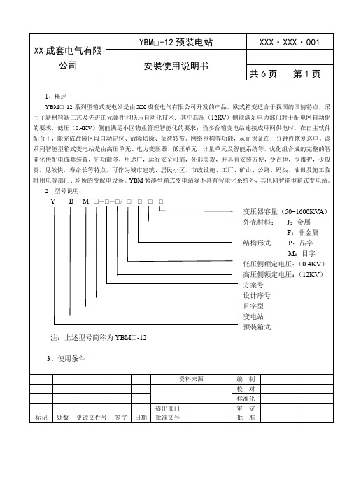
YBM□-12预装电站
XXX·XXX·001
安装使用说明书
共6页
第1页
1、概述
YBM□-12系列型箱式变电站是由XX成套电气有限公司开发的产品,欧式箱变适合于我国的国情特点,采用了新材料新工艺及先进的元器件和低压自动化技术;其中高压(12KV)侧能满足电力部门对于配电网自动化的要求,低压(0.4KV)侧能满足小区物业管理智能化的要求;当多台箱变电站连接成环网供电时,在自主软件配合下,能完成故障区段自动定位、故障切除、负荷转带、网络重构等功能,从而保证在一分钟内恢复送电。该系列智能型箱式变电站是由高压单无、电力变压器、低压单元、计量单元及智能系统等,优化组合成的完整的智能化供配电成套装置,它功能多,用途广,运行安全可靠,外形美观,并具有安装方便,少占地,少维护,少投资,见效快,寿命长等特点,可作为城市建筑、居民小区、市政设施、工厂、矿山、公路、码头、油田及施工临时用电等部门、场所的变配电设备。YBM紧凑型箱式变电站除不具有智能化系统外,其他同智能型箱式变电站。
冲击耐压峰值
(1.2/50µs)
60
75
注:1、()内为干式变压器标准
注:2、此表只适用于正常使用条件,其它使用条件下的耐压值应按相应标准修正。
4.9额定噪声水平
箱式变电站使用说明书
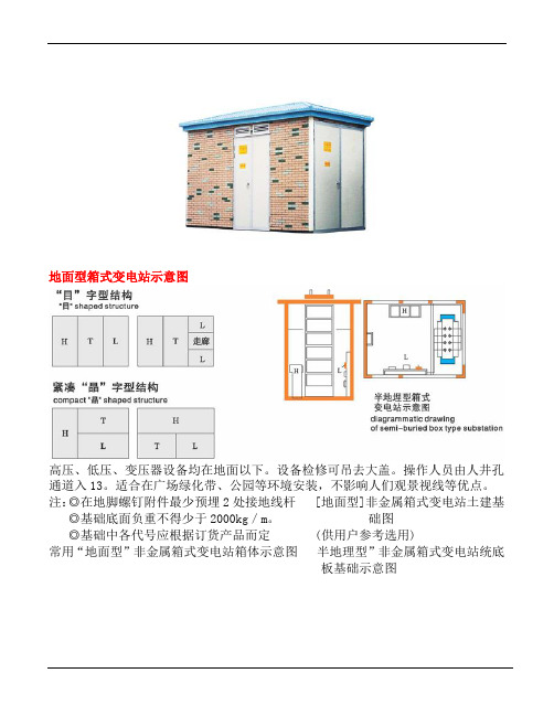
地面型箱式变电站示意图高压、低压、变压器设备均在地面以下。
设备检修可吊去大盖。
操作人员由人井孔通道入13。
适合在广场绿化带、公园等环境安装,不影响人们观景视线等优点。
注:◎在地脚螺钉附件最少预埋2处接地线杆 [地面型]非金属箱式变电站土建基◎基础底面负重不得少于2000kg/m。
础图◎基础中各代号应根据订货产品而定 (供用户参考选用)常用“地面型”非金属箱式变电站箱体示意图半地理型”非金属箱式变电站统底板基础示意图高压主电路常用方案低压主电路常用方案箱式变电站,使用安装注意事项◎箱式站基础四周应预埋接地极,变压器和防雷地可合用,其接地电阻R。
◎箱式站起吊应用专用起吊工具,起吊部分必须按箱式站的标明部位。
◎箱式站底部与基础结合处,需用水泥浆抹封,以防水进入电缆室。
◎电缆进入套管后。
其缝隙必须密封,以防虫、水进入。
箱式站投运前必须检查下列箱式站底部与基础结合处必须水平,如遇各门开启有卡住现象,这是因为基础平面不平所至必须调整箱式变电站与基础面结合水平。
调整方法在箱式变电站底部与基础而缝隙处填塞薄铁片直至各室门开户灵活即可。
当整机装配完成后,装车发运必须注意整台箱体应和车前车后有一定距离,防止车在行路中因刹车而前后撞击,同时箱式站底架和车底板必须用电焊焊牢,再用钢丝把底架和车底绞紧,并用绳索从顶盖到车底分几道上下扎紧。
凡绳索扎到之处必须用纸板或其它软物垫好以防涂层表面损伤。
为使运行中箱式站保持完好,最好半年或一年后对内部和外,部进行清扫和擦一次。
如发现因安装或运输中箱体外表面弄脏,可用洗涤剂擦刷,用清水冲洗即可。
典型系统方案举例参考电缆进出,终端供电,高供高计电缆进出,终端供电,高供高计,低压走廊式,低压电容补偿电缆进出,终端供电,高供低计,低压走廊式,低压电容补偿环保型非金属箱式变电站制造:上海昌开电器有限公司。
- 1、下载文档前请自行甄别文档内容的完整性,平台不提供额外的编辑、内容补充、找答案等附加服务。
- 2、"仅部分预览"的文档,不可在线预览部分如存在完整性等问题,可反馈申请退款(可完整预览的文档不适用该条件!)。
- 3、如文档侵犯您的权益,请联系客服反馈,我们会尽快为您处理(人工客服工作时间:9:00-18:30)。
箱式变电站产品Series Compacted Package Sub-station安装使用说明书O peration Manual1.概述GeneralXBJ1系列紧凑型箱式变电站是由天津电气传动设计研究所组织全国百余家企业联合开发的新产品,它吸收了美式箱变、欧式箱变和国产箱变三大派别的优点,采用了新材料新工艺及先进的元器件和高低压自动化技术;其中高压侧能满足电力部门对于配电网自动化的要求,低压侧能满足小区物业管理智能化的要求。
该系列箱式变电站是由高压单元、电力变压器、低压单元、计量单元及智能系统等,优化组合成的完整的智能化供配电成套装置,它功能多,用途广,运行安全可靠,外型美观,并具有安装方便,少占地,少维护,少投资,见效快,寿命长等特点。
可作为城市建筑、居民小区、市政设施、工厂、矿山、公路、码头、油田及施工临时用电等部门、场所的变配电设备。
XBJ1 series intelligent package sub-station is new products developed by Tianjin Electric Transmission Project Institution and other hundreds of companies. The new products combine the advantages of package sub-station from US, European, and China to fit in the situation in our country. New materials, new process and advanced components and automatic technology for high and low voltage are used in the products; the high voltage siding satisfies the requirement of the automation of power supply network from power supply departments and the low voltage siding satisfies the requirement of community intellectualization. XBJ1 series intelligent cabinet transformer station is composed of optimizing the configuration of high voltage components, power transformer, low voltage components, measurement components and intelligent system. It is multifunction and has wide applications. It is able to run reliable and environment friendly. It has beautiful outlooks and id easy to be installed. It has the advantage of taking up less land, les maintenance, less investment, long lifetime. It can be used as power transform and distribution equipment in city construction, communities, city facilities, factories, mines, road construction, harbor, oilfields and can be also used as temporary construction power supply equipment.2.型号说明Symbol ExplanationX B J 1 —37 /0.315M J 1000变压器容量Rated power 1000kVA外壳材料Enclosure materialJ:金属;Metal结构形式P:品字Structure低压侧额定电压: (0.315kV) Secondary Rated Voltage高压侧额定电压: (37kV) Primary Rated Voltage方案号Scheme Number设计序号Design Serial NumberJ:紧凑型Compacted变电站Sub-station箱式Package3. 使用条件:Using Condition3.1 海拔高度:一般不超过2000m.3.2 周围气温:-15℃~+40℃(智能型-5℃~+40℃)(特殊订货条件:严寒气候为-50℃~+40℃;酷热气候为-5℃~+50℃.)3.3 相对湿度:日平均值不大于95%; 月平均值不大于90%.3.4 地震烈度:水平加速不大于0.3g.3.5 无经常性剧烈震动场所.3.6 周围空气应不受腐蚀性或可燃性气体等明显污染.3.7 安装倾斜度不超过3度.3.8 风负荷≤34m/s.3.1 Height above sea level: less than 2000m3.2 Ambient temperature: -15℃~+40℃(for intelligent package sub-station: -5℃~+40℃)(special condition: Cold climate-50℃~+40℃;Hot climate:-5℃~+50℃)3.3Relative humidity:Daily value less than 95%; Average month value less than 90%3.4Earthquake intensity: Level speedup less than 0.3g3.5 No recurrent severe vibration places3.6 Ambient air is not obvious polluted by corrosive or flammable gases.3.7 Installation gradient is less than 3 degrees.3.8 Wind load: ≤34m/s.4. 结构简介Structure本设计考虑到供电用户需求的多样性,在箱变本身结构上,采用模块式结构。
高压开关接入电网型式:终端型。
高、低压设备布置方式:“品”或“目”字型结构。
内装变压器种类:干式变压器。
高压开关选型:陕西同力箱体(外壳)材质:金属外壳。
底架的设计与箱式变电站总体形式和起吊方式相结合,采用了共同底架。
底架材料采用槽钢,工字钢,焊接组合。
底架的两侧有吊装脚,安装脚,金属底架,间隔金属板,壳体等金属部件。
金属门均有良好地线连接,高低压电器设备的金属框架,变压器外壳各部分之间都有可靠连通的接地导体,其最小截面不小于30mm²。
在底架的四周有与接地线相连的端子,供用户在任何方向部位选择接地点。
变压器内装排风装置,以适应用户要求,变压器室两侧装有门,便于变压器安装及检修,门内还装有安全隔离门,防止人员误入带电间隔区,保证设备及人身安全。
Taking g into account diversity of users’ requirements, the structure of the main body of the sub-station is kind of modular structure. One sub-station may be composed by following patterns.Divide by HV switch into the grid: terminal typeDivided by HV& LV equipment layout:“品”or “目”font structureDivided by transformer inside: Dry transformerDivided by HV switch: SHANXITONGLI。
Divided by equipped with intelligent system: impacted XBJ1Material of enclosure: metalDesigning of bottom frame composes with the whole form of the package sub-station and lifting method and adopting the same bottom flame. Bottom flame is welded by channel, I-beam. The sides of the bottom flame are composed of hoisting legs, feet installed, metal chassis, spacing metal plates shell etc.. metal doors connect with ground well. The minimum area of Earthling conductor to connect the metal flame of H.V & L.V equipment and enclosure is 30mm². The terminals under the bottom flame are connecting with earth-line, so customers could choose the connect point randomly.The transformer room is furnished automatic ventilation equipment. There are doors on both sides of the enclosure to install and maintain. Safety insulted doors are installed inside the door. Chain alarm equipment is equipped on door to prevent that workers go into the working area to protect device and workers.5.安装、使用及注意事项Installation, operating and maintenance 箱变按要求运输抵达目的地后,用户对其包装及外表是否完整无损进行检查,并履行交接手续。