注CO2煤层气采收率技术
二氧化碳地质埋存提高煤层气采收率的数值新方法
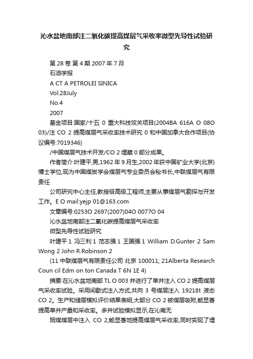
CO 2sequestration in coals and enhanced coalbed methane recovery:New numerical approachXiaorong Wei a,*,Paul Massarotto a ,Geoff Wang a ,Victor Rudolph a ,Sue D.Golding ba Division of Chemical Engineering,The University of Queensland,Brisbane,QLD 4072,Australia bDivision of Earth Sciences,The University of Queensland,Brisbane,QLD 4072,Australiaa r t i c l e i n f o Article history:Received 14October 2008Received in revised form 21January 2010Accepted 21January 2010Available online 4February 2010Keywords:Coalbed methane CO 2sequestration Mixed gases injection Simulationa b s t r a c tMixed gases injection into a large coal sample for CO 2sequestration in coals and enhanced coalbed meth-ane recovery was investigated using a new numerical approach.A dynamic multi-component transport (DMCT)model was applied to simulate ternary gas (CH 4–CO 2–N 2)diffusion and flow behaviors for better understanding and prediction of gas injection enhanced coalbed methane (ECBM)recovery processes.Several cases were designed to analyze the effects of injection gas composition and pressure on gas dis-placement dynamics in a large coal sample.The calculated results suggest that mixed gas injections have similar profiles of methane recovery as pure N 2injection,and mixtures of N 2and CO 2reduce the ultimate methane recovery compared to pure CO 2.The breakthrough time of pure CO 2injection is longer than mixed gas injections.Injection gas composition has significant effect on produced gas composition.Crown Copyright Ó2010Published by Elsevier Ltd.All rights reserved.1.IntroductionGas injection into coalbeds for carbon dioxide geo-sequestra-tion and coalbed methane recovery has recently attracted growing attention due to increasing concerns about greenhouse gases and the emerging commercial significance of coalbed methane produc-tion all over the world.There are three principal types of ECBM recovery processes,namely N 2,CO 2and flue gas (or mixed gases CO 2–N 2)injections for ECBM recovery.Field tests [1]suggested that CO 2-ECBM operation can produce more methane recovery than N 2-ECBM.However,the high cost of separating CO 2from flue gas is the main problem affecting implementation of CO 2-ECBM recovery.Mixed injection to enhance coalbed methane recovery may avoid the high preparation cost and improve methane produc-tivity.Therefore,it is necessary to study the effects of injection gas composition and pressure on gas displacement dynamics in order to optimize the mixed gases injection enhanced methane recovery.A very good review on enhanced coalbed methane recovery by injecting CO 2,N 2or gas mixtures have been made by Mazzotti et al.[2].So far most of previous studies on this area are focused on investigation of single or binary gas adsorption and diffusion in coals,which associate with CO 2/N 2-ECBM recovery processes.A limited amount of experimental studies have been made on sorp-tion of flue gas (or ternary gas CH 4–CO 2–N 2)on coal.Mazumder et al.[3]studied industrial flue gas sorption capacities on largedry and wet Silesia coal sample at 353K and medium to high pres-sure (5–11MPa).Stevenson et al.[4]examined adsorption of ter-nary gas mixtures on dry Australian coal at 303.15K and pressure up to 5.2MPa.Several Japanese researchers [5,6]investi-gated CH 4–CO 2–N 2ternary gas adsorption on powdered coal sam-ples at 308K and pressures of 3and 6MPa.Ottiger et al.[7]measured and simulated the pure,binary and ternary adsorption of these gases on a dry and powdered coal sample at pressure up to 18MPa and temperatures of 318K and 343K.Very few works have been conducted on ternary gas CH 4–CO 2–N 2diffusion and flow dynamics for flue gas-ECBM recovery.Reznik et al.[8]carried out a set of displacement experiments to analyze the effect of CO 2–N 2mixture injection on the recovery of in-situ methane from a large bituminous coal sample at injection pressure of 5.516MPa and temperature between 288and 293K.Two re-cently published papers [9,10]reports the laboratory experiments and simulations of mixed gas injection enhanced coalbed methane recovery at mid or high pressures.Mazumder et al.performed core flooding experiments with CO 2/N 2/flue gas injection into a large coal sample at high temperature of 318K and injection pressure up to 9MPa (supercritical condition).Jessen et al.measured and simulated binary and ternary gas diffusion and flow in meshed coal samples at 295K and 4.14MPa.In late 1999,The Alberta Research Council performed a single well micro-pilot test of injecting flue gas into coalbed reservoirs in Alberta [1].Although the aforementioned studies provide some valuable re-sults,the following issues need to be addressed in the simulation investigation of mixed gas-injection ECBM processes.0016-2361/$-see front matter Crown Copyright Ó2010Published by Elsevier Ltd.All rights reserved.doi:10.1016/j.fuel.2010.01.024*Corresponding author.Tel.:+61(0)733468735;fax:+61(0)733654199.E-mail address:x.wei@.au (X.Wei).Fuel 89(2010)1110–1118Contents lists available at ScienceDirectFueljournal homepage:www.else v i e r.c o m /l o c a t e /f u el(1)Multi-porosity system of coals.One of main technical chal-lenges is to measure and model the wide range of the pore spaces typically occurring in ing large coal samples in laboratory experiments is a key to retain heterogeneity of pore structure[9].(2)Multi-component gas sorption and diffusion processes.Onesignificant deficiency in current CBM models is that most models are based on a single-component unipore diffusion formulation[11].These models are not suitable to simulate the multi-component gas counter-diffusion andflow behaviors.(3)Stressed sorption and constant volume boundary condition.The current experimental approach to deriving sorption iso-therm is to subject coal samples to increasing sorbentfluid pressures with no external stresses placed upon the sample.This method of derivation is non representative of the coal in situ where,initially,anisotropic triaxial stresses are pres-ent upon the sample.Coal is also contained in a constant vol-ume environment and therefore during sorption the resultant effective stress would vary dynamically.The aims of this work are to address these needs by using a new DMCT model and to evaluate the effects of injection gas composi-tion and injection pressure on mixed gases displacement kinetics in a large coal sample,i.e.methane recovery,breakthrough times of CO2,N2,coal permeability.The DMCT model has been validated to simulate CH4–CO2diffusion andflow by comparing with the experimental data obtained from UQ lab tests.The details refer to our previously published paper on AIChE Journal[12].This paper presents a further study based on the results of CO2displacement tests.The DMCT model was applied to simulate ternary gas CH4–CO2–N2diffusion andflow dynamics,which provides valuable information for optimizing the process of CO2sequestration and enhanced methane recovery.2.Numerical modelA dynamic multi-component transport(DMCT)model[12,13] was developed to deal with multi-component gas counter-diffu-sion andflow in the coal matrix.Fig.1shows the conceptual mod-el.The coal matrix is treated as a cylindrical cell surrounded by main fractures.It contains particles with uniform radius,between which are open micro-fractures.The pore structure within parti-cles adopts the assumptions of Ruckenstein model[14].The parti-cles have bimodal pore structure,containing uniform radius microporous micro-particles with the space between micro-parti-cles making up the meso-/macro-porosity.Gasflow through open micro-fractures is simplified to be1D gasflow obeying Darcy’s law, and water phase is not included in the model.Gas diffusion in the coal matrix is assumed to be bidisperse pore diffusion:surface dif-fusion in micropores and bulk or Knudsen diffusion in meso/mac-ropores.This study is to simulate the displacement kinetics of coal gases for ECBM recovery,rather than a special investigation of pore structure in coals.Therefore,the micropore size distribution is ignored and the micropore size within a coal sample is assumed to be homogeneous.To simplify the calculations,the equilibrium between the gas phase and adsorbed phase is assumed to be instant.Nomenclature[B m]matrix of inverted Maxwell–Stefan macropore diffusiv-ities(s/m2)[B l]matrix of inverted Maxwell–Stefan micropore diffusivi-ties(s/m2)C ci molar concentration of gas component i in open micro-fractures(mol/m3)C mi molar concentration of gas component i in macropores(mol/m3)C mi0initial gas molar concentration of component i in mac-ropores(mol/m3)C t total concentration(mol/m3)C l i molar concentration of component i in micropores(mol/m3)C l i0initial molar concentration of component i in microp-ores(mol/m3)c f cleat-volume compressibility(1/Pa)c m matrix shrinkage compressibility due to methanedesorption(1/Pa)c ki differential swelling coefficients of component iD em0initial effective macropore diffusivity(m2/s)D e l0initial effective micropore diffusivity(m2/s)D miM Knudsen diffusivity of component i(m2/s)D mij molecular diffusivity of binary pair iÀj(m2/s)D iV Maxwell–Stefan micropore diffusivity of component i(m2/s)D ij Maxwell–Stefan micropore counter diffusivity betweencomponents i and j(m2/s)E Young’s modulus(Pa)f i partial fugacity of component i in gas phase(Pa)I l i adsorption isothermJ m-c;i mass exchange rate between cleats and bulk coal per unit volume of coals(mol/(m2s))J m-l;i mass exchange rate between micropores and macrop-ores(mol/(m2s))k,k0fracture permeability and Initial fracture permeability, respectively(mD)½L m matrix of macropore diffusivities(m2/s)½L l matrix of micropore diffusivity(m2/s)½N m matrix of molarfluxes in particles(mol/(m2s))½N l matrix of molarfluxes in micro-particles(mol/(m2s)) nc number of components in the systemp pressure(Pa)P Li Langmuir pressure of component i(Pa)R particle radial coordinate(m)R m radius of particle(m)r micro-particle radial coordinate(m)r l radius of micro-particle(m)u g velocity of gas phase(m/s)V Lj Langmuir volume of component j(mol/m3)y i mole fraction of component i in gas phaseGreek lettersa sj matrix shrinkage/swelling coefficient of component j c ratio of diffusion rates in the micropores to that in themacropores[C]matrix of thermodynamic factorse c,e c0fracture porosity and initial fracture porosity,respec-tivelye m,e l Macro-porosity and micro-porosity,respectivelyh i fractional surface occupancy of species im Poisson ratior effective horizontal stress(Pa)s m,s l macropore and micropore tortuosity,respectivelyuifugacity coefficient of component i in gas phaseX.Wei et al./Fuel89(2010)1110–111811112.1.Gas diffusion and flowWith the above assumptions,three levels of mass balance equa-tions can be developed for the three levels of pore sizes i.e.open micro-fractures,meso/macropores and micropores,respectively.The mass balance equations for gas flow in the micro-fractures can be simplified as 1-dimensional Darcy flow,givinge c@ðC ci Þ@t À@ðC ci u g Þ@xþJ m -c ;i ¼0ði ¼1;2;...;nc Þð1Þwhere C ci is the gas concentration in fractures of the gas compo-nent i ;nc is the number of components;u g is gas velocity depend-ing on permeability and pressure gradient along the coal matrix cell;e c is fracture porosity;and J m-c,i is the mass exchange rate be-tween fractures and particles per unit volume of bulk coal.Multi-component gas diffusion in meso/macropores within a particle can be described bye m@ðC mi Þ@t ¼À1R 2@@RðR 2N m ;i ÞÀJ m Àl ;iði ¼1;2;...;nc Þð2Þwith initial and boundary conditionst ¼0:C mi ¼C mi 0ð3ÞR ¼0:@C mi@R¼0;R ¼R m :C mi ¼C cið4Þwhere e m is macro-porosity;N m,i is pore diffusion flux in the parti-cle;and J m-l ,i is mass exchange rate between micropores and meso/macropores.The pore diffusion flux is defined as½N m ¼À½B e mÀ1@½C m @R ¼À½L m @½C m@Rð5Þwhere [L m ]is the macropore diffusivity matrix and defined by theinverted matrix of inverted MS effective diffusivity B e m ÂÃ.The B e m ÂÃconsists of the following elements [15]:B e m ði ;j Þ¼1emiM þP nc k ¼1k –iy k e mikði ¼j ;i ¼1;2;...;nc ÞÀy ie mijði –j ;i ¼1;2;...;nc Þ8>><>>:ð6Þwhere D e miM is effective Knudsen diffusivity of component i ;y i is mo-lar fraction of component i ;and D e mij is effective binary molecular diffusivity between species i and j .Gas diffusion in micropores within a micro-particle can be de-scribed bye l@C l i @t¼À1r 2@@r r 2N l ;i ÀÁði ¼1;2;...;nc Þð7Þwith initial and boundary conditionst ¼0:C l i ¼C l i 0ðr <r l Þð8Þr ¼0:@C l i@r¼0ði ¼1;2;...;nc Þð9Þr ¼r l :C l i ¼I l i ðP Þði ¼1;2;...;nc Þð10Þwhere I l i (P )is the adsorption equilibrium which can be estimated by a sorption isotherm model;e l is the micro-porosity;N l ,i is the surface diffusion flux in the micro-particle.According to the Max-well–Stefan theory,micropore diffusion flux can be represented as½N l ¼À½B l À1½C@½C l @r ¼À½L l @½C l@rð11ÞThe matrix of inverted MS micropore diffusivities [B l ]has theelementsB l ði ;j Þ¼1Ds iVþP nc k ¼1k –ih k D s ikði ¼j ;i ¼1;2;...;nc ÞÀh i D sijði –j ;i ¼1;2;...;nc Þ8>>><>>>:ð12Þwhere h i is fractional surface coverage;[C ]is matrix of thermody-namic factors;D s iV and D sij are MS micropore diffusivity of compo-nent i and MS counter diffusivity between components i and j ,respectively.2.2.Coal shrinkage and swellingThe values of fracture porosity and permeability may vary in course of gas injection/production due to coal matrix shrinkage and swelling.To evaluate the variations of these parameters under a condition of the stressed sorption,the Shi-Durucan (SD)model [16,17]was utilized to simulate the stress-dependent permeability and porosity for multi-component system.In this model,the change in effective horizontal stress is given byr Àr 0¼Àm1Àmðp Àp 0ÞþE3ð1Àm ÞX n j ¼1a sj ðC l j ÀC l j 0Þð13Þwhere r is effective horizontal stress;m is Poisson ratio;E is Young’s modulus;a sj is matrix shrinkage/swelling coefficient of component j ;p is the pore ing the extended Langmuir isotherm,the adsorbed volume for gas component j may be approximated byC l j ¼V Lj py j b j1þp P n j ¼1y j b jð14Þwhere V Lj is Langmuir volume of component j ;y j is the molarfraction of component j in gas phase;b j is Langmuir constant of1112X.Wei et al./Fuel 89(2010)1110–1118component j.The fracture porosity e c varies exponentially with change in the effective horizontal stresse c¼e c0eÀc fðrÀr0Þð15Þwhere e c0is initial fracture porosity;cf is cleat-volume compress-ibility.The fracture permeability can be derived from the following relationship:k k0¼e ce c03ð16Þwhere k and k0are fracture permeability and initial fracture perme-ability,respectively.2.3.Gas sorption equilibriumThe multi-component sorption equilibria were determined using ideal adsorbed solution-real gas(IAS-RG)approach with Langmuir isotherm[18]in this study.It is assumed that the ad-sorbed phase behaves like an ideal solution or activity coefficients of all components in the adsorbed phase are equal to unity for all values of pressure,temperature and composition.With this assumption,the thermodynamic equilibrium relation can be approximated by[19].f i¼f0ix ið17Þwhere f i is partial fugacity of component i in gas phase,f0iis fugacity of pure component i in gas phase at standard state,and x i is mole fraction of component i in adsorbed phase.The Eqs.(3)–(5)can be rewritten in terms of fugacity coefficient[18]pyi ui¼p0iu0ix ið18Þwhere p0iis standard state pressure of pure component i in the ad-sorbed phase,u i is fugacity coefficient of component i in gas phase, and y i is mole fraction of component i in gas phase.The fugacity coef-ficients were estimated using Peng–Robinson equation of state[20].The total adsorption amount and partial adsorption amount can be estimated by1 C t ¼X nci¼1x iC lið19Þwhere C t is total adsorption amount,C0liis adsorption amount of pure component i at standard state.A loose coupling algorithm[21]is adopted in this work for numerically solving the highly coupled model equations.Our case is a coupled system dealing with different processes,i.e.gas sorp-tion equilibrium,gas diffusion and Darcianflow,and matrix shrinkage and swelling.Among these processes,the gas diffusion andflow are central,which is described by Eqs.(1),(2),and(7). These equations will be discretized and solved independently and then coupled with the sorption equilibrium of the gases and matrix shrinkage/swelling behavior.3.Case designA series of CO2displacement tests have been conducted in the University of Queensland’s laboratory.Currently we only tested binary gas diffusion andflow in the coal sample at low pressures of0.4MPa and2.0MPa.The experiments and simulations of these experiments were presented in our previously published paper [12].Based on the simulation results of these experiments,a series of ternary gas diffusion andflow simulations were performed un-der a range of injection gas compositions and injection pressures.It is assumed that the cases are performed under the same con-ditions as the CO2displacement test conditions,and the injection is operated at a constant injection pressure and at a constant injec-tion composition.In these calculations,mobile liquid is not consid-ered.Mixtures of CO2and N2are used to represent injection gases, and all three gases(CH4,CO2and N2)access same pores.Several cases were designed to analyze the effects of injection gas compo-sition and pressure on the gases diffusion andflow behaviors.Five injection compositions were considered containing0%,25%,50%, 75%,and100%mole fraction of CO2,with the remainder N2,named as Case1–5,respectively.Each case is simulated at two injection pressures,i.e.0.4MPa and2.0MPa.The designed cases are shown in Table1.To numerically model multi-component gas diffusion andflow in a large coal sample using the DMCT model,two types of param-eters need to be defined in the simulation:(1)coal properties,i.e. porosity,tortuosity and mechanical properties;(2)Gas properties, i.e.thermodynamic properties,kinetic parameters for meso-/mac-ropore or micropore diffusions.3.1.Coal propertiesTable2shows the values of coal properties used in the simula-tions.Three types of porosities are defined in the model to describe the multi-scale porosity system:fracture porosity(e c),macro-porosity(e m)and micro-porosity(e l).The relative values of these porosities were taken from experimental data on same type of coal [22–24].Although literature data may not exactly match our coal,a sensitivity analysis was carried out to understand how changing porosity allocations affects the outcome[12].The macropore and micropore tortuosities were obtained through sensitivity analysis as well.Since the focus of this study is on simulating the displace-ment kinetics of gases for ECBM recovery,rather than a special Table1Cases designed to analyzing gas composition effects.Cases Injection gas Injection pressure(MPa) Case1CO2(0%),N2(100%)0.4,2.0Case2CO2(25%),N2(75%)0.4,2.0Case3CO2(50%),N2(50%)0.4,2.0Case4CO2(75%),N2(25%)0.4,2.0Case5CO2(100%),N2(0%)0.4,2.0Table2Values of coal properties used in the model simulations.Parameters Values NoteMoisture(%) 5.00These values weredetermined byexperiments.Helium Density(kg/m3)1285.00Total porosity(%)11.22Vitrinite random reflectance(Vro)0.97–1.06Face cleat spacing(m)0.007Butt cleat spacing(m)0.008–0.01Compressibility(PaÀ1)0.137(0.4MPa),0.125(2.0MPa)Young’s modulus(Â106Pa)0.3Â106Cleat porosity(>50Â10À9m,%) 1.2These values wereestimated according toprevious researchresults for same coaltype and rank(highvolatile bituminouscoal).Mesoporosity(2–50Â10À9m,%) 4.0Micro-porosity(<2Â10À9m,%) 6.0Poisson’s ratio0.38Macropore and microporetortuosity1.5These values weredetermined byfittingmodel results withexperimental data.Coal shrinkage/swellingcoefficient of CH4(Â10À3)1.105(0.4MPa),0.257(2.0MPa)Coal shrinkage/swellingcoefficient of CO2(Â10À3)0.338(0.4MPa),0.136(2.0MPa)X.Wei et al./Fuel89(2010)1110–11181113investigation of pore structure in a specific coal,the allocated val-ues of sub-porosities and tortuosities are considered reasonable as input data.The mechanical parameters,i.e.coal compressibility and Young’s modulus,were estimated based on the CO2displacement tests.The coal matrix shrinkage/swelling coefficients used in Shi and Durucan model were predicted by matching the model results with CO2displacement tests.The values of these parameters are also listed in Table2.3.2.Gas propertiesThe thermodynamic properties of gas components CH4,CO2and N2are summarized in Table3.To use the MS diffusion Eqs.(5)and (6)in modelling gas diffusion through the bulk phase,the binary molecular diffusivities between different species were estimated using the Fuller–Schettler–Giddings correlation[25].Knudsen dif-fusivities of each species were approximated by the analytical for-mula presented by Jackson[26].The combined Knudsen andmolecular diffusivity is calculated using the Bosanquet approxima-tion[26].The values of kinetic parameters calculated for the ternary gas system are summarized in Table4.The Knudsen diffusivities of three species decrease in the order of CH4>N2>CO2,and the meso-/macropore diffusivities decrease with increasing pressure. The MS micropore diffusivity adopted the simulation results of CO2displacement tests,which is around8Â10À10m2/s.4.Model results and discussion4.1.Methane recoveryFig.2shows the calculated CH4recovery for all cases under the condition of injection pressure of0.4MPa,respectively.It can be seen from thefigure that all mixed gas injections are able to achieve100%methane recovery and they have the similar profiles of methane recovery.The100%of methane recovery is defined here as the negligible methane content in produced gas.However,a maximum difference of15%is found between the mixture with N2of25%and75%that occurred at around15min after gas injec-tion.The N2-enriched injection gas yields a relatively slow desorp-tion of methane from the coal,and thus a lower methane recovery (before60min),while the CO2-enriched injection gas gives a fast methane desorption and a higher methane recovery(also before 60min).Therefore,the mixtures of N2and CO2reduce the methane recovery,which is consistent with the experimental results ob-tained by Reznik et al.The methane recovery profiles from the mixed gas injections are all similar to the profile for pure N2injection,especially the mixture with N2of75%.This suggested that N2,regardless of its concentration in the mixture,is the governing component that controls the methane recovery.The initial methane recovery by pure CO2injection is lower than the mixed gas injections and pure N2injection,while methane desorption by CO2injection increases very fast and is in the lead after about2min of gas injection.The reason for this phenomenon is the higher capacity of CO2adsorp-tion on coal surface than that of CH4.The loss of injected CO2vol-ume is greater than the volume of the CH4released from the coal surface.Therefore,it would take a longer time to inject enough amount of CO2to replace methane at the initial time.After that, the methane desorption by CO2injection is larger than the amounts by mixed gas and N2injections,and thus the methane recovery profile from the mixture injections lie between the recov-ery lines of pure N2injection and pure CO2injection.020*********Time (mins)Pure=0.25:0.75=0.50:0.50=0.75:0.25PureN2CO2:N2CO2:N2CO2:N2CO2Effects of injection gas composition on methane recovery at pressureTable3Thermodynamic properties of gas components used for calculations.Component Critical pressure(atm)Critical temperature(K)Critical volume(cm3/mol)Critical compressibilityfactorAcentricfactorLangmuirvolume(cc/g)Langmuirpressure(atm)CH444.52190.699.00.2880.00824.020.00 CO271.42304.193.90.2740.22535.0 6.67 N232.80126.289.80.2900.049.8618.14Table4Knudsen,Molecular and macropore diffusivities used in simulation.Pressure(MPa)Species Knudsen diffusivity(Â10À6m2/s)Molecular diffusivity(Â10-6m2/s)Macropore diffusivity(Â10À6m2/s)0.4CH4 4.00– 2.140.4CO2 2.57– 1.500.4N2 3.16– 1.360.4CH4–CO2–26.60–0.4CH4–N2– 5.58–0.4CO2–N2– 4.20–2.0CH4 4.00–0.752.0CO2 2.57–0.572.0N23.16–0.422.0CH4–CO2– 5.32–2.0CH4–N2– 1.12–2.0CO2–N2–0.84–1114X.Wei et al./Fuel89(2010)1110–1118The effects of injection gas pressure on methane recovery for mixed gas injections are shown in Fig.3.It can be seen from the fig-ure that the mixed gas injections are able to achieve nearly 100%methane recovery in spite of injection gas pressure.However,it takes a longer time for high injection pressure (2.0MPa)to achieve as much as low injection pressure (0.4MPa)because the initially adsorbed volume of methane is higher for high gas pressure.The mixed gas injections with injection pressure of 2.0MPa have sim-ilar profiles of methane recovery as injection pressure of 0.4MPa.The N 2-enriched injection gas yields a relatively slow desorption of methane from the coal,and thus a lower methane recovery (be-fore 600min),while the CO 2-enriched injection gas gives a fast methane desorption and a higher methane recovery (also before 600min),as indicated in Fig.3.4.2.Mole fraction of methane in produced gasFig.4illustrates the calculated mole fraction of CH 4in produced gas for all cases at injection pressure of 0.4MPa.When the CO 2gas is injected into the coal sample,it is rapidly adsorbed by the coal so that only a small amount of CO 2can remain in the free phase.Therefore,the breakthrough time of pure CO 2injection is longer than other cases.Here,the breakthrough time is defined as the time when the mole fraction of injected gas in produced gas is up to 1%.In the case of pure CO 2injection,the concentration of CH 4de-creases sharply after CO 2breakthrough in produced gas because methane desorption is faster than other cases.Moreover,the injec-tions are assumed to be operated at a constant injection pressure,which yields higher injection rates for pure CO 2injection.There-fore,the mole fraction of CO 2in produced gas decrease faster than other cases.The breakthrough times of mixed gas injections are equal to the breakthrough time of pure N 2injection.Since the methane desorption rates of mixed gas injections decrease in the order of the mixture with N 2of 25%>50%>75%,the methane mole fraction in produced gas for the injection gas with 25%N 2is highest among the three cases until the model runs about 10min,and then it decreases faster than other cases.The effects of injection gas pressure on methane mole fraction in produced gas for mixed gas injections are shown in Fig.5.It can be seen from the figure that the profiles of methane mole frac-tion in produced gas on the condition of injection pressure of 2.0MPa are similar to those when the injection pressure is 0.4MPa.However,it takes about 10times longer for the mixed gas injections under the injection pressure of 2.0MPa to reduce mole fraction of methane in produced gas to about 1%than the mixed gas injections under injection pressure of 0.4MPa.This is obviously because the methane adsorption amount on coal surface at high system pressure is much more than that at low pressure.4.3.N 2adsorptionFig.6shows the calculated amounts of N 2adsorption on coal for pure N 2injection and mixed gas injections for all cases under the condition of injection pressure of 0.4MPa.The DMCT model results show that only a very small amount of the nitrogen is adsorbed by the coal when CO 2(625%)is present in the injection gases.The predicted results are consistent with the experimental results that100200300400500600700Time (mins)=0.25:0.75 =0.50:0.50 =0.75:0.250.4MPa2.0MPaCO 2:N 2CO 2:N 2CO 2:N 2Fig.3.Effects of injection gas pressure on methane recovery.20406080100Time (mins)Pure =0.25:0.75 =0.50:0.50 =0.75:0.25Pure N 2CO 2:N 2CO 2CO 2:N 2CO 2:N 2Effects of injection gas composition on methane mole fraction in produced pressure of 0.4MPa.100200300400500600700Time (mins)=0.25:0.75 =0.50:0.50 =0.75:0.250.4MPa2.0MPaCO 2:N 2CO 2:N 2CO 2:N 2Effects of injection gas pressure on methane mole fraction in produced 0.0020406080100Time (mins)Pure N2CO2:N2=0.25:0.75CO2:N2=0.50:0.50CO2:N2=0.75:0.25X.Wei et al./Fuel 89(2010)1110–11181115。
注二氧化碳提高煤层气采收率数值模拟

注二氧化碳提高煤层气采收率数值模拟
赵金;张遂安;马东民;湛凤巍;叶姜;安腾飞;张维驿
【期刊名称】《天然气与石油》
【年(卷),期】2012(30)1
【摘要】随着全球温室效应的逐渐增强,CO2的处理已成为各国关注的问题.在煤层气开采中,利用CO2提高煤层气采收率也成为研究热点.针对煤层气开发过程中的产气量低的问题,从物理模拟方法和数值模拟角度出发,进行了CO2置换煤层气的等温吸附实验以及置换过程中的浓度测定研究,并对山西晋城地区运用ECLIPSE 软件进行了数值模拟研究.研究结果表明,CO2能提高煤层气的产量和采收率,使产量保持稳定,采收率高达94%,同时也能有效地减少CO2的排放,缓解温室效应.【总页数】4页(P67-70)
【作者】赵金;张遂安;马东民;湛凤巍;叶姜;安腾飞;张维驿
【作者单位】中国石油大学(北京)气体能源开发与利用教育部工程研究中心,北京102249;中国石油大学(北京)气体能源开发与利用教育部工程研究中心,北京102249;西安科技大学地质与环境学院,陕西西安710054;中国石油大学(北京)气体能源开发与利用教育部工程研究中心,北京102249;中国石油大学(北京)气体能源开发与利用教育部工程研究中心,北京102249;中国石油大学(北京)气体能源开发与利用教育部工程研究中心,北京102249;中国地质大学(北京)能源学院,北京100083【正文语种】中文
【相关文献】
1.注气驱替提高煤层气采收率实验研究
2.注二氧化碳和氮气提高煤层气采收率的经济评价及敏感性分析
3.注二氧化碳提高煤层气采收率实验系统设计
4.煤层气井组生产后期注 CO 2提高采收率研究磁
5.沁水盆地南部注二氧化碳提高煤层气采收率微型先导性试验研究
因版权原因,仅展示原文概要,查看原文内容请购买。
阐述二氧化碳驱提高采收率技术及应用

阐述二氧化碳驱提高采收率技术及应用提高采收率(EOR)研究是油气田开发永恒的主题之一。
将二氧化碳注入衰竭的油层,可提高油气田采收率,己成为世界许多国家石油开采业的共识。
二氧化碳驱一般可提高原油采收率7%~15%,延长油井生产寿命15~20a。
二氧化碳来源可从工业设施如发电厂、化肥厂、水泥厂、化工厂、炼油厂、天然气加工厂等排放物中回收,既可实现使气候变暖的温室气体的减排,又可达到增产油气的目的。
1、二氧化碳驱油机理1.1降粘作用二氧化碳与原油有很好的互溶性,随着溶解气油比的增加,原油粘度显著降低,粘度降低后原油流动能力增大,油水流度比减小,提高原油产量。
1.2膨胀作用二氧化碳注入油藏后,使原油体积大幅度膨胀,便可以增加地层的弹性能量,还有利于膨胀后的剩余油脱离地层水以及岩石表面的束缚,变成可动油,是驱油效率升高,提高原油采收率。
1.3萃取和汽化原油中的轻烃在一定压力下,二氧化碳混合物能萃取和汽化原油中不同组分的轻质烃,降低原油相对密度,从而提高采收率。
二氧化碳首先萃取和汽化原油中的轻质烃,随后较重质烃被汽化产出,最后达到稳定。
1.4溶解气驱作用大量的二氧化碳溶于原油中具有溶解气驱的作用。
降压采油机理与溶解气驱相似,随着压力下降,二氧化碳从液体中逸出,液体内产生气体驱动力,提高了驱油效果。
另外,一些二氧化碳驱油后,占据了一定的孔隙空间,成为束缚气,也可使原油增产。
1.5提高渗透率作用二氧化碳溶于原油和水,使其碳酸化。
碳酸水与油藏的碳酸盐反应,生成碳酸氢盐。
碳酸氢盐易溶于水,导致碳酸盐尤其是井筒周围的大量水和二氧化碳通过的碳酸岩渗透率提高,使地层渗透率得以改善,上述作用可使砂岩渗透率提高5%-15%,同时二氧化碳还有利于抑制粘土膨胀。
另外,二氧化碳-水混合物由于酸化作用可以在一定程度上解出无机垢堵塞、疏通油流通道、恢复单井产能。
2、二氧化碳驱种类及注入工艺2.1二氧化碳驱的种类(1)二氧化碳混相驱。
混相驱油是在地层高退条件下,油中的轻质烃类分子被二氧化碳提取到气相中来,形成富含烃类的气相和溶解了二氧化碳的原油的液相两种状态。
二氧化碳增加煤层气采收率技术
二氧化碳增加煤层气采收率技术下载提示:该文档是本店铺精心编制而成的,希望大家下载后,能够帮助大家解决实际问题。
文档下载后可定制修改,请根据实际需要进行调整和使用,谢谢!并且本店铺为大家提供各种类型的实用资料,如教育随笔、日记赏析、句子摘抄、古诗大全、经典美文、话题作文、工作总结、词语解析、文案摘录、其他资料等等,想了解不同资料格式和写法,敬请关注!Download tips: This document is carefully compiled by this editor. I hope that after you download it, it can help you solve practical problems. The document can be customized and modified after downloading, please adjust and use it according to actual needs, thank you!In addition, this shop provides you with various types of practical materials, such as educational essays, diary appreciation, sentence excerpts, ancient poems, classic articles, topic composition, work summary, word parsing, copy excerpts, other materials and so on, want to know different data formats and writing methods, please pay attention!引言随着全球能源需求的增长和环境保护意识的提高,煤层气作为一种清洁能源备受关注。
中国油气田注CO2提高采收率实践罗二辉1胡永乐1李保柱
中国油气田注CO2提高采收率实践罗二辉1,胡永乐1,李保柱1,朱卫平2(1.中油勘探开发研究院,北京 100083;2. 中油吐哈油田分公司,新疆哈密 839009)摘要:在调研大量相关文献的基础上,详细综述了中国油气田50多年的注CO2提高采收率实践。
首先依据中国各大油区公开发表的文献实验数据,从室内机理实验统计CO2驱油关键技术参数,对比分析原始地层压力与最小混相压力。
其次,根据不同储层类型,总结了国内在低渗透油藏、高含水油田、复杂断块、稠油油藏、碳酸盐岩油藏及煤层气等储集层开展的注CO2矿场项目。
现场试验结果显示,提高采收率幅度为1.07%~6.00%,换油率为0.98~2.49t/t。
最后结合矿场已有经验及存在问题,提出CO2驱油技术攻关方向。
关键词:注CO2;最小混相压力;混相驱;提高采收率;换油率中图分类号:TE357.7 文献标识码:A引言美国注CO2采油已有50多年的历史,最初只是为了提高原油采收率,近年来随着CO2温室效应导致的气候变化,地质埋存被作为温室气体减排的一种有效手段受到环保人士和油气工作者的高度关注。
中国政府在2009年联合国气候大会上承诺,到2020年中国单位国内生产总值CO2排放比2005年下降40%~45%,减排目标将作为约束性指标纳入国民经济和社会发展的中长期规划,保证承诺的执行受到法律和舆论的监督[1]。
研究CO2驱油与埋存这一双赢技术凸显重要,中国在注CO2驱油机理实验和矿场先导试验方面的研究一直没有停止过,1965年首先在大庆油田开展了注二氧化碳水小规模的先导性试验,提高采收率7.8%。
1986年谢尚贤针对大庆油田早期开发的萨、喇、杏油田已进入中高含水期阶段这一情况,论证了CO2非混相驱油的可行性和技术界限[2]。
2006年国家科技部批准“973”计划“温室气体提高石油采收率的资源化利用及地下埋存”,CO2提高采收率及地下埋存研究进入崭新阶段[3]。
“十一五”末吉林油田建成了中国第1个含CO2天然气藏开发及CO2驱油与埋存一体化系统,目前,正在进行年产油50×104t规模的CO2驱项目工业化推广,预计提高采收率13.8%,该项目是中国第1个CO2驱工业化推广项目,将具有显著的经济和社会效益[4]。
沁水盆地深煤层注入CO2提高煤层气采收率可行性分析
沁水盆地深煤层注入CO2提高煤层气采收率可行性分析申建;秦勇;张春杰;胡秋嘉;陈伟【期刊名称】《煤炭学报》【年(卷),期】2016(041)001【摘要】探讨CO2注入深煤层提高煤层气采收率可行性对于解放我国丰富深部煤层气资源具有积极意义.分析了沁水盆地不同深度条件下储层参数的变化规律,开展了CO2注入煤层增产效应的数值模拟研究.结果显示,煤储层参数随埋深呈非线性变化且各参数显著变化深度具有较好的对应性,存在500 ~ 600 m,950~1 150 m 两个关键转折界限,据此将煤层划分为浅部、过渡、深部三带.随着埋深增加煤储层强非均质向均质转换,即所有参数在浅部较为离散而深部收敛.通过不同深度煤层的CO2注入生产效果模拟显示,注入CO2后煤层气采收率均得到不同幅度提高;注入CO2提高煤层气采收率效果由过渡带、浅部、深部逐步递减;注入时间越早和越长,提高采收率效果越显著;要实现深部煤层气采收率显著增加必须保证一定的CO2注入量;深部CO2封存优势显著.【总页数】6页(P156-161)【作者】申建;秦勇;张春杰;胡秋嘉;陈伟【作者单位】中国矿业大学资源与地球科学学院,江苏徐州221116;中国石油华北油田分公司,河北任丘062552;中国矿业大学资源与地球科学学院,江苏徐州221116;中国矿业大学资源与地球科学学院,江苏徐州221116;中国石油华北油田分公司,河北任丘062552;中国石油华北油田分公司,河北任丘062552【正文语种】中文【中图分类】P618.11【相关文献】1.山西沁水盆地柿庄北区块3#煤层注入埋藏CO2提高煤层气采收率试验和评价[J], 叶建平;张兵;SamWong2.注CO2提高煤层气采收率及CO2封存技术 [J], 张春杰;申建;秦勇;叶建平;张兵3.深煤层井组CO2注入提高采收率关键参数模拟和试验 [J], 叶建平;张兵;韩学婷;张春杰4.注烟道气提高煤层气采收率(CO2-ECBM)的可行性分析 [J], 王军红;王红瑞;于洪观5.沁水盆地南部注二氧化碳提高煤层气采收率微型先导性试验研究 [J], 叶建平;冯三利;范志强;王国强;William D.Gunter;Sam Wong;John R.Robinson因版权原因,仅展示原文概要,查看原文内容请购买。
低渗注CO2提高采收率技术研究

糖粒状白云岩 2987 118.3 21.0 0.03 结晶白云岩 2743 96.1 17.0 0.01
1、国外CO2驱应用及研究概况 美国EOR增产原油的成本对比
热采 方法
增产成本 (美元/bbl)
化学驱
注蒸汽 火烧油层 注CO2
3-6 5-10 2-8
聚合物
5-10
表面活性剂
8-12
微生物 1-8
54.4 9.4 0.003 42.4 33.3 12.8 0.014 40.2 40.0 20.3 0.033 5.5 73.9 10.7 0.016 56.4 14.9 7.0 41.5 22.9 6.7 4.9 8.4
1234 32.2 10.0 0.011 1128 32.2 11.0 0.014 2804 112.8 15.0 0.009 1519 40.6 12.0 0.008 914 40.0 19.5 0.029
长25年以上。
英国CO2驱的研究与应用
北海油田挪威大陆架油藏CO2混相驱可行性研究结果
(据Lindeberg,组分油藏模拟软件和三维油藏模型,1993)
62.5%
试验条件:
注CO2 注水
43.2%
采液速度3.1%/年, 注入速度8230m3/d,
采收率
25年后相当于注入了
0.75HCPV, 注气采收率比注水高
<12 >0.25
≤10
<5 >0.25
<10
≤12
<2
<15
>30 ≥7200 ≥5500 ≥2500
>30
≥27
油藏深度,ft
>3000
>230 0 <250
沁水盆地南部注二氧化碳提高煤层气采收率微型先导性试验研究
沁水盆地南部注二氧化碳提高煤层气采收率微型先导性试验研究第28卷第4期2007年7月石油学报A CT A PETROLEI SINICAVol.28JulyNo.42007基金项目:国家/十五0重大科技攻关项目(2004BA 616A O 08O 03)/注CO 2提高煤层气采收率技术研究0和中国加拿大合作项目(协议编号:7019346)/中国煤层气技术开发/CO 2埋藏0部分成果。
作者简介:叶建平,男,1962年9月生,2002年获中国矿业大学(北京)博士学位,现为中国煤炭学会煤层气专业委员会秘书长,中联煤层气有限责任公司研究中心主任,教授级高级工程师,主要从事煤层气勘探与开发工作。
EOmail:**************文章编号:0253O 2697(2007)04O 0077O 04沁水盆地南部注二氧化碳提高煤层气采收率微型先导性试验研究叶建平1 冯三利1 范志强1 王国强1 William D.Gunter 2 Sam Wong 2 John R.Robinson 2(11中联煤层气有限责任公司北京 100011; 21Alberta Research Coun cil Edm on ton Canada T 6N 1E 4)摘要:在沁水盆地南部TL O 003井进行了单井注入CO 2提高煤层气采收率试验。
采用间歇式注入方式,共向3号煤层注入19218t 液态CO 2。
生产和储层模拟评价结果表明,大部分CO 2被煤层吸附,能显著提高单井产量和采收率。
多井试验模拟显示,在沁南无烟煤煤层中注入CO 2,能显著地提高煤层气采收率,同时实现了埋藏CO 2的目标。
关键词:沁水盆地;煤层气;二氧化碳;注入方式;提高采收率;先导试验中图分类号:T E 357 文献标识码:AMicro 2pilot test for enhanced coalbed methane recovery by injectingcarbon dioxide in south part of Q inshui BasinYe Jianping 1 Feng Sanli 1 Fan Zhiqiang 1 Wang Guoqiang 1 William D.Gunter 2Sam Wong 2 John R.Robinson 2(1.China United Coalbed Metha ne Corp or ation,Ltd.,Beij ing 100011,China ;2.Alber ta Resear ch Council ,Edmonton T 6N 1E 4,Cana da)Abstr act :A new kind of technology for using CO 2inject ion was proposed to enhance coalbed methane (CBM)recover y and store CO 2in the non 2mineable deep coal seams.T he m icro 2pilot test for CO 2injection was perfor med in TL 2003Well of the southern Qinshui Basin.In the micro 2pilot test ,19218t ons of liquefied CO 2wer e interm ittent ly injected into No.3coal seam.A set of high 2qualit y da 2ta were obtained,including the injection rates,surface and bottom 2hole pr essures and temperatures during injecting CO 2period,the bottom 2hole pr essures and temperatur es during shut 2in per iod,and the bot tom 2hole pr essures and temperatures,gas and water pr o 2duct ion rates,and gas composition during pr oduction period.The history match of the dataset fr om the micr o 2pilot test was success 2ful wit h the CMG simulator.The multi 2well simulat ion and numer ical pr ediction indicated that CO 2was almost adsorbed into No.3coal seam,and the coa lbed methane recover y incr eased mar kedly,while CO 2could be stor ed in No.3coal seam for a long term in sout h part of Qinshui Basin.Key words :Qinshui Basin;coalbed methane;carbondioxide;injection mode;enhanced r ecovery;pilot test1 概述二氧化碳和甲烷是两大主要温室气体,全球年排放量巨大。
- 1、下载文档前请自行甄别文档内容的完整性,平台不提供额外的编辑、内容补充、找答案等附加服务。
- 2、"仅部分预览"的文档,不可在线预览部分如存在完整性等问题,可反馈申请退款(可完整预览的文档不适用该条件!)。
- 3、如文档侵犯您的权益,请联系客服反馈,我们会尽快为您处理(人工客服工作时间:9:00-18:30)。
注CO2煤层气采收率技术
[摘要]:中国煤层气总资源量约为36.8x10 12m3,埋深2 000 m
以浅的煤层气资源潜力巨大。
研究表明,向煤层中注入co2提高煤
层气采收率技术具有巨大潜力,能够实现中国2 000 m以浅煤层气
产量增产3.751×10¹² m3。
[关键词]:煤层气竞争吸附吸附膨胀渗透率压裂
中图分类号:o552.2 文献标识码:o 文章编号:1009-914x(2012)32- 0337-01
一、前言
煤层气是煤层中所生成的以甲烷为主(甲烷含量一般为90%-
99%)的天然气,也是人们常叫的瓦斯气。
煤层气抽排最初是以防
害为目的进行的,而将煤层气作为一种资源进行大规模开发利用则
始于美国。
我国煤层气总资源量约为36.8x10 12m3。
由于我国的天然气缺
口将长期存在,据预测,到2015年天然气产量加上天然气的进口
量,与需求相比缺口达500x
108m3,左右。
煤层气是补充这个缺口的重要非常规气源。
中国
2008年煤层气产量50x108m3,纯煤层气产量5x10⁸m3。
目前,纯煤
层气开发生产能力约20x108m3,按“十一五”计划,2010年煤层
气产量达到100x108m3,煤层气利用量80x108m3,2020年产量达到
400x108m3。
2009年4月,中国政府又确定新的目标,大力发展安
全、环保的煤层气作为煤的替代品。
研究证明,向煤层中注入co2可以提高煤层甲烷气的采收率,甲烷气产出的同时co2被永久埋存在煤层中,这一技术叫做注入co2提高煤层气采收率技术。
作为提高煤层气采收率的一个手段,该技术已经成为煤层气领域的研究热点之一。
据估算,若采用这一技术,我国2 000 米以浅煤层强化注人co2所提高的煤层气产量为3.751×10⁸ m3。
由此可见,煤层埋存co2的同时提高煤层气产量的潜力巨大。
二、煤层气co2增产技术
尽管应用水力压裂工艺技术对煤层进行强化改造,取得了一定的效果,但是由于煤层的特殊物理性质,部分实施的常规的水力压裂技术增产效果不理想,因此.寻找更有效的煤层强化增产技术显得十分重要。
经过近几年的探索和研究,认为利用co2泡沫压裂工艺技术和co2吞吐工艺技术可以有效地改善煤层的原始结构,提高煤层的有效渗透率,促进ch4的解吸。
增加煤层气井的产能。
提高煤层气开发的经济和社会效益。
20世纪90年代,斯伦贝谢公司将co2泡沫压裂工艺技术成功地应用于煤层改造,使一批低产煤层气井的产量得到大幅度的提高,给煤层气的开发提供了强有力的支持。
三、煤层气储层对c02和甲烷吸附差异性
煤体吸附气体能力差异主要受控于温度、气体运动的剧烈程度。
在相同条件下,甲烷气体比co2气体运动更剧烈导致co2:气体更容易被吸附。
四、c02增能压裂增产机理
co2增能压裂增产主要表现在以下几个方面:
1)减少煤层伤害。
co2增能压裂中,co2作为压裂液进入煤储层。
这时,co2溶解于水,并与水反应生成弱酸性的碳酸(co2
+h20=h2co2 ),该反应可以降低压裂液的ph值,有效防止了煤层中粘土矿物的膨胀,大大减少了压裂液对地层的伤害,进而提高煤储层的渗透性。
2)增加煤储层能量。
co2体积膨胀系数是1:517,注入的co2,液体转化为气体后膨胀的气体可以使煤储层的能量增加,有利于压裂后压裂液的返排,缩短了压裂液与煤储层的接触时间,减少了压裂液对煤储层的伤害;同时,煤储层能量的增加有利于气体的产出,尤其对一些压力低的煤储层,效果更显著。
3)降低压裂液的滤失。
co2增能流体滤失系数低,这是由泡沫的气相和液相之间的界面张力造成的。
当泡沫流体进入微细孔隙时,需要有较大的能量以克服表面张力和气泡的变形。
伴注co2增能从某种程度上弥补了活性水压裂液粘度低、携砂能力差的缺点,使支撑剂携带更远,进而提高煤储层的裂隙导流能力。
4)竞争吸附促进甲烷解吸。
相同条件下,煤层对co2的吸附能力大于甲烷气体。
伴注co2增能,当co2气化以后,co2与甲烷开始进行竞争吸附,在竞争过程中co2逐渐被吸附,在表面积一定条件下,就会对应有甲烷解吸,随解吸过程的进行,co2的分压逐渐降低,直到达到动态平衡,甲烷和co2在煤体上的吸附量才达到稳
定。
与普通压裂相比,这就在一定程度上促进了甲烷的解吸。
五、吸附膨胀
煤对气体的吸附分为两种:一种是表面吸附,即气体以分子状态吸附在煤基质和孔隙表面,称为吸附(adsorption);另一种是气体分子进入煤基质内部,称为吸收(absorption)。
六、co2吞吐工艺技术的可行性
co2在低于临界温度和高于临界压力条件下,能够以液体的状态用专用的泵注入煤层。
泵注的排量、压力、流体温度在一定范围内可调。
进入煤层的co2可能是纯液体,也可能有一部分溶于地层水中。
随着泵注量的不断增加,co2将沿煤层的孔隙和裂隙进入到煤层的深部。
由于co2溶于水形成的水溶液呈弱酸性,且具有较低的表面张力和界面张力。
所以它具有一定的溶蚀能力.可以解除部分矿物质的堵塞,有效防止粘土矿物的膨胀和运移,能改善和提高煤层的渗透率。
七、需要解决的问题
经过多年的发展,在注入co2提高煤层气采收率这一领域,我们已经在其控制因素和置换机理上取得了一些新的认识,现场测试结果也证明了这一技术的可行性。
但是,我们必须清醒的认识到尚有一些关于基础理论的问题亟待解决。
1)多元气体在煤中的竞争吸附与煤体结构和组分之间的关系有待进一步了解。
研究发现,煤内部复杂的物质组分和化学结构对竞争性吸附有很大影响。
目前,运用统计热力学和量子化学的理论和
方法,虽然已经对co2和ch4在煤表面的竞争性吸附机制进行了研究,但是这些研究几乎全部集中在煤的吸附势和分子结构上,却很少深入研究二者之问的关系,弄清这一关系将有助于我们进一步理解多元气体的竞争吸附。
2)注入co2之后煤体将发生吸附膨胀,而膨胀将引起煤储层渗透率的减小,这一点对co2的继续注入和煤层气的开采影响巨大。
但是co2的注入量、注入压力、注入制度、煤变质程度和区域地质等诸多因素究竟如何影响煤层膨胀量,目前还没有一个普遍适用的结论。
3)煤层气开发目前在我国更多的是规划“先采气,后采煤”,用注co2提高煤层气采收率技术会使煤层产生吸附膨胀,从而引起其力学性质诸如抗压强度和杨氏模量发生不同程度的变化。
那么这些变化将会不会对煤矿后期采煤作业方式和安全产生影响?产生多大程度的影响?这个问题尚不得而知。
八、结论
煤层气垂直井co2增能压裂可以通过向地层注入co2增加地层能量,通过竞争吸附可以促进煤层气的解吸,同时能一定程度上提高储层导流能力。
对储层能量低、吨煤含气量低、煤层气解吸压力低的煤层气井具有较好的增产效果。
参考文献:
1、吴建光,叶建平,唐书恒.注入co2提高煤层气产能的可行性研究[j].高校地质学报,2004,10(3):463—467
2、傅雪海,秦勇,姜波,等.高煤级煤储层煤层气产能“瓶颈”问题
研究[j].地质论评,2004,50(5):507—512
3、王晓锋,朱卫平注co2提高煤层气采收率技术研究现状(中国地质大学能源学院,北京100083)
4、张、怀文,程维恒煤层气开采工艺技术新疆油田公司采油工艺研究院。
834000 新疆克拉玛依,中国石油阿姆河天然气公司
5、焦中华,倪小明,贾炳co2增能压裂在煤层气垂直井中的应用
(1.中原石油勘探局井下特种作业处,河南濮阳457161;2.河南理丁大学能源科学与工程学院,河南焦作454000)
6、李梦溪张建国胡秋嘉刘国伟余巍沁水盆地郑庄区块勘探现状及试采效果分析(中国石油华北油田煤层气勘探开发分公司,山西048000)。