土木工程--外文文献翻译
土木工程专业毕业设计外文文献及翻译
土木工程专业毕业设计外文文献及翻译Here are two examples of foreign literature related to graduation design in the field of civil engineering, along with their Chinese translations:1. Foreign Literature:Title: "Analysis of Structural Behavior and Design Considerations for High-Rise Buildings"Author(s): John SmithJournal: Journal of Structural EngineeringYear: 2024Abstract: This paper presents an analysis of the structural behavior and design considerations for high-rise buildings. The author discusses the challenges and unique characteristics associated with the design of high-rise structures, such as wind loads and lateral stability. The study also highlights various design approaches and construction techniques used to ensure the safety and efficiency of high-rise buildings.Chinese Translation:标题:《高层建筑的结构行为分析与设计考虑因素》期刊:结构工程学报年份:2024年2. Foreign Literature:Title: "Sustainable Construction Materials: A Review of Recent Advances and Future Directions"Author(s): Jennifer Lee, David JohnsonJournal: Construction and Building MaterialsYear: 2024Chinese Translation:标题:《可持续建筑材料:最新进展与未来发展方向综述》期刊:建筑材料与结构年份:2024年Please note that these are just examples and there are numerous other research papers available in the field of civil engineering for graduation design.。
土木工程外文文献翻译

土木工程外文文献翻译数学模型预测水运输混凝土结构中的渗透性eluozo,s.n全文粗骨料细砂的混凝土构件,大孔隙混凝土率确定孔隙率和混凝土结构孔隙比,渗透系数的影响确定率水运混凝土。
数学模型来预测渗透率对水率交通是数学发展,该模型是监测水运输的混凝土率结构。
渗透性建立大孔上构成的影响下一种关系,即由混凝土制成,应用混凝土浇筑的决定渗透性的沉积速率混凝土结构,渗透性建立是大孔的混合物之间的影响下通过水泥净浆,考虑到系统中的变量,数学模型的建立是为了监测水通过通过具体的速度,也确定渗透系数的率对混凝土结构。
关键字:混凝土结构、渗透性和数学模型一、简介混凝土结构的耐久性依赖于通过频密迁移率的熔化的成分。
这种搬迁就是通过磁导率的影响。
在排序该条件混凝土混合物就是通过中存有的基质中的微孔隙的已连续网络混凝土协调比。
其他影响就是通过存有于的界面的孔隙率骨料的级分体式结构。
本研究中,其特征测量的快速和精确度在煮混凝土的渗透性,这包含创建理论模型的叙述渗透性对混凝土结构的影响。
实验中采用的就是瞬时顺利完成渗透性设备监控措施细骨料细沙和水是这种材料例如混凝土称作孔隙率和孔隙率中的组件之间的微孔混凝土结构中,渗透系数的影响确认水的速率运输在混凝土加水物水分搬迁混凝土,设备容许快速和精确测量在混凝土加水水中搬迁。
混凝土就是一种类型的多孔材料做成,并且可以由于在物理上和化学受损其曝露在各种环境中从混凝土浇筑至其使用寿命。
在特别就是,一些外部有毒元素,例如硫酸根,氯离子,和二氧化碳,扩散在混凝土少于长期周期做为溶液或气体状态,并引致物理侵害,由于化学反应。
这些反应可以影响应用领域中钢筋破损具体内容的,这减少了耐热寿命,例如钢筋和力量。
因此,它是非常重要的是插入腐蚀抑制剂为在超过临界恶化元件的情况下钢棒腐蚀的钢筋的位置量[1]。
然而,这是非常困难的保证在使用该应用传统技术钢筋位置的耐腐蚀性腐蚀抑制剂仅在混凝土[2-3]的表面上。
土木工程外文文献及翻译
本科毕业设计外文文献及译文文献、资料题目:Designing Against Fire Of Building 文献、资料来源:国道数据库文献、资料发表(出版)日期:2008.3.25院(部):土木工程学院专业:土木工程班级:土木辅修091姓名:xxxx外文文献:Designing Against Fire Of BulidingxxxABSTRACT:This paper considers the design of buildings for fire safety. It is found that fire and the associ- ated effects on buildings is significantly different to other forms of loading such as gravity live loads, wind and earthquakes and their respective effects on the building structure. Fire events are derived from the human activities within buildings or from the malfunction of mechanical and electrical equipment provided within buildings to achieve a serviceable environment. It is therefore possible to directly influence the rate of fire starts within buildings by changing human behaviour, improved maintenance and improved design of mechanical and electrical systems. Furthermore, should a fire develops, it is possible to directly influence the resulting fire severity by the incorporation of fire safety systems such as sprinklers and to provide measures within the building to enable safer egress from the building. The ability to influence the rate of fire starts and the resulting fire severity is unique to the consideration of fire within buildings since other loads such as wind and earthquakes are directly a function of nature. The possible approaches for designing a building for fire safety are presented using an example of a multi-storey building constructed over a railway line. The design of both the transfer structure supporting the building over the railway and the levels above the transfer structure are considered in the context of current regulatory requirements. The principles and assumptions associ- ated with various approaches are discussed.1 INTRODUCTIONOther papers presented in this series consider the design of buildings for gravity loads, wind and earthquakes.The design of buildings against such load effects is to a large extent covered by engineering based standards referenced by the building regulations. This is not the case, to nearly the same extent, in the case of fire. Rather, it is building regulations such as the Building Code of Australia (BCA) that directly specify most of the requirements for fire safety of buildings with reference being made to Standards such as AS3600 or AS4100 for methods for determining the fire resistance of structural elements.The purpose of this paper is to consider the design of buildings for fire safety from an engineering perspective (as is currently done for other loads such as wind or earthquakes), whilst at the same time,putting such approaches in the context of the current regulatory requirements.At the outset,it needs to be noted that designing a building for fire safety is far morethan simply considering the building structure and whether it has sufficient structural adequacy.This is because fires can have a direct influence on occupants via smoke and heat and can grow in size and severity unlike other effects imposed on the building. Notwithstanding these comments, the focus of this paper will be largely on design issues associated with the building structure.Two situations associated with a building are used for the purpose of discussion. The multi-storey office building shown in Figure 1 is supported by a transfer structure that spans over a set of railway tracks. It is assumed that a wide range of rail traffic utilises these tracks including freight and diesel locomotives. The first situation to be considered from a fire safety perspective is the transfer structure.This is termed Situation 1 and the key questions are: what level of fire resistance is required for this transfer structure and how can this be determined? This situation has been chosen since it clearly falls outside the normal regulatory scope of most build- ing regulations. An engineering solution, rather than a prescriptive one is required. The second fire situation (termed Situation 2) corresponds to a fire within the office levels of the building and is covered by building regulations. This situation is chosen because it will enable a discussion of engineering approaches and how these interface with the building regulations–since both engineering and prescriptive solutions are possible.2 UNIQUENESS OF FIRE2.1 IntroductionWind and earthquakes can be considered to b e “natural” phenomena over which designers have no control except perhaps to choose the location of buildings more carefully on the basis of historical records and to design building to resist sufficiently high loads or accelerations for the particular location. Dead and live loads in buildings are the result of gravity. All of these loads are variable and it is possible (although generally unlikely) that the loads may exceed the resistance of the critical structural members resulting in structural failure.The nature and influence of fires in buildings are quite different to those associated with other“loads” to which a building may be subjected to. The essential differences are described in the following sections.2.2 Origin of FireIn most situations (ignoring bush fires), fire originates from human activities within the building or the malfunction of equipment placed within the building to provide a serviceable environment. It follows therefore that it is possible to influence the rate of fire starts by influencing human behaviour, limiting and monitoring human behaviour and improving thedesign of equipment and its maintenance. This is not the case for the usual loads applied to a building.2.3 Ability to InfluenceSince wind and earthquake are directly functions of nature, it is not possible to influence such events to any extent. One has to anticipate them and design accordingly. It may be possible to influence the level of live load in a building by conducting audits and placing restrictions on contents. However, in the case of a fire start, there are many factors that can be brought to bear to influence the ultimate size of the fire and its effect within the building. It is known that occupants within a building will often detect a fire and deal with it before it reaches a sig- nificant size. It is estimated that less than one fire in five (Favre, 1996) results in a call to the fire brigade and for fires reported to the fire brigade, the majority will be limited to the room of fire origin. In oc- cupied spaces, olfactory cues (smell) provide powerful evidence of the presence of even a small fire. The addition of a functional smoke detection system will further improve the likelihood of detection and of action being taken by the occupants.Fire fighting equipment, such as extinguishers and hose reels, is generally provided within buildings for the use of occupants and many organisations provide training for staff in respect of the use of such equipment.The growth of a fire can also be limited by automatic extinguishing systems such as sprinklers, which can be designed to have high levels of effectiveness.Fires can also be limited by the fire brigade depending on the size and location of the fire at the time of arrival. 2.4 Effects of FireThe structural elements in the vicinity of the fire will experience the effects of heat. The temperatures within the structural elements will increase with time of exposure to the fire, the rate of temperature rise being dictated by the thermal resistance of the structural element and the severity of the fire. The increase in temperatures within a member will result in both thermal expansion and,eventually,a reduction in the structural resistance of the member. Differential thermal expansion will lead to bowing of a member. Significant axial expansion will be accommodated in steel members by either overall or local buckling or yielding of local- ised regions. These effects will be detrimental for columns but for beams forming part of a floor system may assist in the development of other load resisting mechanisms (see Section 4.3.5).With the exception of the development of forces due to restraint of thermal expansion, fire does not impose loads on the structure but rather reduces stiffness and strength. Such effects are not instantaneous but are a function of time and this is different to the effects of loads such as earthquake and wind that are more or less instantaneous.Heating effects associated with a fire will not be significant or the rate of loss of capacity will be slowed if:(a) the fire is extinguished (e.g. an effective sprinkler system)(b) the fire is of insufficient severity – insufficient fuel, and/or(c)the structural elements have sufficient thermal mass and/or insulation to slow the rise in internal temperatureFire protection measures such as providing sufficient axis distance and dimensions for concrete elements, and sufficient insulation thickness for steel elements are examples of (c). These are illustrated in Figure 2.The two situations described in the introduction are now considered.3 FIRE WITHIN BUILDINGS3.1 Fire Safety ConsiderationsThe implications of fire within the occupied parts of the office building (Figure 1) (Situation 2) are now considered. Fire statistics for office buildings show that about one fatality is expected in an office building for every 1000 fires reported to the fire brigade. This is an order of magnitude less than the fatality rate associated with apartment buildings. More than two thirds of fires occur during occupied hours and this is due to the greater human activity and the greater use of services within the building. It is twice as likely that a fire that commences out of normal working hours will extend beyond the enclosure of fire origin.A relatively small fire can generate large quantities of smoke within the floor of fire origin. If the floor is of open-plan construction with few partitions, the presence of a fire during normal occupied hours is almost certain to be detected through the observation of smoke on the floor. The presence of full height partitions across the floor will slow the spread of smoke and possibly also the speed at which the occupants detect the fire. Any measures aimed at improving housekeeping, fire awareness and fire response will be beneficial in reducing thelikelihood of major fires during occupied hours.For multi-storey buildings, smoke detection systems and alarms are often provided to give “automatic” detection and warning to the occupants. An alarm signal is also transmitted to the fire brigade.Should the fire not be able to be controlled by the occupants on the fire floor, they will need to leave the floor of fire origin via the stairs. Stair enclosures may be designed to be fire-resistant but this may not be sufficient to keep the smoke out of the stairs. Many buildings incorporate stair pressurisation systems whereby positive airflow is introduced into the stairs upon detection of smoke within the building. However, this increases the forces required to open the stair doors and makes it increasingly difficult to access the stairs. It is quite likely that excessive door opening forces will exist(Fazio et al,2006)From a fire perspective, it is common to consider that a building consists of enclosures formed by the presence of walls and floors.An enclosure that has sufficiently fire-resistant boundaries (i.e. walls and floors) is considered to constitute a fire compartment and to be capable of limiting the spread of fire to an adjacent compartment. However, the ability of such boundaries to restrict the spread of fire can be severely limited by the need to provide natural lighting (windows)and access openings between the adjacent compartments (doors and stairs). Fire spread via the external openings (windows) is a distinct possibility given a fully developed fire. Limit- ing the window sizes and geometry can reduce but not eliminate the possibility of vertical fire spread.By far the most effective measure in limiting fire spread, other than the presence of occupants, is an effective sprinkler system that delivers water to a growing fire rapidly reducing the heat being generated and virtually extinguishing it.3.2 Estimating Fire SeverityIn the absence of measures to extinguish developing fires, or should such systems fail; severe fires can develop within buildings.In fire en gineering literature, the term “fire load” refers to the quantity of combustibles within an enclosure and not the loads (forces) applied to the structure during a fire. Similarly, fire load density refers to the quantity of fuel per unit area. It is normally expressed in terms of MJ/m2 or kg/m2 of wood equivalent. Surveys of combustibles for various occupancies (i.e offices, retail, hospitals, warehouses, etc)have been undertaken and a good summary of the available data is given in FCRC (1999). As would be expected, the fire load density is highly variable. Publications such as the International Fire Engineering Guidelines (2005) give fire load data in terms of the mean and 80th percentile.The latter level of fire load density is sometimes taken asthe characteristic fire load density and is sometimes taken as being distributed according to a Gumbel distribution (Schleich et al, 1999).The rate at which heat is released within an enclosure is termed the heat release rate (HRR) and normally expressed in megawatts (MW). The application of sufficient heat to a combustible material results in the generation of gases some of which are combustible. This process is called pyrolisation.Upon coming into contact with sufficient oxygen these gases ignite generating heat. The rate of burning(and therefore of heat generation) is therefore dependent on the flow of air to the gases generated by the pyrolising fuel.This flow is influenced by the shape of the enclosure (aspect ratio), and the position and size of any potential openings. It is found from experiments with single openings in approximately cubic enclosures that the rate of burning is directly proportional to A h where A is the area of the opening and h is the opening height. It is known that for deep enclosures with single openings that burning will occur initially closest to the opening moving back into the enclosure once the fuel closest to the opening is consumed (Thomas et al, 2005). Significant temperature variations throughout such enclosures can be expected.The use of the word ‘opening’ in relation to real building enclosures refers to any openings present around the walls including doors that are left open and any windows containing non fire-resistant glass.It is presumed that such glass breaks in the event of development of a significant fire. If the windows could be prevented from breaking and other sources of air to the enclosure limited, then the fire would be prevented from becoming a severe fire.Various methods have been developed for determining the potential severity of a fire within an enclosure.These are described in SFPE (2004). The predictions of these methods are variable and are mostly based on estimating a representative heat release rate (HRR) and the proportion of total fuel ςlikely to be consumed during the primary burning stage (Figure 4). Further studies of enclosure fires are required to assist with the development of improved models, as the behaviour is very complex.3.3 Role of the Building StructureIf the design objectives are to provide an adequate level of safety for the occupants and protection of adjacent properties from damage, then the structural adequacy of the building in fire need only be sufficient to allow the occupants to exit the building and for the building to ultimately deform in a way that does not lead to damage or fire spread to a building located on an adjacent site.These objectives are those associated with most building regulations includingthe Building Code of Australia (BCA). There could be other objectives including protection of the building against significant damage. In considering these various objectives, the following should be taken into account when considering the fire resistance of the building structure.3.3.1 Non-Structural ConsequencesSince fire can produce smoke and flame, it is important to ask whether these outcomes will threaten life safety within other parts of the building before the building is compromised by a loss of structural adequacy? Is search and rescue by the fire brigade not feasible given the likely extent of smoke? Will the loss of use of the building due to a severe fire result in major property and income loss? If the answer to these questions is in the affirmative, then it may be necessary to minimise the occurrence of a significant fire rather than simply assuming that the building structure needs to be designed for high levels of fire resistance. A low-rise shopping centre with levels interconnected by large voids is an example of such a situation.3.3.2 Other Fire Safety SystemsThe presence of other systems (e.g. sprinklers) within the building to minimise the occurrence of a serious fire can greatly reduce the need for the structural elements to have high levels of fire resistance. In this regard, the uncertainties of all fire-safety systems need to be considered. Irrespective of whether the fire safety system is the sprinkler system, stair pressurisation, compartmentation or the system giving the structure a fire-resistance level (e.g. concrete cover), there is an uncertainty of performance. Uncertainty data is available for sprinkler systems(because it is relatively easy to collect) but is not readily available for the other fire safety systems. This sometimes results in the designers and building regulators considering that only sprinkler systems are subject to uncertainty. In reality, it would appear that sprinklers systems have a high level of performance and can be designed to have very high levels of reliability.3.3.3 Height of BuildingIt takes longer for a tall building to be evacuated than a short building and therefore the structure of a tall building may need to have a higher level of fire resistance. The implications of collapse of tall buildings on adjacent properties are also greater than for buildings of only several storeys.3.3.4 Limited Extent of BurningIf the likely extent of burning is small in comparison with the plan area of the building, then the fire cannot have a significant impact on the overall stability of the building structure. Examples of situations where this is the case are open-deck carparks and very large area building such as shopping complexes where the fire-effected part is likely to be small in relation to area of the building floor plan.3.3.5 Behaviour of Floor ElementsThe effect of real fires on composite and concrete floors continues to be a subject of much research.Experimental testing at Cardington demonstrated that when parts of a composite floor are subject to heating, large displacement behaviour can develop that greatly assists the load carrying capacity of the floor beyond that which would predicted by considering only the behaviour of the beams and slabs in isolation.These situations have been analysed by both yield line methods that take into account the effects of membrane forces (Bailey, 2004) and finite element techniques. In essence, the methods illustrate that it is not necessary to insulate all structural steel elements in a composite floor to achieve high levels of fire resistance.This work also demonstrated that exposure of a composite floor having unprotected steel beams, to a localised fire, will not result in failure of the floor.A similar real fire test on a multistory reinforced concrete building demonstrated that the real structural behaviour in fire was significantly different to that expected using small displacement theory as for normal tempera- ture design (Bailey, 2002) with the performance being superior than that predicted by considering isolated member behaviour.3.4 Prescriptive Approach to DesignThe building regulations of most countries provide prescriptive requirements for the design of buildings for fire.These requirements are generally not subject to interpretation and compliance with them makes for simpler design approval–although not necessarily the most cost-effective designs.These provisions are often termed deemed-to-satisfy (DTS) provisions. All aspects of designing buildings for fire safety are covered–the provision of emergency exits, spacings between buildings, occupant fire fighting measures, detection and alarms, measures for automatic fire suppression, air and smoke handling requirements and last, but not least, requirements for compartmentation and fire resistance levels for structural members. However, there is little evidence that the requirements have been developed from a systematic evaluation of fire safety. Rather it would appear that many of the requirements have been added one to another to deal with another fire incident or to incorporate a new form of technology. There does not appear to have been any real attempt to determine which provision have the most significant influence on fire safety and whether some of the former provisions could be modified.The FRL requirements specified in the DTS provisions are traditionally considered to result in member resistances that will only rarely experience failure in the event of a fire.This is why it is acceptable to use the above arbitrary point in time load combination for assessing members in fire. There have been attempts to evaluate the various deemed-to-satisfy provisions (particularly the fire- resistance requirements)from a fire-engineering perspective taking intoaccount the possible variations in enclosure geometry, opening sizes and fire load (see FCRC, 1999).One of the outcomes of this evaluation was the recognition that deemed-to- satisfy provisions necessarily cover the broad range of buildings and thus must, on average, be quite onerous because of the magnitude of the above variations.It should be noted that the DTS provisions assume that compartmentation works and that fire is limited to a single compartment. This means that fire is normally only considered to exist at one level. Thus floors are assumed to be heated from below and columns only over one storey height.3.5 Performance-Based DesignAn approach that offers substantial benefits for individual buildings is the move towards performance-based regulations. This is permitted by regulations such as the BCA which state that a designer must demonstrate that the particular building will achieve the relevant performance requirements. The prescriptive provisions (i.e. the DTS provisions) are presumed to achieve these requirements. It is necessary to show that any building that does not conform to the DTS provisions will achieve the performance requirements.But what are the performance requirements? Most often the specified performance is simply a set of performance statements (such as with the Building Code of Australia)with no quantitative level given. Therefore, although these statements remind the designer of the key elements of design, they do not, in themselves, provide any measure against which to determine whether the design is adequately safe.Possible acceptance criteria are now considered.3.5.1 Acceptance CriteriaSome guidance as to the basis for acceptable designs is given in regulations such as the BCA. These and other possible bases are now considered in principle.(i)compare the levels of safety (with respect to achieving each of the design objectives) of the proposed alternative solution with those asso- ciated with a corresponding DTS solution for the building.This comparison may be done on either a qualitative or qualitative risk basis or perhaps a combination. In this case, the basis for comparison is an acceptable DTS solution. Such an approach requires a “holistic” approach to safety whereby all aspects relevant to safety, including the structure, are considered. This is, by far, the most common basis for acceptance.(ii)undertake a probabilistic risk assessment and show that the risk associated with the proposed design is less than that associated with common societal activities such as using pub lic transport. Undertaking a full probabilistic risk assessment can be very difficult for all but the simplest situations.Assuming that such an assessment is undertaken it will be necessary for the stakeholders to accept the nominated level of acceptable risk. Again, this requires a “holistic”approach to fire safety.(iii) a design is presented where it is demonstrated that all reasonable measures have been adopted to manage the risks and that any possible measures that have not been adopted will have negligible effect on the risk of not achieving the design objectives.(iv) as far as the building structure is concerned,benchmark the acceptable probability of failure in fire against that for normal temperature design. This is similar to the approach used when considering Building Situation 1 but only considers the building structure and not the effects of flame or smoke spread. It is not a holistic approach to fire safety.Finally, the questions of arson and terrorism must be considered. Deliberate acts of fire initiation range from relatively minor incidents to acts of mass destruction.Acts of arson are well within the accepted range of fire events experienced by build- ings(e.g. 8% of fire starts in offices are deemed "suspicious"). The simplest act is to use a small heat source to start a fire. The resulting fire will develop slowly in one location within the building and will most probably be controlled by the various fire- safety systems within the building. The outcome is likely to be the same even if an accelerant is used to assist fire spread.An important illustration of this occurred during the race riots in Los Angeles in 1992 (Hart 1992) when fires were started in many buildings often at multiple locations. In the case of buildings with sprinkler systems,the damage was limited and the fires significantly controlled.Although the intent was to destroy the buildings,the fire-safety systems were able to limit the resulting fires. Security measures are provided with systems such as sprinkler systems and include:- locking of valves- anti-tamper monitoring- location of valves in secure locationsFurthermore, access to significant buildings is often restricted by security measures.The very fact that the above steps have been taken demonstrates that acts of destruction within buildings are considered although most acts of arson do not involve any attempt to disable the fire-safety systems.At the one end of the spectrum is "simple" arson and at the other end, extremely rare acts where attempts are made to destroy the fire-safety systems along with substantial parts of the building.This can be only achieved through massive impact or the use of explosives. The latter may be achieved through explosives being introduced into the building or from outside by missile attack.The former could result from missile attack or from the collision of a large aircraft. The greater the destructiveness of the act,the greater the means and knowledge required. Conversely, the more extreme the act, the less confidence there can be in designing against suchan act. This is because the more extreme the event, the harder it is to predict precisely and the less understood will be its effects. The important point to recognise is that if sufficient means can be assembled, then it will always be possible to overcome a particular building design.Thus these acts are completely different to the other loadings to which a building is subjected such as wind,earthquake and gravity loading. This is because such acts of destruction are the work of intelligent beings and take into account the characteristics of the target.Should high-rise buildings be designed for given terrorist activities,then terrorists will simply use greater means to achieve the end result.For example, if buildings were designed to resist the impact effects from a certain size aircraft, then the use of a larger aircraft or more than one aircraft could still achieve destruction of the building. An appropriate strategy is therefore to minimise the likelihood of means of mass destruction getting into the hands of persons intent on such acts. This is not an engineering solution associated with the building structure.It should not be assumed that structural solutions are always the most appropriate, or indeed, possible.In the same way, aircrafts are not designed to survive a major fire or a crash landing but steps are taken to minimise the likelihood of either occurrence.The mobilization of large quantities of fire load (the normal combustibles on the floors) simultaneously on numerous levels throughout a building is well outside fire situations envisaged by current fire test standards and prescriptive regulations. Risk management measures to avoid such a possibility must be considered.4 CONCLUSIONSFire differs significantly from other “loads” such as wind, live load and earthquakes i n respect of its origin and its effects.Due to the fact that fire originates from human activities or equipment installed within buildings, it is possible to directly influence the potential effects on the building by reducing the rate of fire starts and providing measures to directly limit fire severity.The design of buildings for fire safety is mostly achieved by following the prescriptive requirements of building codes such as the BCA. For situations that fall outside of the scope of such regulations, or where proposed designs are not in accordance with the prescriptive requirements, it is possible to undertake performance-based fire engineering designs.However, there are no design codes or standards or detailed methodologies available for undertaking such designs.Building regulations require that such alternative designs satisfy performance requirements and give some guidance as to the basis for acceptance of these designs (i.e. acceptance criteria).This paper presents a number of possible acceptance criteria, all of which use the measure of risk level as the basis for comparison.Strictly, when considering the risks。
土木工程 外文翻译 外文文献 英文文献
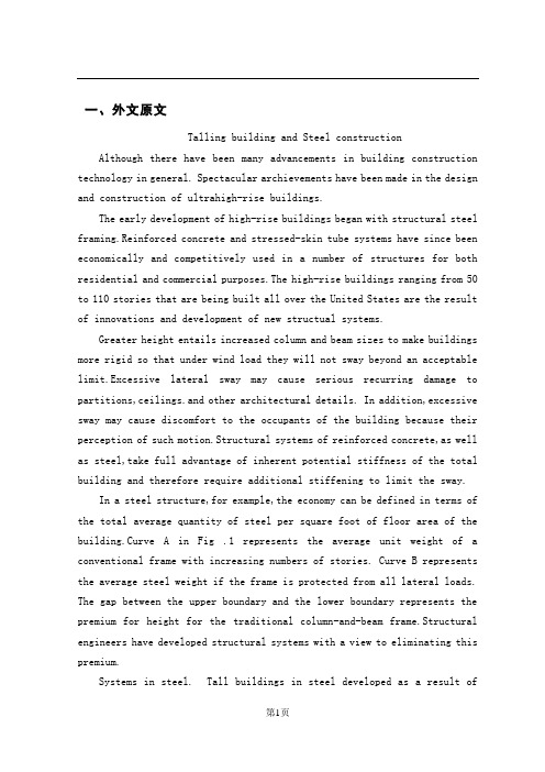
一、外文原文Talling building and Steel construction Although there have been many advancements in building construction technology in general. Spectacular archievements have been made in the design and construction of ultrahigh-rise buildings.The early development of high-rise buildings began with structural steel framing.Reinforced concrete and stressed-skin tube systems have since been economically and competitively used in a number of structures for both residential and commercial purposes.The high-rise buildings ranging from 50 to 110 stories that are being built all over the United States are the result of innovations and development of new structual systems.Greater height entails increased column and beam sizes to make buildings more rigid so that under wind load they will not sway beyond an acceptable limit.Excessive lateral sway may cause serious recurring damage to partitions,ceilings.and other architectural details. In addition,excessive sway may cause discomfort to the occupants of the building because their perception of such motion.Structural systems of reinforced concrete,as well as steel,take full advantage of inherent potential stiffness of the total building and therefore require additional stiffening to limit the sway.In a steel structure,for example,the economy can be defined in terms of the total average quantity of steel per square foot of floor area of the building.Curve A in Fig .1 represents the average unit weight of a conventional frame with increasing numbers of stories. Curve B represents the average steel weight if the frame is protected from all lateral loads. The gap between the upper boundary and the lower boundary represents the premium for height for the traditional column-and-beam frame.Structural engineers have developed structural systems with a view to eliminating this premium.Systems in steel. Tall buildings in steel developed as a result ofseveral types of structural innovations. The innovations have been applied to the construction of both office and apartment buildings.Frame with rigid belt trusses. In order to tie the exterior columns of a frame structure to the interior vertical trusses,a system of rigid belt trusses at mid-height and at the top of the building may be used. A good example of this system is the First Wisconsin Bank Building(1974) in Milwaukee.Framed tube. The maximum efficiency of the total structure of a tall building, for both strength and stiffness,to resist wind load can be achieved only if all column element can be connected to each other in such a way that the entire building acts as a hollow tube or rigid box in projecting out of the ground. This particular structural system was probably used for the first time in the 43-story reinforced concrete DeWitt Chestnut Apartment Building in Chicago. The most significant use of this system is in the twin structural steel towers of the 110-story World Trade Center building in New York Column-diagonal truss tube. The exterior columns of a building can be spaced reasonably far apart and yet be made to work together as a tube by connecting them with diagonal members interesting at the centre line of the columns and beams. This simple yet extremely efficient system was used for the first time on the John Hancock Centre in Chicago, using as much steel as is normally needed for a traditional 40-story building.Bundled tube. With the continuing need for larger and taller buildings, the framed tube or the column-diagonal truss tube may be used in a bundled form to create larger tube envelopes while maintaining high efficiency. The 110-story Sears Roebuck Headquarters Building in Chicago has nine tube, bundled at the base of the building in three rows. Some of these individual tubes terminate at different heights of the building, demonstrating the unlimited architectural possibilities of this latest structural concept. The Sears tower, at a height of 1450 ft(442m), is the world’s tallest building.Stressed-skin tube system. The tube structural system was developed for improving the resistance to lateral forces (wind and earthquake) and thecontrol of drift (lateral building movement ) in high-rise building. The stressed-skin tube takes the tube system a step further. The development of the stressed-skin tube utilizes the façade of the building as a structural element which acts with the framed tube, thus providing an efficient way of resisting lateral loads in high-rise buildings, and resulting in cost-effective column-free interior space with a high ratio of net to gross floor area.Because of the contribution of the stressed-skin façade, the framed members of the tube require less mass, and are thus lighter and less expensive. All the typical columns and spandrel beams are standard rolled shapes,minimizing the use and cost of special built-up members. The depth requirement for the perimeter spandrel beams is also reduced, and the need for upset beams above floors, which would encroach on valuable space, is minimized. The structural system has been used on the 54-story One Mellon Bank Center in Pittburgh.Systems in concrete. While tall buildings constructed of steel had an early start, development of tall buildings of reinforced concrete progressed at a fast enough rate to provide a competitive chanllenge to structural steel systems for both office and apartment buildings.Framed tube. As discussed above, the first framed tube concept for tall buildings was used for the 43-story DeWitt Chestnut Apartment Building. In this building ,exterior columns were spaced at 5.5ft (1.68m) centers, and interior columns were used as needed to support the 8-in . -thick (20-m) flat-plate concrete slabs.Tube in tube. Another system in reinforced concrete for office buildings combines the traditional shear wall construction with an exterior framed tube. The system consists of an outer framed tube of very closely spaced columns and an interior rigid shear wall tube enclosing the central service area. The system known as the tube-in-tube system , made it possible to design the world’s present tallest (714ft or 218m)lightweight concrete bu ilding( the 52-story One Shell Plaza Building in Houston) for the unit price of a traditional shear wall structure of only 35 stories.Systems combining both concrete and steel have also been developed, an examle of which is the composite system developed by skidmore, Owings &Merril in which an exterior closely spaced framed tube in concrete envelops an interior steel framing, thereby combining the advantages of both reinforced concrete and structural steel systems. The 52-story One Shell Square Building in New Orleans is based on this system.Steel construction refers to a broad range of building construction in which steel plays the leading role. Most steel construction consists of large-scale buildings or engineering works, with the steel generally in the form of beams, girders, bars, plates, and other members shaped through the hot-rolled process. Despite the increased use of other materials, steel construction remained a major outlet for the steel industries of the U.S, U.K, U.S.S.R, Japan, West German, France, and other steel producers in the 1970s.二、原文翻译高层结构与钢结构近年来,尽管一般的建筑结构设计取得了很大的进步,但是取得显著成绩的还要属超高层建筑结构设计。
土木工程--外文文献翻译

土木工程--外文文献翻译-CAL-FENGHAI.-(YICAI)-Company One1学院:专业:土木工程姓名:学号:外文出处: Structural Systems to resist (用外文写)Lateral loads附件: 1.外文资料翻译译文;2.外文原文。
附件1:外文资料翻译译文抗侧向荷载的结构体系常用的结构体系若已测出荷载量达数千万磅重,那么在高层建筑设计中就没有多少可以进行极其复杂的构思余地了。
确实,较好的高层建筑普遍具有构思简单、表现明晰的特点。
这并不是说没有进行宏观构思的余地。
实际上,正是因为有了这种宏观的构思,新奇的高层建筑体系才得以发展,可能更重要的是:几年以前才出现的一些新概念在今天的技术中已经变得平常了。
如果忽略一些与建筑材料密切相关的概念不谈,高层建筑里最为常用的结构体系便可分为如下几类:1.抗弯矩框架。
2.支撑框架,包括偏心支撑框架。
3.剪力墙,包括钢板剪力墙。
4.筒中框架。
5.筒中筒结构。
6.核心交互结构。
7. 框格体系或束筒体系。
特别是由于最近趋向于更复杂的建筑形式,同时也需要增加刚度以抵抗几力和地震力,大多数高层建筑都具有由框架、支撑构架、剪力墙和相关体系相结合而构成的体系。
而且,就较高的建筑物而言,大多数都是由交互式构件组成三维陈列。
将这些构件结合起来的方法正是高层建筑设计方法的本质。
其结合方式需要在考虑环境、功能和费用后再发展,以便提供促使建筑发展达到新高度的有效结构。
这并不是说富于想象力的结构设计就能够创造出伟大建筑。
正相反,有许多例优美的建筑仅得到结构工程师适当的支持就被创造出来了,然而,如果没有天赋甚厚的建筑师的创造力的指导,那么,得以发展的就只能是好的结构,并非是伟大的建筑。
无论如何,要想创造出高层建筑真正非凡的设计,两者都需要最好的。
虽然在文献中通常可以见到有关这七种体系的全面性讨论,但是在这里还值得进一步讨论。
设计方法的本质贯穿于整个讨论。
土木工程专业毕业设计外文文献翻译2篇
土木工程专业毕业设计外文文献翻译2篇XXXXXXXXX学院学士学位毕业设计(论文)英语翻译课题名称英语翻译学号学生专业、年级所在院系指导教师选题时间Fundamental Assumptions for Reinforced ConcreteBehaviorThe chief task of the structural engineer is the design of structures. Design is the determination of the general shape and all specific dimensions of a particular structure so that it will perform the function for which it is created and will safely withstand the influences that will act on it throughout useful life. These influences are primarily the loads and other forces to which it will be subjected, as well as other detrimental agents, such as temperature fluctuations, foundation settlements, and corrosive influences, Structural mechanics is one of the main tools in this process of design. As here understood, it is the body of scientific knowledge that permits one to predict with a good degree of certainly how a structure of give shape and dimensions will behave when acted upon by known forces or other mechanical influences. The chief items of behavior that are of practical interest are (1) the strength of the structure, i. e. , that magnitude of loads of a give distribution which will cause the structure to fail, and (2) the deformations, such as deflections and extent of cracking, that the structure will undergo when loaded underservice condition.The fundamental propositions on which the mechanics of reinforced concrete is based are as follows:1.The internal forces, such as bending moments, shear forces, and normal andshear stresses, at any section of a member are in equilibrium with the effect of the external loads at that section. This proposition is not an assumption but a fact, because any body or any portion thereof can be at rest only if all forces acting on it are in equilibrium.2.The strain in an embedded reinforcing bar is the same as that of thesurrounding concrete. Expressed differently, it is assumed that perfect bonding exists between concrete and steel at the interface, so that no slip can occur between the two materials. Hence, as the one deforms, so must the other. With modern deformed bars, a high degree of mechanical interlocking is provided in addition to the natural surface adhesion, so this assumption is very close to correct.3.Cross sections that were plane prior to loading continue to be plan in themember under load. Accurate measurements have shown that when a reinforced concrete member is loaded close to failure, this assumption is not absolutely accurate. However, the deviations are usually minor.4.In view of the fact the tensile strength of concrete is only a small fraction ofits compressive strength; the concrete in that part of a member which is in tension is usually cracked. While these cracks, in well-designed members, are generally so sorrow as to behardly visible, they evidently render the cracked concrete incapable of resisting tension stress whatever. This assumption is evidently a simplification of the actual situation because, in fact, concrete prior to cracking, as well as the concrete located between cracks, does resist tension stresses of small magnitude. Later in discussions of the resistance of reinforced concrete beams to shear, it will become apparent that under certain conditions this particular assumption is dispensed with and advantage is taken of the modest tensile strength that concrete can develop.5.The theory is based on the actual stress-strain relation ships and strengthproperties of the two constituent materials or some reasonable equivalent simplifications thereof. The fact that novelistic behavior is reflected in modern theory, that concrete is assumed to be ineffective in tension, and that the joint action of the two materials is taken into consideration results in analytical methods which are considerably more complex and also more challenging, than those that are adequate for members made of a single, substantially elastic material.These five assumptions permit one to predict by calculation the performance of reinforced concrete members only for some simple situations. Actually, the joint action of two materials as dissimilar and complicated as concrete and steel is so complex that it has not yet lent itself to purely analytical treatment. For this reason, methods of design and analysis, while using these assumptions, are very largely based on the results of extensive and continuing experimental research. They are modified and improved as additional test evidence becomes available.钢筋混凝土的基本假设作为结构工程师的主要任务是结构设计。
土木工程英文文献及翻译
Civil engineeringCivil engineering is a professional engineering discipline that deals with the design, construction, and maintenance of the physical and naturally built environment, including works like bridges, roads, canals, dams, and buildings.[1][2][3] Civil engineering is the oldest engineering discipline after military engineering,[4] and it was defined to distinguish non-military engineering from military engineering.[5] It is traditionally broken into several sub-disciplines including environmental engineering, geotechnical engineering, structural engineering, transportation engineering, municipal or urban engineering, water resources engineering, materials engineering, coastal engineering,[4] surveying, and construction engineering.[6] Civil engineering takes place on all levels: in the public sector from municipal through to national governments, and in the private sector from individual homeowners through to international companies.History of the civil engineering professionSee also: History of structural engineeringEngineering has been an aspect of life since the beginnings of human existence. The earliest practices of Civil engineering may have commenced between 4000 and 2000 BC in Ancient Egypt and Mesopotamia (Ancient Iraq) when humans started to abandon a nomadic existence, thus causing a need for the construction of shelter. During this time, transportation became increasingly important leading to the development of the wheel and sailing.Until modern times there was no clear distinction between civil engineering and architecture, and the term engineer and architect were mainly geographical variations referring to the same person, often used interchangeably.[7]The construction of Pyramids in Egypt (circa 2700-2500 BC) might be considered the first instances of large structure constructions. Other ancient historic civil engineering constructions include the Parthenon by Iktinos in Ancient Greece (447-438 BC), theAppian Way by Roman engineers (c. 312 BC), the Great Wall of China by General Meng T'ien under orders from Ch'in Emperor Shih Huang Ti (c. 220 BC)[6] and the stupas constructed in ancient Sri Lanka like the Jetavanaramaya and the extensive irrigation works in Anuradhapura. The Romans developed civil structures throughout their empire, including especially aqueducts, insulae, harbours, bridges, dams and roads.In the 18th century, the term civil engineering was coined to incorporate all things civilian as opposed to military engineering.[5]The first self-proclaimed civil engineer was John Smeaton who constructed the Eddystone Lighthouse.[4][6]In 1771 Smeaton and some of his colleagues formed the Smeatonian Society of Civil Engineers, a group of leaders of the profession who met informally over dinner. Though there was evidence of some technical meetings, it was little more than a social society.In 1818 the Institution of Civil Engineers was founded in London, and in 1820 the eminent engineer Thomas Telford became its first president. The institution received a Royal Charter in 1828, formally recognising civil engineering as a profession. Its charter defined civil engineering as:the art of directing the great sources of power in nature for the use and convenience of man, as the means of production and of traffic in states, both for external and internal trade, as applied in the construction of roads, bridges, aqueducts, canals, river navigation and docks for internal intercourse and exchange, and in the construction of ports, harbours, moles, breakwaters and lighthouses, and in the art of navigation by artificial power for the purposes of commerce, and in the construction and application of machinery, and in the drainage of cities and towns.[8] The first private college to teach Civil Engineering in the United States was Norwich University founded in 1819 by Captain Alden Partridge.[9] The first degree in Civil Engineering in the United States was awarded by Rensselaer Polytechnic Institute in 1835.[10] The first such degree to be awarded to a woman was granted by Cornell University to Nora Stanton Blatchin 1905.History of civil engineeringCivil engineering is the application of physical and scientific principles, and its history is intricately linked to advances in understanding of physics and mathematics throughout history. Because civil engineering is a wide ranging profession, including several separate specialized sub-disciplines, its history is linked to knowledge of structures, materials science, geography, geology, soils, hydrology, environment, mechanics and other fields.Throughout ancient and medieval history most architectural design and construction was carried out by artisans, such as stone masons and carpenters, rising to the role of master builder. Knowledge was retained in guilds and seldom supplanted by advances. Structures, roads and infrastructure that existed were repetitive, and increases in scale were incremental.[12]One of the earliest examples of a scientific approach to physical and mathematical problems applicable to civil engineering is the work of Archimedes in the 3rd century BC, including Archimedes Principle, which underpins our understanding of buoyancy, and practical solutions such as Archimedes' screw. Brahmagupta, an Indian mathematician, used arithmetic in the 7th century AD, based on Hindu-Arabic numerals, for excavation (volume) computations.[13]Civil engineers typically possess an academic degree with a major in civil engineering. The length of study for such a degree is usually three to five years and the completed degree is usually designated as a Bachelor of Engineering, though some universities designate the degree as a Bachelor of Science. The degree generally includes units covering physics, mathematics, project management, design and specific topics in civil engineering. Initially such topics cover most, if not all, of thesub-disciplines of civil engineering. Students then choose to specialize in one or more sub-disciplines towards the end of the degree.[14]While anUndergraduate (BEng/BSc) Degree will normally provide successful students with industry accredited qualification, some universities offer postgraduate engineering awards (MEng/MSc) which allow students to further specialize in their particular area of interest within engineering.[15]In most countries, a Bachelor's degree in engineering represents the first step towards professional certification and the degree program itself is certified by a professional body. After completing a certified degree program the engineer must satisfy a range of requirements (including work experience and exam requirements) before being certified. Once certified, the engineer is designated the title of Professional Engineer (in the United States, Canada and South Africa), Chartered Engineer (in most Commonwealth countries), Chartered Professional Engineer (in Australia and New Zealand), or European Engineer (in much of the European Union). There are international engineering agreements between relevant professional bodies which are designed to allow engineers to practice across international borders.The advantages of certification vary depending upon location. For example, in the United States and Canada "only a licensed engineer may prepare, sign and seal, and submit engineering plans and drawings to a public authority for approval, or seal engineering work for public and private clients.".[16]This requirement is enforced by state and provincial legislation such as Quebec's Engineers Act.[17]In other countries, no such legislation exists. In Australia, state licensing of engineers is limited to the state of Queensland. Practically all certifying bodies maintain a code of ethics that they expect all members to abide by or risk expulsion.[18] In this way, these organizations play an important role in maintaining ethical standards for the profession. Even in jurisdictions where certification has little or no legal bearing on work, engineers are subject to contract law. In cases where an engineer's work fails he or she may be subject to the tort of negligence and, in extreme cases, thecharge of criminal negligence.[citation needed] An engineer's work must also comply with numerous other rules and regulations such as building codes and legislation pertaining to environmental law.CareersThere is no one typical career path for civil engineers. Most people who graduate with civil engineering degrees start with jobs that require a low level of responsibility, and as the new engineers prove their competence, they are trusted with tasks that have larger consequences and require a higher level of responsibility. However, within each branch of civil engineering career path options vary. In some fields and firms, entry-level engineers are put to work primarily monitoring construction in the field, serving as the "eyes and ears" of senior design engineers; while in other areas, entry-level engineers perform the more routine tasks of analysis or design and interpretation. Experienced engineers generally do more complex analysis or design work, or management of more complex design projects, or management of other engineers, or into specialized consulting, including forensic engineering.In general, civil engineering is concerned with the overall interface of human created fixed projects with the greater world. General civil engineers work closely with surveyors and specialized civil engineers to fit and serve fixed projects within their given site, community and terrain by designing grading, drainage, pavement, water supply, sewer service, electric and communications supply, and land divisions. General engineers spend much of their time visiting project sites, developing community consensus, and preparing construction plans. General civil engineering is also referred to as site engineering, a branch of civil engineering that primarily focuses on converting a tract of land from one usage to another. Civil engineers typically apply the principles of geotechnical engineering, structural engineering, environmental engineering, transportation engineering and construction engineering toresidential, commercial, industrial and public works projects of all sizes and levels of construction翻译:土木工程土木工程是一个专业的工程学科,包括设计,施工和维护与环境的改造,涉及了像桥梁,道路,河渠,堤坝和建筑物工程交易土木工程是最古老的军事工程后,工程学科,它被定义为区分军事工程非军事工程的学科它传统分解成若干子学科包括环境工程,岩土工程,结构工程,交通工程,市或城市工程,水资源工程,材料工程,海岸工程,勘测和施工工程等土木工程的范围涉及所有层次:从市政府到国家,从私人部门到国际公司。
土木工程外文翻译-原文
外文原文Response of a reinforced concrete infilled—frame structure to removal of twoadjacent columnsMehrdad Sasani_Northeastern University, 400 Snell Engineering Center,Boston,MA 02115, UnitedStatesReceived 27 June 2007;received in revised form 26 December 2007;accepted 24January 2008Available online 19 March 2008AbstractThe response of Hotel San Diego,a six—story reinforced concrete infilled-frame structure,is evaluated following the simultaneous removal of two adjacent exterior columns. Analytical models of the structure using the Finite Element Method as well as the Applied Element Method are used to calculate global and local deformations. The analytical results show good agreement with experimental data. The structure resisted progressive collapse with a measured maximum vertical displacement of only one quarter of an inch (6.4 mm)。
土木工程英语文献原文及中文翻译
Civil engineering introduction papers[英语原文]Abstract: the civil engineering is a huge discipline, but the main one is building, building whether in China or abroad, has a long history, long-term development process. The world is changing every day, but the building also along with the progress of science and development. Mechanics findings, material of update, ever more scientific technology into the building. But before a room with a tile to cover the top of the house, now for comfort, different ideas, different scientific, promoted the development of civil engineering, making it more perfect.[key words] : civil engineering; Architecture; Mechanics, Materials.Civil engineering is build various projects collectively. It was meant to be and "military project" corresponding. In English the history of Civil Engineering, mechanical Engineering, electrical Engineering, chemical Engineering belong to to Engineering, because they all have MinYongXing. Later, as the project development of science and technology, mechanical, electrical, chemical has gradually formed independent scientific, to Engineering became Civil Engineering of specialized nouns. So far, in English, to Engineering include water conservancy project, port Engineering, While in our country, water conservancy projects and port projects also become very close and civil engineering relatively independent branch. Civil engineering construction of object, both refers to that built on the ground, underground water engineering facilities, also refers to applied materials equipment and conduct of the investigation, design and construction, maintenance, repair and other professional technology.Civil engineering is a kind of with people's food, clothing, shelter and transportation has close relation of the project. Among them with "live" relationship is directly. Because, to solve the "live" problem must build various types of buildings. To solve the "line, food and clothes" problem both direct side, but also a indirect side. "Line", must build railways, roads, Bridges, "Feed", must be well drilling water, water conservancy, farm irrigation, drainage water supply for the city, that is direct relation. Indirectly relationship is no matter what you do, manufacturing cars, ships, or spinning and weaving, clothing, or even production steel, launch satellites, conducting scientific research activities are inseparable from build various buildings, structures and build all kinds of project facilities.Civil engineering with the progress of human society and development, yet has evolved into large-scale comprehensive discipline, it has out many branch, such as: architectural engineering, the railway engineering, road engineering, bridge engineering, special engineering structure, waterand wastewater engineering, port engineering, hydraulic engineering, environment engineering disciplines. [1]Civil engineering as an important basic disciplines, and has its important attributes of: integrated, sociality, practicality, unity. Civil engineering for the development of national economy and the improvement of people's life provides an important material and technical basis, for many industrial invigoration played a role in promoting, engineering construction is the formation of a fixed asset basic production process, therefore, construction and real estate become in many countries and regions, economic powerhouses.Construction project is housing planning, survey, design, construction of the floorboard. Purpose is for human life and production provide places.Houses will be like a man, it's like a man's life planning environment is responsible by the planners, Its layout and artistic processing, corresponding to the body shape looks and temperament, is responsible by the architect, Its structure is like a person's bones and life expectancy, the structural engineer is responsible, Its water, heating ventilation and electrical facilities such as the human organ and the nerve, is by the equipment engineer is responsible for. Also like nature intact shaped like people, in the city I district planning based on build houses, and is the construction unit, reconnaissance unit, design unit of various design engineers and construction units comprehensive coordination and cooperation process.After all, but is structural stress body reaction force and the internal stress and how external force balance. Building to tackle, also must solve the problem is mechanical problems. We have to solve the problem of discipline called architectural mechanics. Architectural mechanics have can be divided into: statics, material mechanics and structural mechanics three mechanical system. Architectural mechanics is discussion and research building structure and component in load and other factors affecting the working condition of, also is the building of intensity, stiffness and stability. In load, bear load and load of structure and component can cause the surrounding objects in their function, and the object itself by the load effect and deformation, and there is the possibility of damage, but the structure itself has certain resistance to deformation and destruction of competence, and the bearing capacity of the structure size is and component of materials, cross section, and the structural properties of geometry size, working conditions and structure circumstance relevant. While these relationships can be improved by mechanics formula solved through calculation.Building materials in building and has a pivotal role. Building material is with human society productivity and science and technologyimproves gradually developed. In ancient times, the human lives, the line USES is the rocks andTrees. The 4th century BC, 12 ~ has created a tile and brick, humans are only useful synthetic materials made of housing. The 17th century had cast iron and ShouTie later, until the eighteenth century had Portland cement, just make later reinforced concrete engineering get vigorous development. Now all sorts of high-strength structural materials, new decoration materials and waterproof material development, criterion and 20th century since mid organic polymer materials in civil engineering are closely related to the widely application. In all materials, the most main and most popular is steel, concrete, lumber, masonry. In recent years, by using two kinds of material advantage, will make them together, the combination of structure was developed. Now, architecture, engineering quality fit and unfit quality usually adopted materials quality, performance and using reasonable or not have direct connection, in meet the same technical indicators and quality requirements, under the precondition of choice of different material is different, use method of engineering cost has direct impact.In construction process, building construction is and architectural mechanics, building materials also important links. Construction is to the mind of the designer, intention and idea into realistic process, from the ancient hole JuChao place to now skyscrapers, from rural to urban country road elevated road all need through "construction" means. A construction project, including many jobs such as dredging engineering, deep foundation pit bracing engineering, foundation engineering, reinforced concrete structure engineering, structural lifting project, waterproofing, decorate projects, each type of project has its own rules, all need according to different construction object and construction environment conditions using relevant construction technology, in work-site.whenever while, need and the relevant hydropower and other equipment composition of a whole, each project between reasonable organizing and coordination, better play investment benefit. Civil engineering construction in the benefit, while also issued by the state in strict accordance with the relevant construction technology standard, thus further enhance China's construction level to ensure construction quality, reduce the cost for the project.Any building built on the surface of the earth all strata, building weight eventually to stratum, have to bear. Formation Support building the rocks were referred to as foundation, and the buildings on the ground and under the upper structure of self-respect and liable to load transfer to the foundation of components or component called foundation. Foundation, and the foundation and the superstructure is a building of three inseparable part. According to the function is different, but in load, under the action of them are related to each other, is theinteraction of the whole. Foundation can be divided into natural foundation and artificial foundation, basic according to the buried depth is divided into deep foundation and shallow foundation. , foundation and foundation is the guarantee of the quality of the buildings and normal use close button, where buildings foundation in building under loads of both must maintain overall stability and if the settlement of foundation produce in building scope permitted inside, and foundation itself should have sufficient strength, stiffness and durability, also consider repair methods and the necessary foundation soil retaining retaining water and relevant measures. [3]As people living standard rise ceaselessly, the people to their place of building space has become not only from the number, and put forward higher requirement from quality are put car higher demands that the environment is beautiful, have certain comfort. This needs to decorate a building to be necessary. If architecture major engineering constitutes the skeleton of the building, then after adornment building has become the flesh-and-blood organism, final with rich, perfect appearance in people's in front, the best architecture should fully embody all sorts of adornment material related properties, with existing construction technology, the most effective gimmick, to achieve conception must express effect. Building outfit fix to consider the architectural space use requirement, protect the subject institutions from damage, give a person with beautifulenjoying, satisfy the requirements of fire evacuation, decorative materials and scheme of rationality, construction technology and economic feasibility, etc. Housing construction development and at the same time, like housing construction as affecting people life of roads, Bridges, tunnels has made great progress.In general civil engineering is one of the oldest subjects, it has made great achievements, the future of the civil engineering will occupy in people's life more important position. The environment worsening population increase, people to fight for survival, to strive for a more comfortable living environment, and will pay more attention to civil engineering. In the near future, some major projects extimated to build, insert roller skyscrapers, across the oceanBridges, more convenient traffic would not dream. The development of science and technology, and the earth is deteriorating environment will be prompted civil engineering to aerospace and Marine development, provide mankind broader space of living. In recent years, engineering materials mainly is reinforced concrete, lumber and brick materials, in the future, the traditional materials will be improved, more suitable for some new building materials market, especially the chemistry materials will promote the construction of towards a higher point. Meanwhile, design method of precision, design work of automation, information and intelligent technology of introducing, will be people have a morecomfortable living environment. The word, and the development of the theory and new materials, the emergence of the application of computer, high-tech introduction to wait to will make civil engineering have a new leap.This is a door needs calm and a great deal of patience and attentive professional. Because hundreds of thousands, even hundreds of thousands of lines to building each place structure clearly reflected. Without a gentle state of mind, do what thing just floating on the surface, to any a building structure, to be engaged in business and could not have had a clear, accurate and profound understanding of, the nature is no good. In this business, probably not burn the midnight oil of courage, not to reach the goal of spirit not to give up, will only be companies eliminated.This is a responsible and caring industry. Should have a single responsible heart - I one's life in my hand, thousands of life in my hand. Since the civil, should choose dependably shoulder the responsibility.Finally, this is a constant pursuit of perfect industry. Pyramid, spectacular now: The Great Wall, the majestic... But if no generations of the pursuit of today, we may also use the sort of the oldest way to build this same architecture. Design a building structure is numerous, but this is all experienced centuries of clarification, through continuous accumulation, keep improving, innovation obtained. And such pursuit, not confined in the past. Just think, if the design of a building can be like calculation one plus one equals two as simple and easy to grasp, that was not for what? Therefore, a civil engineer is in constant of in formation. One of the most simple structure, the least cost, the biggest function. Choose civil, choosing a steadfast diligence, innovation, pursuit of perfect path.Reference:[1] LuoFuWu editor. Civil engineering (professional). Introduction to wuhan. Wuhan university of technology press. 2007[2] WangFuChuan, palace rice expensive editor. Construction engineering materials. Beijing. Science and technology literature press. 2002[3] jiang see whales, zhiming editor. Civil engineering introduction of higher education press. Beijing.. 1992土木工程概论 [译文]摘要:土木工程是个庞大的学科,但最主要的是建筑,建筑无论是在中国还是在国外,都有着悠久的历史,长期的发展历程。
土木工程专业毕业设计外文文献及翻译
英文原文:Rehabilitation of rectangular simply supported RC beams with shear deficiencies using CFRP compositesAhmed Khalifa a,*, Antonio Nanni ba Department of Structural Engineering,University of Alexandria,Alexandria 21544,Egyptb Department of Civil Engineering,University of Missouri at Rolla,Rolla,MO 65409,USAReceived 28 April 1999;received in revised form 30 October 2001;accepted 10 January 2002AbstractThe present study examines the shear performance and modes of failure of rectangular simply supported reinforced concrete(RC) beams designed with shear deficiencies。
These members were strengthened with externally bonded carbon fiber reinforced polymer (CFRP)sheets and evaluated in the laboratory. The experimental program consisted of twelve full—scale RC beams tested to fail in shear. The variables investigated within this program included steel stirrups, and the shear span-to—effective depth ratio, as well as amount and distribution of CFRP。
- 1、下载文档前请自行甄别文档内容的完整性,平台不提供额外的编辑、内容补充、找答案等附加服务。
- 2、"仅部分预览"的文档,不可在线预览部分如存在完整性等问题,可反馈申请退款(可完整预览的文档不适用该条件!)。
- 3、如文档侵犯您的权益,请联系客服反馈,我们会尽快为您处理(人工客服工作时间:9:00-18:30)。
学院:专业:土木工程姓名:学号:外文出处: Structural Systems to resist (用外文写)Lateral loads附件: 1.外文资料翻译译文;2.外文原文。
附件1:外文资料翻译译文抗侧向荷载的结构体系常用的结构体系若已测出荷载量达数千万磅重,那么在高层建筑设计中就没有多少可以进行极其复杂的构思余地了。
确实,较好的高层建筑普遍具有构思简单、表现明晰的特点。
这并不是说没有进行宏观构思的余地。
实际上,正是因为有了这种宏观的构思,新奇的高层建筑体系才得以发展,可能更重要的是:几年以前才出现的一些新概念在今天的技术中已经变得平常了。
如果忽略一些与建筑材料密切相关的概念不谈,高层建筑里最为常用的结构体系便可分为如下几类:1.抗弯矩框架。
2.支撑框架,包括偏心支撑框架。
3.剪力墙,包括钢板剪力墙。
4.筒中框架。
5.筒中筒结构。
6.核心交互结构。
7. 框格体系或束筒体系。
特别是由于最近趋向于更复杂的建筑形式,同时也需要增加刚度以抵抗几力和地震力,大多数高层建筑都具有由框架、支撑构架、剪力墙和相关体系相结合而构成的体系。
而且,就较高的建筑物而言,大多数都是由交互式构件组成三维陈列。
将这些构件结合起来的方法正是高层建筑设计方法的本质。
其结合方式需要在考虑环境、功能和费用后再发展,以便提供促使建筑发展达到新高度的有效结构。
这并不是说富于想象力的结构设计就能够创造出伟大建筑。
正相反,有许多例优美的建筑仅得到结构工程师适当的支持就被创造出来了,然而,如果没有天赋甚厚的建筑师的创造力的指导,那么,得以发展的就只能是好的结构,并非是伟大的建筑。
无论如何,要想创造出高层建筑真正非凡的设计,两者都需要最好的。
虽然在文献中通常可以见到有关这七种体系的全面性讨论,但是在这里还值得进一步讨论。
设计方法的本质贯穿于整个讨论。
设计方法的本质贯穿于整个讨论中。
抗弯矩框架抗弯矩框架也许是低,中高度的建筑中常用的体系,它具有线性水平构件和垂直构件在接头处基本刚接之特点。
这种框架用作独立的体系,或者和其他体系结合起来使用,以便提供所需要水平荷载抵抗力。
对于较高的高层建筑,可能会发现该本系不宜作为独立体系,这是因为在侧向力的作用下难以调动足够的刚度。
我们可以利用STRESS,STRUDL 或者其他大量合适的计算机程序进行结构分析。
所谓的门架法分析或悬臂法分析在当今的技术中无一席之地,由于柱梁节点固有柔性,并且由于初步设计应该力求突出体系的弱点,所以在初析中使用框架的中心距尺寸设计是司空惯的。
当然,在设计的后期阶段,实际地评价结点的变形很有必要。
支撑框架支撑框架实际上刚度比抗弯矩框架强,在高层建筑中也得到更广泛的应用。
这种体系以其结点处铰接或则接的线性水平构件、垂直构件和斜撑构件而具特色,它通常与其他体系共同用于较高的建筑,并且作为一种独立的体系用在低、中高度的建筑中。
尤其引人关注的是,在强震区使用偏心支撑框架。
此外,可以利用STRESS,STRUDL,或一系列二维或三维计算机分析程序中的任何一种进行结构分析。
另外,初步分析中常用中心距尺寸。
剪力墙剪力墙在加强结构体系刚性的发展过程中又前进了一步。
该体系的特点是具有相当薄的,通常是(而不总是)混凝土的构件,这种构件既可提供结构强度,又可提供建筑物功能上的分隔。
在高层建筑中,剪力墙体系趋向于具有相对大的高宽经,即与宽度相比,其高度偏大。
由于基础体系缺少应力,任何一种结构构件抗倾覆弯矩的能力都受到体系的宽度和构件承受的重力荷载的限制。
由于剪力墙宽度狭狭窄受限,所以需要以某种方式加以扩大,以便提从所需的抗倾覆能力。
在窗户需要量小的建筑物外墙中明显地使用了这种确有所需要宽度的体系。
钢结构剪力墙通常由混凝土覆盖层来加强以抵抗失稳,这在剪切荷载大的地方已得到应用。
这种体系实际上比钢支撑经济,对于使剪切荷载由位于地面正上方区域内比较高的楼层向下移特别有效。
这种体系还具有高延性之优点,这种特性在强震区特别重要。
由于这些墙内必然出同一些大孔,使得剪力墙体系分析变得错综复杂。
可以通过桁架模似法、有限元法,或者通过利用为考虑剪力墙的交互作用或扭转功能设计的专门计处机程序进行初步分析。
框架或支撑式筒体结构:框架或支撑式筒体最先应用于IBM公司在Pittsburgh的一幢办公楼,随后立即被应用于纽约双子座的110层世界贸易中心摩天大楼和其他的建筑中。
这种系统有以下几个显著的特征:三维结构、支撑式结构、或由剪力墙形成的一个性质上差不多是圆柱体的闭合曲面,但又有任意的平面构成。
由于这些抵抗侧向荷载的柱子差不多都被设置在整个系统的中心,所以整体的惯性得到提高,刚度也是很大的。
在可能的情况下,通过三维概念的应用、二维的类比,我们可以进行筒体结构的分析。
不管应用那种方法,都必须考虑剪力滞后的影响。
这种最先在航天器结构中研究的剪力滞后出现后,对筒体结构的刚度是一个很大的限制。
这种观念已经影响了筒体结构在60层以上建筑中的应用。
设计者已经开发出了很多的技术,用以减小剪力滞后的影响,这其中最有名的是桁架的应用。
框架或支撑式筒体在40层或稍高的建筑中找到了自己的用武之地。
除了一些美观的考虑外,桁架几乎很少涉及与外墙联系的每个建筑功能,而悬索一般设置在机械的地板上,这就令机械体系设计师们很不赞成。
但是,作为一个性价比较好的结构体系,桁架能充分发挥它的性能,所以它会得到设计师们持续的支持。
由于其最佳位置正取决于所提供的桁架的数量,因此很多研究已经试图完善这些构件的位置。
实验表明:由于这种结构体系的经济性并不十分受桁架位置的影响,所以这些桁架的位置主要取决于机械系统的完善,审美的要求,筒中筒结构:筒体结构系统能使外墙中的柱具有灵活性,用以抵抗颠覆和剪切力。
“筒中筒”这个名字顾名思义就是在建筑物的核心承重部分又被包围了第二层的一系列柱子,它们被当作是框架和支撑筒来使用。
配置第二层柱的目的是增强抗颠覆能力和增大侧移刚度。
这些筒体不是同样的功能,也就是说,有些筒体是结构的,而有些筒体是用来支撑的。
在考虑这种筒体时,清楚的认识和区别变形的剪切和弯曲分量是很重要的,这源于对梁的对比分析。
在结构筒中,剪切构件的偏角和柱、纵梁(例如:结构筒中的网等)的弯曲有关,同时,弯曲构件的偏角取决于柱子的轴心压缩和延伸(例如:结构筒的边缘等)。
在支撑筒中,剪切构件的偏角和对角线的轴心变形有关,而弯曲构件的偏角则与柱子的轴心压缩和延伸有关。
根据梁的对比分析,如果平面保持原形(例如:厚楼板),那么外层筒中柱的轴心压力就会与中心筒柱的轴心压力相差甚远,而且稳定的大于中心筒。
但是在筒中筒结构的设计中,当发展到极限时,内部轴心压力会很高的,甚至远远大于外部的柱子。
这种反常的现象是由于两种体系中的剪切构件的刚度不同。
这很容易去理解,内筒可以看成是一个支撑(或者说是剪切刚性的)筒,而外筒可以看成是一个结构(或者说是剪切弹性的)筒。
核心交互式结构:核心交互式结构属于两个筒与某些形式的三维空间框架相配合的筒中筒特殊情况。
事实上,这种体系常用于那种外筒剪切刚度为零的结构。
位于Pittsburgh的美国钢铁大楼证实了这种体系是能很好的工作的。
在核心交互式结构中,内筒是一个支撑结构,外筒没有任何剪切刚度,而且两种结构体系能通过一个空间结构或“帽”式结构共同起作用。
需要指出的是,如果把外部的柱子看成是一种从“帽”到基础的直线体系,这将是不合适的;根据支撑核心的弹性曲线,这些柱子只发挥了刚度的15%。
同样需要指出的是,内柱中与侧向力有关的轴向力沿筒高度由拉力变为压力,同时变化点位于筒高度的约5/8处。
当然,外柱也传递相同的轴向力,这种轴向力低于作用在整个柱子高度的侧向荷载,因为这个体系的剪切刚度接近于零。
把内外筒相连接的空间结构、悬臂梁或桁架经常遵照一些规范来布置。
美国电话电报总局就是一个布置交互式构件的生动例子。
1.结构体系长59.7米,宽28.6米,高183.3米。
2.布置了两个筒,每个筒的尺寸是9.4米×12.2米,在长方向上有27.4米的间隔。
3. 在短方向上内筒被支撑起来,但是在长方向上没有剪切刚度。
4. 环绕着建筑物布置了一个外筒。
5. 外筒是一个瞬时抵抗结构,但是在每个长方向的中心15.2米都没有剪切刚度。
6.在建筑的顶部布置了一个空间桁架构成的“帽式”结构。
7.在建筑的底部布置了一个相似的空间桁架结构。
8.由于外筒的剪切刚度在建筑的底部接近零,整个建筑基本上由两个钢板筒来支持。
框格体系或束筒体系结构:位于美国芝加哥的西尔斯大厦是箱式结构的经典之作,它由九个相互独立的筒组成的一个集中筒。
由于西尔斯大厦包括九个几乎垂直的筒,而且筒在平面上无须相似,基本的结构体系在不规则形状的建筑中得到特别的应用。
一些单个的筒高于建筑一点或很多是很常见的。
事实上,这种体系的重要特征就在于它既有坚固的一面,也有脆弱的一面。
这种体系的脆弱,特别是在结构筒中,与柱子的压缩变形有很大的关系,柱子的压缩变形有下式计算:△=ΣfL/E对于那些层高为3.66米左右和平均压力为138MPa的建筑,在荷载作用下每层柱子的压缩变形为15(12)/29000或1.9毫米。
在第50层柱子会压缩94毫米,小于它未受压的长度。
这些柱子在50层的时候和100层的时候的变形是不一样的,位于这两种体系之间接近于边缘的那些柱需要使这种不均匀的变形得以调解。
主要的结构工作都集中在布置中。
在Melbourne的Rialto项目中,结构工程师发现至少有一幢建筑,很有必要垂直预压低高度的柱子,以便使柱不均匀的变形差得以调解,调解的方法近似于后拉伸法,即较短的柱转移重量到较高的邻柱上。
附件2:外文原文(复印件)Structural Systems to resist lateral loadsCommonly Used structural SystemsWith loads measured in tens of thousands kips, there is little room in the design of high-rise buildings for excessively complex thoughts. Indeed, the better high-rise buildings carry the universal traits of simplicity of thought and clarity of expression.It does not follow that there is no room for grand thoughts. Indeed, it is with such grand thoughts that the new family of high-rise buildings has evolved. Perhaps more important, the new concepts of but a few years ago have become commonplace in today’ s technology.Omitting some concepts that are related strictly to the materials of construction, the most commonly used structural systems used in high-rise buildings can be categorized as follows:1.Moment-resisting frames.2.Braced frames, including eccentrically braced frames.3.Shear walls, including steel plate shear walls.4.Tube-in-tube structures.5.Tube-in-tube structures.6.Core-interactive structures.7.Cellular or bundled-tube systems.Particularly with the recent trend toward more complex forms, but in response also to the need for increased stiffness to resist the forces from wind and earthquake, most high-rise buildings have structural systems built up of combinations of frames, braced bents, shear walls, and related systems. Further, for the taller buildings, the majorities are composed of interactive elements in three-dimensional arrays.The method of combining these elements is the very essence of the design process for high-rise buildings. These combinations need evolve in response to environmental, functional, and cost considerations so as to provide efficient structures that provoke the architectural development to new heights. This is not to say that imaginative structural design can create great architecture. To the contrary, many examples of fine architecture have been created with only moderate support from the structural engineer, while only fine structure, not great architecture, can be developed without the genius and theleadership of a talented architect. In any event, the best of both is needed to formulate a truly extraordinary design of a high-rise building.While comprehensive discussions of these seven systems are generally available in the literature, further discussion is warranted here .The essence of the design process is distributed throughout the discussion.Moment-Resisting FramesPerhaps the most commonly used system in low-to medium-rise buildings, the moment-resisting frame, is characterized by linear horizontal and vertical members connected essentially rigidly at their joints. Such frames are used as a stand-alone system or in combination with other systems so as to provide the needed resistance to horizontal loads. In the taller of high-rise buildings, the system is likely to be found inappropriate for a stand-alone system, this because of the difficulty in mobilizing sufficient stiffness under lateral forces.Analysis can be accomplished by STRESS, STRUDL, or a host of other appropriate computer programs; analysis by the so-called portal method of the cantilever method has no place in today’s technology.Because of the intrinsic flexibility of the column/girder intersection, and because preliminary designs should aim to highlight weaknesses of systems, it is not unusual to use center-to-center dimensions for the frame in the preliminary analysis. Of course, in the latter phases of design, a realistic appraisal in-joint deformation is essential.Braced Frame sThe braced frame, intrinsically stiffer than the moment –resisting frame, finds also greater application to higher-rise buildings. The system is characterized by linear horizontal, vertical, and diagonal members, connected simply or rigidly at their joints. It is used commonly in conjunction with other systems for taller buildings and as a stand-alone system in low-to medium-rise buildings.While the use of structural steel in braced frames is common, concrete frames are more likely to be of the larger-scale variety.Of special interest in areas of high seismicity is the use of the eccentric braced frame.Again, analysis can be by STRESS, STRUDL, or any one of a series of two –or three dimensional analysis computer programs. And again, center-to-center dimensions are used commonly in the preliminary analysis.Shear wallsThe shear wall is yet another step forward along a progression of ever-stiffer structural systems. The system is characterized by relatively thin, generally (but not always) concrete elements that provide both structural strength and separation between building functions.In high-rise buildings, shear wall systems tend to have a relatively high aspect ratio, that is, their height tends to be large compared to their width. Lacking tension in the foundation system, any structural element is limited in its ability to resist overturning moment by the width of the system and by the gravity load supported by the element. Limited to a narrow overturning, One obvious use of the system, which does have the needed width, is in the exterior walls of building, where the requirement for windows is kept small.Structural steel shear walls, generally stiffened against buckling by a concrete overlay, have found application where shear loads are high. The system, intrinsically more economical than steel bracing, is particularly effective in carrying shear loads down through the taller floors in the areas immediately above grade. The sys tem has the further advantage of having high ductility a feature of particular importance in areas of high seismicity.The analysis of shear wall systems is made complex because of the inevitable presence of large openings through these walls. Preliminary analysis can be by truss-analogy, by the finite element method, or by making use of a proprietary computer program designed to consider the interaction, or coupling, of shear walls.Framed or Braced TubesThe concept of the framed or braced or braced tube erupted into the technology with the IBM Building in Pittsburgh, but was followed immediately with the twin 110-story towers of the World Trade Center, New York and a number of other buildings .The system is characterized by three –dimensional frames, braced frames, or shear walls, forming a closed surface more or less cylindrical in nature, but of nearly anyplan configuration. Because those columns that resist lateral forces are placed as far as possible from the cancroids of the system, the overall moment of inertia is increased and stiffness is very high.The analysis of tubular structures is done using three-dimensional concepts, or by two- dimensional analogy, where possible, whichever method is used, it must be capable of accounting for the effects of shear lag.The presence of shear lag, detected first in aircraft structures, is a serious limitation in the stiffness of framed tubes. The concept has limited recent applications of framed tubes to the shear of 60 stories. Designers have developed various techniques for reducing the effects of shear lag, most noticeably the use of belt trusses. This system finds application in buildings perhaps 40stories and higher. However, except for possible aesthetic considerations, belt trusses interfere with nearly every building function associated with the outside wall; the trusses are placed often at mechanical floors, mush to the disapproval of the designers of the mechanical systems. Nevertheless, as a cost-effective structural system, the belt truss works well and will likely find continued approval from designers. Numerous studies have sought to optimize the location of these trusses, with the optimum location very dependent on the number of trusses provided. Experience would indicate, however, that the location of these trusses is provided by the optimization of mechanical systems and by aesthetic considerations, as the economics of the structural system is not highly sensitive to belt truss location.Tube-in-Tube StructuresThe tubular framing system mobilizes every column in the exterior wall in resisting over-turning and shearing forces. The term‘tube-in-tube’is largely self-explanatory in that a second ring of columns, the ring surrounding the central service core of the building, is used as an inner framed or braced tube. The purpose of the second tube is to increase resistance to over turning and to increase lateral stiffness. The tubes need not be of the same character; that is, one tube could be framed, while the other could be braced.In considering this system, is important to understand clearly the difference between the shear and the flexural components of deflection, the terms being taken from beam analogy. In a framed tube, the shear component of deflection is associated with the bending deformation of columns and girders (i.e, the webs of the framed tube) while the flexural component is associated with the axial shortening and lengthening of columns (i.e, the flanges of the framed tube). In a braced tube, the shear component of deflection isassociated with the axial deformation of diagonals while the flexural component of deflection is associated with the axial shortening and lengthening of columns.Following beam analogy, if plane surfaces remain plane (i.e, the floor slabs),then axial stresses in the columns of the outer tube, being farther form the neutral axis, will be substantially larger than the axial stresses in the inner tube. However, in the tube-in-tube design, when optimized, the axial stresses in the inner ring of columns may be as high, or even higher, than the axial stresses in the outer ring. This seeming anomaly is associated with differences in the shearing component of stiffness between the two systems. This is easiest to under-stand where the inner tube is conceived as a braced (i.e, shear-stiff) tube while the outer tube is conceived as a framed (i.e, shear-flexible) tube.Core Interactive StructuresCore interactive structures are a special case of a tube-in-tube wherein the two tubes are coupled together with some form of three-dimensional space frame. Indeed, the system is used often wherein the shear stiffness of the outer tube is zero. The United States Steel Building, Pittsburgh, illustrates the system very well. Here, the inner tube is a braced frame, the outer tube has no shear stiffness, and the two systems are coupled if they were considered as systems passing in a straight line from the “hat” structure. Note that the exterior columns would be improperly modeled if they were considered as systems passing in a straight line from the “hat” to the foundations; these columns are perhaps 15% stiffer as they follow the elastic curve of the braced core. Note also that the axial forces associated with the lateral forces in the inner columns change from tension to compression over the height of the tube, with the inflection point at about 5/8 of the height of the tube. The outer columns, of course, carry the same axial force under lateral load for the full height of the columns because the columns because the shear stiffness of the system is close to zero. The space structures of outrigger girders or trusses, that connect the inner tube to the outer tube, are located often at several levels in the building. The A T&T headquarters is an example of an astonishing array of interactive elements:1.The structural system is 94 ft (28.6m) wide, 196ft(59.7m) long, and 601ft (183.3m) high.2.Two inner tubes are provided, each 31ft(9.4m) by 40 ft (12.2m), centered 90 ft (27.4m) apart in thelong direction of the building.3.The inner tubes are braced in the short direction, but with zero shear stiffness in the long direction.4. A single outer tube is supplied, which encircles the building perimeter.5.The outer tube is a moment-resisting frame, but with zero shear stiffness for the center50ft (15.2m)of each of the long sides.6. A space-truss hat structure is provided at the top of the building.7. A similar space truss is located near the bottom of the building8.The entire assembly is laterally supported at the base on twin steel-plate tubes, because the shearstiffness of the outer tube goes to zero at the base of the building.Cellular structuresA classic example of a cellular structure is the Sears Tower, Chicago, a bundled tube structure of nine separate tubes. While the Sears Tower contains nine nearly identical tubes, the basic structural system has special application for buildings of irregular shape, as the several tubes need not be similar in plan shape, It is not uncommon that some of the individual tubes one of the strengths and one of the weaknesses of the system.This special weakness of this system, particularly in framed tubes, has to do with the concept of differential column shortening. The shortening of a column under load is given by the expression△=ΣfL/EFor buildings of 12 ft (3.66m) floor-to-floor distances and an average compressive stress of 15 ksi (138MPa), the shortening of a column under load is 15 (12)(12)/29,000 or 0.074in (1.9mm) per story. At 50 stories, the column will have shortened to 3.7 in. (94mm) less than its unstressed length. Where one cell of a bundled tube system is, say, 50stories high and an adjacent cell is, say, 100stories high, those columns near the boundary between .the two systems need to have this differential deflection reconciled. Major structural work has been found to be needed at such locations. In at least one building, the Rialto Project, Melbourne, the structural engineer found it necessary to vertically pre-stress the lower height columns so as to reconcile the differential deflections of columns in close proximity with the post-tensioning of the shorter column simulating the weight to be added on to adjacent, higher columns.。