恩乐曼SS2U通讯协议
USS 协议应用基本概念

USS 协议应用基本概念SS 协议应用基本概念ZaneUSS 协议简介USS 协议(Universal Serial Interface Protocol 通用串行接口协议)是SIEMENS 公司所有传动产品的通用通讯协议,它是一种基于串行总线进行数据通讯的协议。
USS协议是主-从结构的协议,规定了在USS 总线上可以有一个主站和最多30 个从站;总线上的每个从站都有一个站地址(在从站参数中设定),主站依靠它识别每个从站;每个从站也只对主站发来的报文做出响应并回送报文,从站之间不能直接进行数据通讯。
另外,还有一种广播通讯方式,主站可以同时给所有从站发送报文,从站在接收道报文并做出相应的响应后可不回送报文。
使用USS 协议的优点1. 对硬件设备要求低,减少了设备之间的布线,2. 无需重新连线就可以改变控制功能,3. 可通过串行接口设置或改变传动装置的参数,4. 可实时的监控传动系统常用USS 主站的性能对比产品通讯接口最大通讯波特率CPU 22X 9 芯D 型插头115.2K bpsCPU 31XC-PTP 15 芯D 型插头19.2K bpsCP 340-C 15 芯D 型插头9.6K bpsCP 341-C 15 芯D 型插头19.2K bps可见,S7-200 CPU22X 具有较高的性能价格比。
USS 从站性能对比产品PKW 区PZD 区Bico 终端电阻通讯接口最大通讯波特率MM3/ECO 3 固定2 固定NO NO 9 芯D 型插头或端子19.2K bpsMM410/420 0,3,4,127 0-4 YES NO 端子57.6K bpsMM430/440 0,3,4,127 0-8 YES NO 端子115.2K bpsSimoreg6RA700,3,4,127 0-16 YES YES 9 芯D 型插头或端子115.2K bpsSimovert6SE700,3,4,127 0-16 YES YES 9 芯D 型插头或端子115.2K bpsUSS 协议应用基本概念作者:Zane 2003-8-14 4:23 PM Page 10-2USS 通讯硬件连接1. 条件许可的情况下,USS 主站尽量选用直流型的CPU(针对S7-200 系列)2. 一般情况下,USS 通讯电缆采用双绞线即可(如常用的以太网电缆),如果干扰比较大,可采用屏蔽双绞线。
SMOS-II电梯综合监控系统与BA通讯协议
SMOS-II 电梯综合监控系统与BA 通讯协议一、SMOS-II 提供给楼宇自动化系统(以下简称为BA )的信息内容1、 升降梯运行方向:上行、下行、无方向所在楼层:井道位置实际楼层(BA 系统对照电梯在相应楼层时的实际显示内容进行显示) 故障状态:综合故障信息、满载/超载门状态:开门、关门电梯运行状态:自动、检修2、监视对象的通讯情况(有无故障)二、接口标准RJ-45接口。
基于TCP/IP 协议。
三、设计思想采用Windows Socket 实现底层TCP/IP 协议,在VB 中为Winsock 控件,在VC 中为CSocket 类。
SMOS-II 程序运行中,启动BA 模式后,Windows Socket 处于侦听状态,由BA 端请求连接(建立连接需要的PORT 端口设定为6666),建立连接后进行数据通信,其后一直保持连接状态,直至一端的程序关闭或出现网路故障。
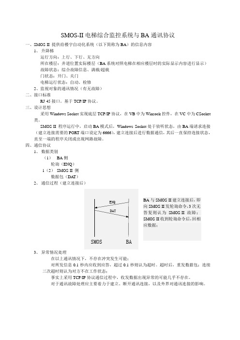
四、通信协议1、 数据类别(1) BA 侧轮询(ENQ )1(2) SMOS-II 侧数据包(DAT )2、 通信过程(建立连接后)3、 异常情况处理在以上通讯情况下,不存在冲突发生可能;对所发信息0.1秒内应收到应答,超过0.1秒则认为超时。
超时后,重发数据包;连续三次超时则认为对方不在工作状态;事实上采用TCP/IP 协议通信过程中,收发数据出现异常的可能几乎不存在。
对于通讯故障处理应主要着力于建立、断开通讯连接,以及外界对通讯连接的影响。
BA 与SMOS-II 建立连接后,即向SMOS-II 发轮询命令,3次无答复则认为SMOS-II 故障;SMOS-II 收到轮询命令后,回相应数据;ENQBA SMOS DAT4、数据格式(1)数据长度(2Bytes )全数据包长度,包括本身长度,高位在前。
(2)控制码(1Byte )表明数据类别。
ENQ 0xE0DAT 0xA0(3)数据内容(3nBytes )仅DAT 数据包含该项内容;DAT 数据包 n 为监视电梯台数;每台电梯数据为3Bytes 。
Gooxi双路高密度服务器准系统SY204-D24RS-G2用户操作手册说明书

双路高密度服务器准系统Rev1.0本手册为双路高密度服务器准系统SY204-D24RS-G2用户操作手册,主要对本产品的特性参数、系统构成、安装方式进行介绍及说明,Gooxi®的此款高密度服务器支持4个双路服务器节点,该系统基于2U四节点24盘位机箱及G2DCN-B主板的整合。
本手册是供专业系统集成商和个人电脑技术人员参考研究,本产品应仅由经验丰富的技术人员进行安装和维护。
手册构架第一章产品介绍本章节提供了系统主要部件的规格并对G2DCN-B主板及2U四节点24盘位机箱的主要特性进行描述。
第二章系统接口介绍本章节提供了系统接口的细节说明,主要包括主板的IO接口和各个连接器、端子及跳线功能和信息。
第三章详细的节点拆装本章提供了G2DCN-B主板上的处理器、内存、扩展卡安装及说明,安装或拆除处理器、内存、扩展卡和散热器的注意事项,可参考本章节内容。
第四章准系统安装及维护本章提供了本高密度服务器上的各节点的安装及维护说明。
第五章系统上架安装本章描述使用SY204-D24RS-G2高密度服务器准系统上架的必需步骤及注意事项。
版权说明©深圳市国鑫恒宇科技有限公司保留所有权利。
本用户手册包括但不限于其所包含的所有信息都受到著作权法的保护,未经深圳市国鑫恒宇科技有限公司(以下简称“国鑫”)许可,不得有任何仿照、复制、摘抄、转发行等行为或为其他利用。
免责声明国鑫是以“现状”提供本用户手册,在法律的允许范围内,不提供任何明示或暗示的担保及保证,包括但不限于商业畅销性、特定目的适用性、未侵害任何他人权利及任何使用本用户手册或无法使用本用户手册的保证,且国鑫对因使用本用户手册而获取的结果或通过本用户手册所获得的任何信息的准确性或可靠性不提供担保及保证。
由于产品版本升级或其他原因,本用户手册内容会不定期进行更新。
除非另有约定,本用户手册仅作为使用指导,用户应自行承担使用本用户手册的所有风险。
商标声明Gooxi是深圳市国鑫恒宇科技有限公司的商标。
BC2900通信协议操作说明
BC2900通信协议操作说明附录 A 通信本分析仪提供四种通信协议,根据外部计算机上安装的数据管理软件可接收的样本编号位数进行匹配。
若可接收的样本编号上限为8位或10位,应选择8ID或10ID通信协议;若可接收的样本编号上限为15位,应选择15ID或15ID+2通信协议。
8ID和10ID通信协议差异在于,10ID 通信协议支持样本编号上限为10位,而8ID支持样本编号上限为8位,除此之外,协议其他部分还存在一些差异,具体差异内容将在后续章节进行介绍。
15ID和15ID+2通信协议差异在于,15ID+2通信协议支持传输P-LCR参数,而15ID 通信协议不支持,除此之外,协议其他部分完全兼容,用户可以根据自己的需求选择相应的通信协议进行通信操作。
迈瑞公司授权人员安装分析仪时,会根据用户配置的数据管理软件选择与之匹配的通信协议。
如需调整分析仪的通信协议,请与迈瑞公司售后服务部联系。
计数界面右上角通信状态标志处于动画状态,表示通信正在进行。
BC-3000 Plus 通过RS-232 串行口,将样本数据和质控数据传送给外部计算机,通信可在样本分析结束后自动完成或由命令选项操作完成。
本章对通信参数的设置、RS-232 串行口连线方式、数据通信格式进行了介绍,为软件工程师编写通信程序提供详细资料,方便用户进行通信操作。
A.1分析仪和计算机的连接BC-3000 Plus 采用DB9连接器与外部计算机连接,DB9连接器针脚安排如图D-1所示。
各引脚说明:DCD:载波检测R XD:接收数据TXD:发送数据D TR:数据终端就绪G ND:信号地D SR:数据设备就绪R TS:请求发送C TS:清除发送R I:振铃指示BC-3000 Plus 通过串口2 和外部计算机通信(最大通信距离小于12米),需要接DB9连接器中的2、3、5 三根线来实现。
A.28ID通信协议和10ID通信协议A.2.1通信数据格式A.2.2通信说明编码[EN0x05Q]0x02[STX][EO0x04T]0x1A[EOF][ET0x03X][AC0x06K][NA0x15CK]"A" 0x41"B" 0x42"C" 0x43"#" 0x30-0x39"*" 0x2AA.2.3编程方法如果“握手”选项设置为“关”,BC-3000 Plus 将数据传送给外部计算机,不对外部计算机的回送信号进行响应。
usxgmii接口标准

usxgmii接口标准USXGMII(10G SerDes External Interface)是一种用于高速数据通信的接口标准,可以提供最高达10Gbps的数据传输速度。
它是由IEEE 802.3工作组制定的标准,旨在满足现代高带宽需求的应用。
USXGMII接口标准的主要目的是提供一个由物理层和数据链路层共同协作的接口规范,以实现高速数据传输。
它通常被用于千兆以太网或其他高速通信标准中,能够支持多种不同的应用场景。
USXGMII接口通过使用多个数据通道以及相应的控制信号,实现数据的传输和接收。
USXGMII接口标准的特点之一是它的高数据传输速度。
以千兆以太网为例,传统的千兆以太网使用MII(介质选择接口)和GMII(千兆介质选择接口)接口,其传输速度限制在1Gbps。
而USXGMII接口则可以提供高达10Gbps的数据传输速度,为现代高带宽应用提供了更高的性能。
此外,USXGMII接口标准还具有较低的功耗和复杂度。
由于其高速数据传输的特性,USXGMII接口在相对较低的功耗下可以实现更高的数据吞吐量。
同时,USXGMII接口本身的设计也相对简单,降低了实现的复杂性和成本,提高了应用的可扩展性和可组装性。
USXGMII接口标准是一个灵活且可定制的标准。
它提供了多种不同的通道配置选项,以适应不同的应用需求。
用户可以根据具体场景选择合适的通道配置,从而平衡数据传输速度、设计复杂度和成本等因素。
总的来说,USXGMII接口标准是一种用于高速数据通信的接口标准,具有高速数据传输、低功耗、低复杂度和灵活性等特点。
它为现代高带宽应用提供了更高的性能和可靠性。
随着数据传输需求的不断增加,USXGMII接口标准将在各种领域中得到广泛应用。
麦格纳电子设备公司XR系列2U程序直流电源说明书

XR 系列2U 程控直流电源 • 可靠电流馈电式功率处理工艺概述XR系列的设计旨在实现可靠性高,功率密度行业领先的2U(3.5英寸高)机架式程控电源的各种功率等级产品,包括:2 kW、4 kW、6 kW、8 kW以及10 kW。
XR系列的特点在于实现了麦格纳电子设备公司产品中最大的电压范围(5Vdc至10,000Vdc),并使用了标志性的电流馈电式功率处理来提供强劲的功率转换能力。
此外,高精度编程和监控级别确保了电源测量的一致性,消除了对外部功率计的需求。
主要特性• 高精度测量• 主从式操作功能• 远地感应• 37-pin外部模拟量I/O接口• RS232接口• 可选配以太网接口和GPIB接口• 0-10V外部模拟输入• 可编程设置保护限值• 快速瞬态响应• 远程接口软件• NI LabVIEW和IVI驱动器• 联锁功能迅速切断输入• 在美国设计和制造可用选项• 高转换速率输出(+HS)• IEEE-488 GPIB通信(+GPIB)• LXI TCP/IP以太网通信(+LXI)• 增强冲击震动标准(+RUG)1标准型号规定纹波。
对于具有高转换速率输出(+HS)的型号,纹波更高。
详情请参考选项页。
第 10 页麦格纳电子设备公司第 11 页数据表 (4.2.0)MagnaDC 程控直流电源规格交流输入隔离±2500 Vac,对地最大输入电压通过 RoHS 认证是(8.89 x 48.26 x 60.96 cm)GPIB: IEEE-488注:参数如有更改,恕不另行通知。
输入电压规格为两线间规格。
第 12 页麦格纳电子设备公司XR 系列2U 程控直流电源 • 可靠电流馈电式功率处理工艺产品图前面板Models with Output Voltage Rating ≤1000 Vdc onlyRefer to “DC Output Bus Connections”3/8-16 Threaded Insert, Qty (2)High Voltage Mating Cable Provided直流输出总线直流输出总线直流输出总线高压输出电缆包含于额定电压大于2,000 Vdc的型号RS232 (JS3)37-PIN EXTERNAL USER I/O (JS1)IEEE-488 GPIB (JS4)TCP/IP ETHERNET (JS5)RS232 (JS3)37-PIN EXTERNAL USER I/O (JS1)LAN RST背面IEEE-488 GPIB (+GPIB) 选项背面LXI TCP/IP 以太网 (+LXI) 选项第 13 页数据表 (4.2.0)MagnaDC 程控直流电源1电源开关:在未接通输出时接通控制电路4通过集成机械接触器接通和断开总电源5用无级旋钮设定电压和电流8REM SEN远地感应:远地感应启用 INT CTL内部:前面板启动/停止/启用清除 EXT CTL外部:外部启动/停止/启用清除 ROTARY旋转:前面板旋钮输入 EXT PGM外部:外部模拟电压电流控制 REMOTE远程:远程计算机控制2POWER电源:显示电源接通 STANDBY待机:待机状态7诊断警报 LOC:联锁 PGL:外部输入电压超限 THL:超高温条件 OVT过压跳闸:过压保护跳闸 OCT过流跳闸:过流保护跳闸6仪表显示输出电压/电流、电压/电流设定点、过压/过流跳闸3功能键MENU菜单:选择功能 ITEM项目:选择功能内的项目 V/I DIS V/I显示器:显示电压和电流设置 TRIP DIS跳闸显示器:显示过压/过流跳闸设置 CLEAR清除:清除设置或重置故障 ENTER进入:选择项目C 版前面板–空白前面板概述(15) XR系列电源,选配+CAB3选件第 4 页麦格纳电子设备公司在美国设计和制造均通过内部制造和粉末涂层。
电梯标准通讯协议

电梯标准通讯协议
电梯通讯协议主要有以下三种:
1. RSL协议:由主控板(LCB_II)和最多60个RS节点(也就是RS5、RS18等电路板)组成。
在每个时钟周期中总线可传输11个数据位。
2. 分机地址:分机地址为00H至7FH,由终端的拔码开关设定。
主机需要查询分机的数据,可以发送相应的数据帧。
3. 主机软件编写注意事项:
* 任意两个字节的发送需要有一定的间隔时间(一般为1ms 左右,这个只是一个参考值,要视实际情况及线路的长短而定,实际最佳值可以在调试中确定)以保证可靠接收。
* 终端分机从接收到指令包到数据输出完毕需要一定的转换时间。
当通信速率为9600bps时,对每台分机的查询操作需要占用50ms的时间段。
* 在多机通信中特别需要注意保持数据的完整性与可靠性,对于来自线路的各种干扰均能够可靠地处理。
以上内容仅供参考,具体协议的名称、内容、解释可能因实际不同而有所差异,建议咨询电梯公司或专业技术人员,获取更准确的信息。
UM220-III N 通讯协议

目录1概述 (1)1.1消息的格式 (1)1.2校验和 (1)1.3数据类型 (2)2消息定义 (3)2.1Common Message (3)2.1.1PDTINFO (3)2.1.2RESET (3)2.1.3OK (4)2.1.4FAIL (4)2.2Config Message (4)2.2.1CFGPRT (4)2.2.2CFGMSG (5)2.2.3CFGNAV (6)2.2.4CFGTM (7)2.2.5CFGTP (8)2.2.6CFGEM (9)2.2.7CFGNMEA (9)2.2.8CFGSYS (10)2.2.9CFGSAVE (10)2.2.10CFGLOAD (11)2.2.11CFGCLR (11)2.3NMEA Message (11)2.3.1GGA (11)2.3.2GLL (12)2.3.3GSA (13)2.3.4GSV (14)2.3.5RMC (15)2.3.6VTG (16)2.3.7ZDA (16)2.3.8GST (17)2.4Navigation Result Message (18)2.4.1NAVPOS (18)2.4.2NAVVEL (18)2.4.3NAVTIME (19)2.5Misc Message (19)3默认配置 (21)3.1串口设置(CFGPRT) (21)3.2消息设置(CFGMSG) (21)3.3定位配置(CFGNAV) (21)3.4授时配置(CFGTP) (21)3.5外部触发事件配置(CFGEM) (22)3.6NMEA配置(CFGNMEA) (22)3.7卫星系统配置(CFGSYS) (22)1概述1.1消息的格式在Unicore协议中,输入和输出的语句被统称为消息。
每条消息均为全ASCII字符组成的字符串。
消息的基本格式为:$MSGNAME,data1,data2,data3,…[*CC]\r\n所有的消息都以'$'(0x24)开始,后面紧跟着的是消息名。
- 1、下载文档前请自行甄别文档内容的完整性,平台不提供额外的编辑、内容补充、找答案等附加服务。
- 2、"仅部分预览"的文档,不可在线预览部分如存在完整性等问题,可反馈申请退款(可完整预览的文档不适用该条件!)。
- 3、如文档侵犯您的权益,请联系客服反馈,我们会尽快为您处理(人工客服工作时间:9:00-18:30)。
1M-Bus Protocol (2)1.1Single character (2)1.2Short frame: (2)1.2.1SND_NKE (2)1.2.2REQ_UD2 (3)1.3Long frame master to slave (3)1.3.1Application reset (3)1.3.2Set primary M-bus address (4)1.3.3Set identification number (4)1.3.4Select meter by secondary address (5)1.3.5Set billing date (5)1.3.6Set date and time (6)1.4User-specific frames: (7)1.4.1Deletion of maximum values (for information only) (7)1.4.2Init Tariff register (7)1.4.3Backup (for information only) (9)1.4.4Update calculations (for information only) (9)1.5Long frame slave to master (10)1.5.1REQ_UD2 (10)2Summary of M-bus data types (12)2.1.132-bit Type A (12)2.1.2Type B (12)2.1.3Type C (12)2.1.4Type D (12)2.1.5Type F (12)2.1.6Type G (12)1 M-Bus ProtocolAll bytes transmitted over the M-bus and the optical interface have the format 8E1:1 8 1 1Start bit Data bits Parity bit (even) Stop bitFor communication three different telegram types are used. These are:1. Single character h’E5 (only used by slave )2. Short frame (only used by master)3. Long frame (used by both master and slave)1.1 Single characterThe single character h’E5 (CON_ACK) is only used by the meter. It serves as an acknowledgement of the reception of a valid frame (it does not say anything about whether the command was accepted and executed or not!)1.2 Short frame:10 C A csum 16Short frames always consist of 5 bytes.They are initiated by the master.There are two different frames: SND_NKE and REQ_UD2…C“ Command…A“ Address“csum” Low byte of the sum of “C” and “A”1.2.1 SND_NKEDeselection of a meter after selection by its secondary address.Short frame identifier 10…C“ 40…A“ adrsChecksum csumStop byte 16Acknowledged by h’E5.1.2.2 REQ_UD2Request for a data frameShort frame identifier 10…C“ 5b or 7b…A“ adrsChecksum csumStop byte 16Acknowledged by a long frame.1.3 Long frame master to slave68 len len 68 C A CI userdata csum 16 …C“ Command…A“ Address…CI“ Control information“len” Total amount of bytes in user data + 3 (“C”, “A”, …CI“).Maximum length is FFh (max. 252 data bytes)“csum” Low byte of the sum of er data“, “C” ,“A” and (I)1.3.1 Application resetLong frame identifier 68Length bytes 03, 03Long frame identifier 68…C“ byte 53 or 73…A“ byte adrs…CI“ byte 50Checksum csumStop byte 16This deselects the device (secondary addressing).Frame length: 9 bytesAcknowledged by h’E5.1.3.2 Set primary M-bus addressLong frame identifier 68Length bytes 06, 06Long frame identifier 68…C“ byte 53 or 73…A“ byte adrs…CI“ byte 5101, 7ASet primary M-bus addresscommandNew primary address new_adrsChecksum csumStop byte 16…new_adrs“ for setting a new M-bus addressFrame length: 12 bytesAcknowledged by h’E5.1.3.3 Set identification numberLong frame identifier 68Length bytes 09, 09Long frame identifier 68…C“ byte 53 or 73…A“ byte adrs…CI“ byte 51Set identification number command 0C, 794-byte type A identification number ID low… ID highChecksum csumStop byte 16ID low… ID high for setting a new identification numberFrame length: 15 bytesAcknowledged by h’E5.Generally, the identification number and the serial number have the same value.1.3.4 Select meter by secondary addressLong frame identifier 68Length bytes 0B, 0BLong frame identifier 68…C“ byte 53 or 73…A“ byte FD…CI“ byte 524-byte type A serial number S low… S high2-byte manufacturer code Man low… Man highMeter version number VerMedium code MedChecksum csumStop byte 16The placeholder … h’F“ can be used at any decimal place of the serial number.The placeholder “h’FF” can be used for “medium code“, …meter version number“ and …manufacturer code“.Frame length: 17 bytesAcknowledged by h’E5, if the secondary address is correct.1.3.5 Set billing dateLong frame identifier 68Length bytes 08, 08Long frame identifier 68…C“ byte 53 or 73…A“ byte adrs…CI“ byte 51Set billing date command 02, EC, 004-byte …type G“ billing date d low… d highChecksum csumStop byte 16Frame length: 14 bytesThe validity of the date is not checked.Acknowledged by h’E5.1.3.6 Set date and timeLong frame identifier 68Length bytes 0A, 0ALong frame identifier 68…C“ byte 53 or 73…A“ byte adrs…CI“ byte 51DIF 04VIF EDVIFE 004-byte …type F“ date and time d low… d highChecksum csumStop byte 16Frame length: 16 bytesAcknowledged by h’E5.The validity of the date and time is not checked.Years <=80 corresponds to 2000 – 2080Note: Changing the date may influence the billing period and monthly values.1.4 User-specific frames:1.4.1 Deletion of maximum values (for information only)The registers …maximum flow“ and …maximum power“ are reset to 0. The frame is not an M-bus standard.Long frame identifier 68Length bytes 08, 08Long frame identifier 68…C“ byte 53 or 73…A“ byte adrs…CI“ byte 51Manufacturer-specific data 0FNot used 00, 00Not used 00Max value deleted 07Checksum csumStop byte 16Frame length: 14 bytesAcknowledged by h’E5.1.4.2 Init Tariff registerLong frame identifier 68Length bytes 0B, 0BLong frame identifier 68…C“ byte 53 or 73…A“ byte Adrs…CI“ byte 51Manufacturer-specific data 0FPassword PW low, PW highRbRegister 0: Register 11: Register 2User Byte 1BTariff register option 0: not defined1: Time period from / until2: Power greater than orequal to3: Power less than or equalto4: Flow greater than or equalto5: Flow less than or equal to6: Forward flow temperaturegreater than or equal to7: Forward flow temperatureless than or equal to8: Return flow temperaturegreater than or equal to9: Return flow temperatureless than or equal to10: Temperature differencegreater than or equal to11: Temperature differenceless than or equal toTariff register threshold 1: Field 1: Set <from> timein 10 min. intervals; Field 2:Set <until> time in 10 min.intervals; (e.g. 09:10 ->9*6+1 = 55)2: Set threshold value (unit:see set display unit)3: Set threshold value (unit:see set display unit)4: Set threshold value (unit:see set display unit)5: Set threshold value (unit:see set display unit)6: Set threshold value (unit:0,00 °C, e.g. 70,00 °C ->7000)7: Set threshold value (unit:0,00 °C, e.g. 50,00 °C ->5000)8: Set threshold value (unit:0,00 °C, e.g. 25,00 °C ->2500)9: Set threshold value (unit:0,00 °C, e.g. 15,00 °C ->1500)10: Set threshold value (unit:0,00 K, e.g. 10,00 K ->1000)11: Set threshold value (unit:0,00 K, e.g. -5,00 K -> -500) Checksum CsumStop Byte 161.4.3 Backup (for information only)The current consumption values are stored in the EEPROM.The frame is not an M-bus standard.Long frame identifier 68Length bytes 08, 08Long frame identifier 68…C“ byte 53 or 73…A“ byte adrs…CI“ byte 51Manufacturer-specific data 0FNot used 00, 00Not used 00Backup 08Checksum csumStop byte 16Frame length: 14 bytesAcknowledged by h’E5.1.4.4 Update calculations (for information only)Processes not yet processed volume pulses, including temperature measurement. The frame is not an M-bus standard.Long frame identifier 68Length 08, 08Long frame identifier 68…C“ 53 or 73…A“ adrs…CI“ 51Manufacturer-specific data 0FNot used 00, 00Not used 00Update calculations 09Checksum csumStop byte 16Frame length: 14 bytesAcknowledged by h’E5.1.5 Long frame slave to master1.5.1 REQ_UD2Response to a REQ_UD2 command.Long frame identifier 68Length bytes len, lenLong frame identifier 68…C“ byte 08…A“ byte adrs…CI“ byte 724-byte type A identification number i low… i high2-byte manufacturer code Man low… Man highMeter version number VerMedium code MedAccess number AccStatus StaSignature 00, 00Data bytes read b1…b nChecksum csumStop byte 16Frame length: 160 to 175 bytesAmount of data bytes: 139 to 154The “access number” is the amount of data frames sent by the meter (M-bus and optocoupler). The value is incremented before being sent.The “status” is generally “00h”. In case of an error in the meter the current error code will be sent.Definition of the data bytes:Length Function DIF(+E) VIF(+E) Data type6 Serial number 04 78 32-bit type A 6 Current date and time 04 6D 32-bit type F 6 or7 Total volume (current) 04 13 (0.001 m³)15 (0.1 m³)FB,22 (0.1 gal)FB,21 (0.1 ft³)32-bit type C6 or7 Total volume (lastbilling date) 44 13 (0.001 m³)15 (0.1 m³)FB,22 (0.1 gal)FB,21 (0.1 ft³)32-bit type C7 or 8 Total volume (lastmonth) 84,01 13 (0.001 m³)15 (0.1 m³)FB,22 (0.1 gal)FB,21 (0.1 ft³)32-bit type C6 or7 Total heat energy 04 05 (0.1 kWh) 32-bit type C(current) 06 (0.001 MWh)FB,00 (0.1 MWh)0E (0.001 GJ)6 or7 Total heat energy(last billing date) 44 05 (0.1 kWh)06 (0.001 MWh)FB,00 (0.1 MWh)0E (0.001 GJ)32-bit type C7 or 8 Total heat energy(last month) 84,01 05 (0.1 kWh)06 (0.001 MWh)FB,00 (0.1 MWh)0E (0.001 GJ)32-bit type C7 or 8 Total cooling energy(current) 84,10 05 (0.1 kWh)06 (0.001 MWh)FB,00 (0.1 MWh)0E (0.001 GJ)32-bit type C7 or 8 Total cooling energy(last billing date) C4,10 05 (0.1 kWh)06 (0.001 MWh)FB,00 (0.1 MWh)0E (0.001 GJ)32-bit type C7 or 8 Total cooling energy(last month) 84,11 05 (0.1 kWh)06 (0.001 MWh)FB,00 (0.1 MWh)0E (0.001 GJ)32-bit type C4 Last billing date 42 6C 16-bit type G 4 Next billing date 02 6C 16-bit type G7 or 8 Tariff register 1(current) 84,20 05 (0.1 kWh)06 (0.001 MWh)07 (0.01 MWh)FB,00 (0.1 MWh)0E (0.001 GJ)20 (1 s)32-bit Typ C7 or 8 Tariff register 2(current) 84,30 05 (0.1 kWh)06 (0.001 MWh)07 (0.01 MWh)FB,00 (0.1 MWh)0E (0.001 GJ)20 (1 s)32-bit Typ C6 or7 Current flow 04 39 (0.01 l/h) 32-bit type B 6 or 7 Maximum flow 14 39 (0.01 l/h) 32-bit type B 6 or 7 Current power 04 2A (0.1 W) 32-bit type B 6 or 7 Maximum power 14 2A (0.1 W) 32-bit type B 4 Forward flowtemperature02 5B (1 °C) 16-bit type B4 Return flowtemperature02 5F (1 °C) 16-bit type B6 Temperaturedifference04 61 (0.01 °C) 32-bit type B 4 Days in operation 02 23 16-bit type C 4 Error code 01 FD,17 8-bit type D2 Summary of M-bus data types2.1.1 32-bit Type ALS word15 12 11 8 7 4 3 0 3 (nibble 3) 0 3 (nibble 2) 0 3 (nibble 1) 0 3 (nibble 0) 0 MS word15 12 11 8 7 4 3 0 3 (nibble 7) 0 3 (nibble 6) 0 3 (nibble 5) 0 3 (nibble 4) 0 Used for the serial number of the heat meter.2.1.2 Type BRepresents a two’s binary integer with sign.2.1.3 Type CRepresents an binary integer without sign.2.1.4 Type DRepresents a bit field.2.1.5 Type FLS word15 12 11 8 7 4 3 0 SU not used 4 hours 0 IV n.u. 5 minutes 0 MS word15 12 11 8 7 4 3 0 6 year (part) 3 3 month 0 2 year (part) 0 4 day 0 Application: date / time2.1.6 Type G15 12 11 8 7 4 3 0 6 year (part) 3 3 month 0 2 year (part) 0 4 day 0 Application: date / time。