电动绞车_机械类毕业设计开题报告
绞车设计开题报告
绞车设计开题报告绞车设计开题报告一、引言绞车是一种常见的起重设备,广泛应用于工业、建筑、冶金等领域。
本次设计的目标是设计一种高效、安全、可靠的绞车,以满足现代工程项目的需求。
二、绞车的基本原理绞车是通过电动机或液压系统驱动,通过绞盘上的绳索或链条来提升或牵引重物。
其基本原理是利用电动机或液压系统的动力将能量转化为机械能,通过绞盘的旋转来实现物体的升降或移动。
三、绞车设计的要求1. 承载能力:绞车需要能够承载不同重量的物体,并保证其安全运行。
2. 运行速度:绞车需要具备快速升降物体的能力,以提高工作效率。
3. 控制系统:绞车需要配备可靠的控制系统,以实现对运行速度、方向等参数的精确控制。
4. 安全性:绞车需要具备安全保护装置,如限位器、过载保护等,以避免意外事故的发生。
四、绞车的结构设计1. 电动机或液压系统:选择适合承载能力的电动机或液压系统,并考虑其功率、效率和可靠性。
2. 绞盘:设计合适尺寸和材质的绞盘,以满足承载能力和使用寿命的要求。
3. 绳索或链条:选择适合承载能力的绳索或链条,并考虑其耐磨性和抗拉强度。
4. 控制系统:设计可靠的控制系统,包括电气控制和液压控制,以满足对运行速度和方向的精确控制。
5. 安全保护装置:设计合适的限位器、过载保护装置等,以确保绞车的安全运行。
五、绞车设计的挑战和解决方案1. 承载能力挑战:通过合理选择电动机或液压系统,并结合优化设计绞盘和绳索或链条,以提高绞车的承载能力。
2. 运行速度挑战:通过优化电动机或液压系统的功率和传动装置的设计,以提高绞车的运行速度。
3. 控制系统挑战:采用先进的电气控制和液压控制技术,结合合适的传感器和执行器,以实现对运行速度和方向的精确控制。
4. 安全性挑战:设计可靠的限位器、过载保护装置等,结合合适的安全操作规程和培训,以确保绞车的安全运行。
六、绞车设计的意义和应用前景1. 意义:设计一种高效、安全、可靠的绞车,可以提高工程项目的施工效率,降低劳动强度,保障工人的安全。
机械课题开题报告范文

机械课题开题报告范文尊敬的指导老师:您好!我打算在这里向您提交我的机械课题开题报告。
经过深思熟虑和仔细研究,我选择了“柔性机器人在工业应用中的优化设计与控制研究”作为我的机械课题。
一、选题背景和意义:在当前快速发展的工业领域中,机器人的应用日益广泛。
而柔性机器人作为机器人技术的重要分支之一,具有结构紧凑、自身柔软、高度灵活的特点,能够适应复杂、狭小和危险环境的需求。
然而,现有柔性机器人在工业应用中仍存在一些问题,例如控制精度不高、效率低下、鲁棒性不足等。
鉴于此,本课题旨在通过优化设计和控制算法的研究,解决柔性机器人在工业应用中的问题,提高其性能和适应性,推动柔性机器人技术的发展和应用。
二、研究目标:本课题的主要研究目标包括以下几点:1.分析柔性机器人的结构和特点,深入理解其工作原理和运动控制机制。
2.研究柔性机器人的优化设计方法,通过结构优化和材料选择等手段,提高其性能和精度。
3.设计适用于工业应用的柔性机器人的控制算法,实现精确控制和高效率工作。
4.开展仿真实验和实际应用测试,验证优化设计和控制算法的有效性和实用性。
三、研究方法和步骤:为了达到上述研究目标,本课题将采取以下方法和步骤:1.资料收集和文献综述:收集和整理关于柔性机器人结构、控制算法以及优化设计方法的相关资料和文献,深入了解柔性机器人的研究现状和发展趋势。
2.理论分析和建模:基于柔性机器人的结构和特点,进行理论分析,建立柔性机器人的数学模型和控制模型,定量描述其动力学和运动规律。
3.优化设计方法研究:借鉴现有的优化设计方法,结合柔性机器人的特点,提出适用于柔性机器人的优化设计方法,包括结构优化和材料选择等,以提高柔性机器人的性能和精度。
4.控制算法设计与实现:根据理论分析和建模结果,设计适用于工业应用的柔性机器人控制算法,包括轨迹跟踪、力控制和碰撞检测等,以实现柔性机器人的精确控制和高效率工作。
5.仿真实验和实际应用测试:借助仿真软件和实验平台,对优化设计方法和控制算法进行仿真实验,并进行实际应用测试,验证其有效性和实用性。
绞车变频调速系统设计开题报告
绞车变频调速系统设计开题报告.txt 选题的目的和意义变频调速技术的基本原理是根据电机转速与工作电源输入频率成正比的关系: n =60 f(1-s/p,(式中 n、f、s、p 分别表示转速、输入电源的频率、电机转差率、电机磁极对数;通过改变电动机工作电源频率达到改变电机转速的目的。
变频调速技术已深入我们生活的每个角落,变频调速系统的控制方式包括 V/F、矢量控制(VC、直接转矩控制(DTC等。
V/F 控制主要应用在低成本、性能要求较低的场合;而矢量控制的引入,则开始了变频调速系统在高性能场合的应用。
绞车(winch又称为卷扬机,是用卷筒缠绕钢丝绳或链条以提升或牵引重物的轻小型起重设备。
绞车的驱动一般是采用手动、电动或者液压方式,但在大型化和自动化程度越来越高的形势下,电动的优势更明显,因而使用也越来越广泛。
电动驱动中主要是采用交流变频调速系统对绞车进行驱动。
通过变频调速系统对绞车进行控制其优势在于: 1、结构紧凑、体积小、移动方便、可节省大量运输和开拓费用; 2、安全防爆,适用含有煤尘,瓦斯或其它易燃易爆气体的场所; 3、变频绞车是以全数字变频调速为基础,以矢量控制技术为核心,使异步电机的调速性能可以与直流电机相媲美。
表现在低频转矩大、调速平滑、调速范围广、精度高、节能明显等; 4、采用 PLC 控制系统,使绞车的控制性能和安全性能更加完善; 5、操作简单、运行安全稳定、故障率低、基本免维护。
绞车是工业生产过程中一种常见的机械,具有悠久的发展历史和比较成熟的设计制造技术。
随着绞车制造技术的不断提高、加工材料的不断改进以及电子控制技术的不断发展,绞车在动力、节能和安全性等方面取得了很大的进步。
目前,绞车正被广泛地运用于矿山、港口、工厂、建筑和海洋等诸多领域。
我国的绞车其调速原理经历了电阻调速,液压调速、变频调速及行星差动调速等几次大的改进,目前国产绞车所采用的调速装置主要有两种类型:一是液压传动调速装置(液压调速,其产品形式即为现有的液压绞车;二是电控调速装置(变频调控,其产品形式即为现有的传统 JT 系列绞车。
机电毕业论文开题报告模板

机电毕业论文开题报告模板机电毕业论文开题报告模板一、选题的依据及意义:随着内燃机高功率、高速化发展,人们对其性能指标的要求更高,这给配气机构的设计以及制造工艺增加了难度。
目前广泛采用的是气门-凸轮式配气机构,它具有保证气缸密封性的优点。
配气机构系统研究内容归纳起来主要有两个方面,一方面是零部件的设计,包括凸型线,气门摇臂机构的设计,气门弹簧及气门等零部件的设计,其中又以凸轮型线的设计尤为关键,这是因为凸轮作为整个机构的原动件,它直接控制整个机构的运动。
另一方面是机构的动力学问题,而对于机构动力性能的研究,又主要集中在气门的运动规律上。
国外对配气机构的振动模型、摩擦及配气相位和可变气门正时等的研究有一些报道。
国内也在致力于研究更精确的气门振动模型、凸轮挺柱副的动力润滑、非对称凸轮型线以及凸轮型线的拟合等问题,主要表现在以下几个方面:(1)设计了许多性能优良的凸轮型线;(2)配气机构由刚性设计发展为弹性设计;(3)由孤立研究凸轮设计发展到配气机构系统设计。
2)多气门技术。
配气机构的最新发展是改善燃料经济性,其关键在于如何提供更多的新鲜空气,多气门内燃机很早就已经出现了,但仅用于赛车,目的是减轻排气门的热负荷和机械负荷,但并未能在内燃机制造业得到推广。
促使多气门内燃机产量迅速提高的原因在于自动控制技术的快速发展和生产工艺水平的不断提高,多气门配气方案能保证内燃机在整个负荷和速度范围内形成最佳混合气,并适时适度送入气缸。
多气门内燃机不仅可以提高内燃机功率,还可以降低燃油消耗,减少排污。
据分析4气门内燃机燃油消耗比2气门内燃机燃油消耗低6%~8%。
(1)计算软件简介可以进行配气机构动力学和运动学分析、齿轮系的运动分析等。
(2)YC4108柴油机的性能指标为气缸数-缸径×冲程:4-108mm×115mm 连杆长度:L=152mm燃烧形式:直接喷射润滑方式:压力循环飞溅复合式电机停止方式:燃油控制系统怠速:600rpm 最大空转:3000rpm冷起动温度:-25℃ 排气温度:。
电动绞车的传动装置(机械课程设计)

电动绞车的传动装置(机械课程设计)————————————————————————————————作者:————————————————————————————————日期:南京航空航天大学机械设计课程设计任务书题目:电动绞车的传动装置姓名学号学院专业 08机械工程及其自动化班级指导教师设计完成日期2010 年12 月6 日目录1.设计任务书 (3)2.传动方案的拟定及电动机的选择 (4)3.传动装置的运动和动力参数计算 (6)4.传动零件的设计计算 (7)5.轴的计算 (12)6.键连接的选择和计算 (16)7.滚动轴承的选择和计算 (18)8.联轴器的选择 (20)9.润滑与密封的选择 (21)10.设计小结 (22)11.参考资料 (23)一.机械设计课程设计任务书学生:谭进波学号:050810731 班级:0508107 设计完成日期2010年12月5日任课老师:谢正宇指导老师:郭勤涛设计题目:电动绞车的传动装置传动简图原始数据:参数卷轴筒所需扭矩T(N.m)运输带速度V(m/s)卷筒直径D(mm)数据1500 0.62 400工作条件:轻微振动载荷;双向传动;室外工作。
使用期限:10年;2班制;长期使用。
生产批量:成批。
工作机速度允许误差: +5%设计工作量:1,减速器装配图1张(A0);2,零件工作图两张(A2,减速器输出轴和输出轴上大齿轮)3,设计说明书1份。
二.传动方案的拟定及电动机的选择1.选择电动机类型按工作要求和条件,选择三相笼型异步电动机,封闭式结构,电压380V,Y型。
2.选择电动机容量工作机所需功率P w=T∗w1000,而P d=P wηa,因此 P d=T∗w1000ηa。
由电动机至滚筒的传动总效率为 ηa=η12∗η24∗η32∗η4,式中η1,η2,η3,η4分别是联轴器,轴承,齿轮,滚筒的传动效率。
参照表2-5取η1=0.99,η2=0.99(球轴承),η3= 0.97(8级精度),η4=0.96则ηa=0.96∗0.994∗0.972∗0.992= 0.85所以 P d=T∗w1000ηa=1500∗2∗0.621000∗0.4∗0.85=5.47kw3.确定电动机转速卷筒轴转速n=60∗1000∗vπ∗D=60∗1000∗0.62π∗400=29.6 r/min按表2-5推荐的传动比合理范围,两级齿轮减速器传动比为9~36,,因此电动机转速的可能范围为266.4~1065.6 r/min 。
新型绞车毕业设计(论文)开题报告

[7]UG.5三维制图软件
5、工作方案分析及进度计划(工作思路)
本少齿差式行星齿轮传动绞车,是采用少齿差式行星齿轮传动原理,即用一对尺寸完全相同的行星齿轮同时与两个内齿轮相啮合,两个内齿轮存在一定的齿数差。这种绞车与老式绞车相比结构更合理,简单,制造工艺性好,传动效率高,使用寿命长且成本低.
随着回采工作面综合机械化的迅速发展 ,要求许多小型辅助设备具有体积更小、重量更轻、维修更加方便等优点 ,以适应不同的生产环境。对井下普遍应用的回柱绞车尤其要求如此。目前 ,回采工作面放顶支架的回收主要依靠回柱绞车来完成 ,这种绞车传动原理简单 ,操作容易 ,而且维修也很方便。其不足之处在于 :一般体积都比较大 ,也比较笨重 ,在巷道内运输、移动时较为不便。因此 ,需要在保证该绞车原有各项功能的基础上 ,进一步减小尺寸、降低重量 ,使之充分发挥小型矿用绞车搬运轻便、操作灵活、修配方便等优点 ,以适应更复杂的工作环境.
第二阶段:找资料设计绞车各零部件
第三阶段:画机械零件图
第四阶段:整理资料,综合毕业论文
第五阶段:定稿打印,提交毕业设计论文
第六阶段:论文Biblioteka 辩报告人:年月日指导教师意见
指导教师:
年月日
开题报告应根据教师下发的设计(论文)任务书,在指导教师的指导下由学生独立撰写。
国外矿用小绞车规格比较多,适用不同场合,我国矿用小绞车的规格少,品种型号多而乱,也较繁杂,没有统一标准。从工作机构上分,国外有单筒、双筒及摩擦式三种,我国只有单筒一种型式。从原动力上分,国外有电动的、风动的及液压驱动,我国只有电动的和少量风动的。
例如回柱绞车的薄弱环节是球面蜗轮副传动,回柱绞车的主传动均采用了蜗轮副传动,这是因为蜗轮副传动比大,又具有自锁性,故其传动效率较低,一般只有0. 4~0.45,回柱绞车的总传动效率更低。回绳速度慢,所有的回柱纹车回绳速度和工作牵引速度相同.不论绞车用于回柱放顶,还是搬运设备,工作效率太低。随着采煤机械化的发展,综采设备的频繁搬迁,又由于回柱绞车搬运,工作时间长占用人工多,因此这类绞车均应设置快速回绳。
JWB-50无极绳绞车的设计-开题报告
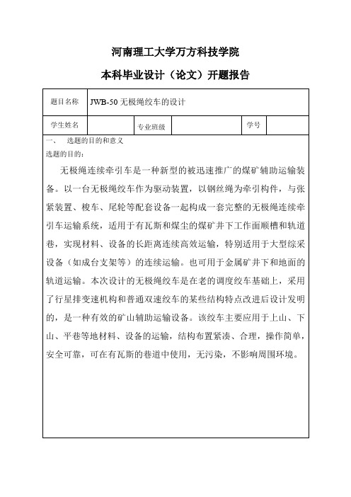
河南理工大学万方科技学院本科毕业设计(论文)开题报告题目名称JWB-50无极绳绞车的设计学生姓名专业班级学号一、选题的目的和意义选题的目的:无极绳连续牵引车是一种新型的被迅速推广的煤矿辅助运输装备。
以一台无极绳绞车作为驱动装置,以钢丝绳为牵引构件,与张紧装置、梭车、尾轮等配套设备一起构成一套完整的无极绳连续牵引车运输系统,适用于有瓦斯和煤尘的煤矿井下工作面顺槽和轨道巷,实现材料、设备的长距离连续高效运输,特别适用于大型综采设备(如成台支架等)的连续运输。
也可用于金属矿井下和地面的轨道运输。
本次设计的无极绳绞车是在老的调度绞车基础上,采用了行星排变速机构和普通双速绞车的某些结构特点改进后设计发明的,是一种有效的矿山辅助运输设备。
该绞车主要应用于上山、下山、平巷等地材料、设备的运输,结构布置紧凑、合理,操作简单,安全可靠,可在有瓦斯的巷道中使用,无污染,不影响周围环境。
选题的意义:1) 培养理论联系实际的设计思想,通过课题研究回顾、总结大学三年所学。
在以后工作中,能更快速地提高专业技术;2) 综合性地运用几年内所学知识去分析、解决一个问题。
使自己的实践动手、动笔能力得到锻炼;3) 为工作时候的产品开发、改进打下基础;4)掌握文献检索、资料查询的基本方法以及获取新知识的能力二、国内外研究综述:限矩型液力偶合器是以液体为工作介质的一种非刚性联轴器,又称液力联轴器。
主要由主动部分和被动部分组成。
主动部分包括后辅室、前半联轴节、后半连轴节、弹性块、泵轮和外壳。
从动部分主要包括轴和涡轮等。
主动部分与原动机联接,被动部分与工作机联接。
液力偶合器的泵轮和涡轮组成一个可使液体循环流动的密闭工作腔,泵轮装在输入轴上,涡轮装在输出轴上。
动力机(内燃机、电动机等)带动输入轴旋转时,液体被离心式泵轮甩出。
这种高速液体进入涡轮后即推动涡轮旋转,将从泵轮获得的能量传递给输出轴。
最后液体返回泵轮,形成周而复始的流动。
液力偶合器靠液体与泵轮、涡轮的叶片相互作用产生动量矩的变化来传递扭矩。
电动绞车传动装置的设计
毕业设计(论文)(说明书)题目:电动绞车传动装置的设计姓名:贺子杰编号:理工大学年月日理工大学毕业设计(论文)任务书贺子杰专业机械设计与制造任务下达日期年月日设计(论文)开始日期年月日设计(论文)完成日期年月 1 日设计(论文)题目:A·编制设计B·设计专题(毕业论文)指导教师系(部)主任年月日理工大学毕业设计(论文)答辩委员会记录系专业,学生于年月日进行了毕业设计(论文)答辩。
设计题目:专题(论文)题目:指导老师:答辩委员会根据学生提交的毕业设计(论文)材料,根据学生答辩情况,经答辩委员会讨论评定,给予学生毕业设计(论文)成绩为。
答辩委员会人,出席人答辩委员会主任(签字):答辩委员会副主任(签字):答辩委员会委员:,,,,,,理工大学毕业设计(论文)评语第页共页毕业设计(论文)及答辩评语:摘要这篇毕业设计的论文主要阐述的是一套系统的关于圆柱齿轮减速器的设计方法。
在论文中,首先,阐述了圆柱齿轮减速器的设计原理和理论计算。
然后按照设计准则和设计理论设计了圆柱齿轮减速器。
接着对减速器的部件组成进行了尺寸计算和校核。
该设计代表了减速器设计的一般过程。
对其他的减速器设计工作也有一定的价值。
在这次设计中进一步培养了工程设计的独立能力,树立正确的设计思想掌握常用的机械零件,机械传动装置和简单机械设计的方法和步骤,要求综合的考虑使用经济工艺等方面的要求。
齿轮传动是现代机械中应用最广的一种传动形式。
它的主要优点是:①瞬时传动比恒定、工作平稳、传动准确可靠,可传递空间任意两轴之间的运动和动力;②适用的功率和速度围广;③传动效率高,η=0.92-0.98;④工作可靠、使用寿命长;⑤外轮廓尺寸小、结构紧凑。
通过这一次设计可以初步掌握一般简单机械的一套完整的设计及方法,构成减速器的通用零部件。
这次毕业设计主要介绍了减速器的类型作用及构成等,全方位的运用所学过知识。
确定合理的设计方案。
关键词:减速器轴承齿轮机械传动论文类型:设计报告ABSTRACTThis graduation thesis on the design of the system is a ring on the cylinder wheel gear reducer design method.In the paper, first of all, the cylinder wheel gear reducer on the design principle and the theoretical calculation. Then in accordance with the design criteria and design theory designed the cylinder wheel gear reducer .Then the ponents of the reducer to the size of the calculation and verification. The design represents the reducer general design process.On the other reducer in the design work will have value.Further educated in this time design independent ability that engineering design, set up the right design thought controls the in mon use machine spare parts ,the machine spread to move the device with the simple machine design of method with step ,the consideration that request synthesize usage the request of economic craft etc .Wheel gear's spreading to move is a the most wide kind of the application spreads to move a form in the modern machine. Its main advantage BE:The①spreads to move to settle, work than in amoment steady, spread to move accurate credibility, can deliver space arbitrarily sport and the motive of the of two stalks;Power and speed scope;②applies are wide;③spreads to move an efficiency high, η=0.92-0.98; ④work is dependable, service life long; ⑤Outline size outside the is small, structure tightly packed.Pass thisdesign can then the first step controls general simple a set of plete designs step and methods of the machine.This time graduate the design to introduce the type function of the deceleration machine and constitute the etc. Primarily , made use of all-directionsly learned the knowledge .Make sure the reasonable design project.Key Word:Reduction gear, Bearing ,Gear ,Mechanical driveDissertation Type:Report on Designs目录第1章传动装置的总体设计21.1选择电动机型号21.2传动比的分配31.3计算传动装置的运动和动力参数3第2章传动零件的设计42.1锥齿轮传动的设计42.1.1选择齿轮材料、齿轮精度级、齿数42.1.2强度计算52.1.3精确校核齿根弯曲疲劳强度62.1.4锥齿轮传动的几何尺寸如下表所示:72.2高速级圆柱齿轮的基本参数及强度计算82.2.1选取高速级齿轮精度级、类型、材料、齿数及螺旋角82.2.2按齿面接触强度设计82.2.3按齿根弯曲强度设计102.2.4几何尺寸计算112.2.5校核结果112.2.6齿轮结构尺寸的设计122.3低速级圆柱齿轮的基本参数及强度计算132.3.1选取低速级齿轮精度级、类型、材料、齿数及螺旋角132.3.2按齿面接触强度设计132.3.3按齿根弯曲强度设计152.3.4几何尺寸计算162.3.5校核结果162.3.6齿轮结构尺寸的设计16第3章轴的设计与计算173.1轴的材料选择和初定轴的最小直径173.2减速器装配草图的设计183.3轴的结构设计183.3.1高速轴的结构设计193.3.2中间轴的结构设计203.3.3低速轴的结构设计20第4章轴的校核214.1轴的力学模型建立如下图所示214.2计算轴上的作用力224.3计算支反力224.4绘转矩、弯矩图234.5弯矩合成强度校核25第5章键的选择与校核255.1中间轴上的键255.2高速轴上的键255.3低速轴上的键26第6章滚动轴承的选择与校核276.1.滚动轴承的选择276.2滚动轴承的校核(这里以中间轴为例)27第7章联轴器的选择28第8章箱体结构及附件的设计298.1箱体结构的设计298.2箱体尺寸的设计298.3附件的设计31第9章润滑与密封的设计32第10章设计总结33参考文献33致34设计题目:电动绞车传动装置的设计传动方案的拟定数据要求:钢绳的拽引力F=12K N钢绳的工作速度:V=0.38m/s绞盘直径D=300m m工作条件:工作环境较差,结构紧凑,使用寿命10年(每年按300天计算),两班工作制,连续单向运转,工作时有轻微冲击,小批量生产,钢绳工作速度允许误差±0.5%图一电动绞车传动装置示意图1—电动机2—锥齿轮3—齿轮减速器4—联轴器5—滚筒6—绞车链12第1章 传动装置的总体设计1.1选择电动机型号1.选择电动机的类型按工作要求选用型全封闭笼Y 型三相异步电动机。
- 1、下载文档前请自行甄别文档内容的完整性,平台不提供额外的编辑、内容补充、找答案等附加服务。
- 2、"仅部分预览"的文档,不可在线预览部分如存在完整性等问题,可反馈申请退款(可完整预览的文档不适用该条件!)。
- 3、如文档侵犯您的权益,请联系客服反馈,我们会尽快为您处理(人工客服工作时间:9:00-18:30)。
本科毕业(设计)论文开题报告学生姓名赵孝威学号07B********指导教师吴元生系别机电工程系专业机械设计制造及其自动化交稿日期教务处制一、开题报告二、阅读文献目录三、文献综述注意:学生阅读文献后,必须写出3000字左右的综述,作为开题内容之一。
(可增页)电动绞车简介:电动绞车广泛用于工作繁重和所需牵引力较大的场所。
单卷筒电动绞车的电动机经减速机带动卷筒,电动机与减速器输入轴之间装有制动器。
为适应提升、牵引和回转等作业的需要,还有双卷筒和多卷筒装置的绞车。
一般额定载荷低于10T的绞车可以设计成电动绞车结构组成:卷筒,减速机,制动器,电气系统。
1、卷筒设计的基本原则在右面的图表中,弹簧卷筒“水平放线”和“垂直放线”的两种应用方式都有表示。
横向电缆安装:- 可以向1或2个方向出线。
- 电缆在连续平面上拖拽或用间隔小于1m的支撑将电缆撑离地面。
-安装高度从电缆拖拽平面到卷筒中心不超过1m。
- 不考虑电缆转向- 运行速度为:10米/分钟--60米/分钟-最大加速度可达0.3 m/s²垂直电缆安装:- 卷筒安装在顶端- 电缆出现方向垂直向下-运行速度为:10米/分钟--40米/分钟-最大加速度可达0.3 m/s²-自由下垂的电缆长度L0不考虑。
三、卷筒和电缆的选择如果应用在如下极端特殊的环境,强烈建议跟我们联系:-运行速度小于10 m/min- 强烈震动- 应用在海上,盐或者腐蚀性空气中-温度低于-15 °C - 急弯路径- 需要强制导向(见下栏)如果安装了强制导向器必须保证导向器与卷筒之间的距离为卷筒宽度的6倍。
弹簧卷筒必须安装在电缆可以自由放出和卷起,并且没有障碍物的位置上。
强制导向和尺寸太小的导向轮在任何情况下都不允许的。
四、文献翻译图1.三相电动机的图解模型用q–d框架参考转换建立了一个三相步进电机的数学模型。
下面给出了三相绕组电压方程v a = Ria+ L*dia/dt − M*dib/dt − M*dic/dt + dλpma/dt ,v b = Rib+ L*dib/dt − M*dia/dt − M*dic/dt + dλpmb/dt ,v c = Ric+ L*dic/dt − M*dia/dt − M*dib/dt + dλpmc/dt , (1)其中R和L分别是相绕组的电阻和感应线圈,并且M是相绕组之间的互感线圈。
λpma , λpmband λpmc是应归于永磁体的相的磁通,且可以假定为转子位置的正弦函数如下λpma = λ1sin(Nθ),λpmb = λ1sin(Nθ− 2/3),λpmc = λ1sin(Nθ - 2/3), (2)其中N是转子齿数。
本文中强调的非线性由上述方程所代表,即磁通是转子位置的非线性函数。
使用Q ,d转换,将参考框架由固定相轴变换成随转子移动的轴(参见图2)。
矩阵从a,b,c 框架转换成q,d框架变换被给出了[8](3)例如,给出了q,d参考里的电压(4)在a,b,c参考中,只有两个变量是独立的(ia + ib+ ic= 0),因此,上面提到的由三个变量转化为两个变量是允许的。
在电压方程(1)中应用上述转换,在q,d框架中获得转换后的电压方程为v q = Riq+ L1*diq/dt + NL1idω + Nλ1ω,v d = Rid+ L1*did/dt − NL1iqω, (5)注意:请将外文文献原文复印件附在后面。
Oscillation, Instability and Control of Stepper MotorsLIYU CAO and HOWARD M. SCHWARTZDepartment of Systems and Computer Engineering, Carleton University, 1125 Colonel By Drive,Ottawa, ON K1S 5B6, Canada(Received: 18 February 1998; accepted: 1 December 1998)Abstract. A novel approach to analyzing instability in permanent-magnet stepper motors is presented. It is shown that there are two kinds of unstable phenomena in this kind ofmotor: mid-frequency oscillation and high-frequency instability. Nonlinear bifurcation theory is used to illustrate the relationship between localinstability and midfrequencyoscillatory motion. A novel analysis is presented to analyze the loss of synchronism phenomenon, which is identified as high-frequency instability. The concepts of separatrices and attractors in phase-space are used to derive a quantity to evaluate the high-frequency instability. By using this quantity one can easily estimate the stability for high supply frequencies. Furthermore, a stabilization method is presented. A generalized approach to analyze the stabilization problem based on feedback theory is given. It is shown that the mid-frequency stabilityand the high-frequency stability can be improved by state feedback. Keywords: Stepper motors, instability, nonlinearity, state feedback.1. IntroductionStepper motors are electromagnetic incremental-motion devices which convert digital pulse inputs to analog angle outputs. Their inherent stepping ability allows for accurate position control without feedback. That is, they can track any step position in open-loop mode, consequently no feedback is needed to implement position control. Stepper motors deliver higher peak torque per unit weight than DC motors; in addition, they are brushless machines and therefore require less maintenance. All of these properties have made stepper motors a very attractive selection in many position and speed control systems, such as in computer hard disk drivers and printers, XY-tables, robot manipulators, etc.Although stepper motors have many salient properties, they suffer from an oscillation or unstable phenomenon. This phenomenon severely restricts their open-loop dynamic performance and applicable area where high speed operation is needed. The oscillation usually occurs at stepping rates lower than 1000 pulse/s, and has been recognized as a mid-frequency instability or local instability [1], or a dynamic instability [2]. In addition, there is another kind of unstable phenomenon in stepper motors, that is, the motors usually lose synchronism at higher stepping rates, even though load torque is less than their pull-out torque. This phenomenon is identified as high-frequency instability in this paper, becauseit appears at much higher frequencies than the frequencies at which themid-frequency oscillation occurs. The high-frequency instability has not been recognized as widely as mid-frequency instability, and there is not yet a method to evaluate it.Mid-frequency oscillation has been recognized widely for a very long time, however, a complete understanding of it has not been well established. This can be attributed to the nonlinearity that dominates the oscillation phenomenon and is quite difficult to deal with.384 L. Cao and H. M. SchwartzMost researchers have analyzed it based on a linearized model [1]. Although in many cases, this kind of treatments is valid or useful, a treatment based on nonlinear theory is needed in order to give a better description on this complex phenomenon. For example, based on a linearized model one can only see that the motors turn to be locally unstable at some supplyfrequencies, which does not give much insight into the observed oscillatory phenomenon. In fact, the oscillation cannot be assessed unless one uses nonlinear theory.Therefore, it is significant to use developed mathematical theory on nonlinear dynamics to handle the oscillation or instability. It is worth noting that Taft and Gauthier [3], and Taft and Harned [4] used mathematical concepts such as limit cycles and separatrices in the analysis of oscillatory and unstable phenomena, and obtained some very instructive insights into the socalled loss of synchronous phenomenon. Nevertheless, there is still a lack of a comprehensive mathematical analysis in this kind of studies. In this paper a novel mathematical analysis is developed to analyze the oscillations and instability in stepper motors.The first part of this paper discusses the stability analysis of stepper motors. It is shown that the mid-frequency oscillation can be characterized as a bifurcation phenomenon (Hopf bifurcation) of nonlinear systems. One of contributions of this paper is to relate the midfrequency oscillation to Hopf bifurcation, thereby, the existence of the oscillation is provedtheoretically by Hopf theory. High-frequency instability is also discussed in detail, and a novel quantity is introduced to evaluate high-frequency stability. This quantity is very easyto calculate, and can be used as a criteria to predict the onset of thehigh-frequency instability. Experimental results on a real motor show the efficiency of this analytical tool.The second part of this paper discusses stabilizing control of stepper motors through feedback. Several authors have shown that by modulating the supply frequency [5], the midfrequencyinstability can be improved. In particular, Pickup and Russell [6, 7] have presented a detailed analysis on the frequency modulation method. In their analysis, Jacobi series was used to solve a ordinary differential equation, and a set of nonlinear algebraic equations had to be solved numerically. In addition, their analysis is undertaken for a two-phase motor, and therefore, their conclusions cannot applied directly to our situation, where a three-phase motor will be considered. Here, we give a more elegant analysis for stabilizing stepper motors, where no complex mathematical manipulation is needed. In this analysis, a d–q model of stepper motors is used. Because two-phase motors and three-phase motors have the same q–d model and therefore, the analysis is valid for both two-phase and three-phase motors. Up to date, it is only recognized that the modulation method is needed to suppress the midfrequency oscillation. In this paper, it is shown that this method is not only valid to improve mid-frequency stability, but also effective to improve high-frequency stability.2. Dynamic Model of Stepper MotorsThe stepper motor considered in this paper consists of a salient stator with two-phase or threephase windings, and a permanent-magnet rotor. A simplified schematic of a three-phase motor with one pole-pair is shown in Figure 1. The stepper motor is usually fed by a voltage-source inverter, which is controlled by a sequence of pulses and produces square-wave voltages. Thismotor operates essentially on the same principle as that of synchronous motors.One of major operating manner for stepper motors is that supplying voltage is kept constant and frequencyof pulses is changed at a very wide range. Under this operating condition, oscillation and instability problems usually arise.Figure 1. Schematic model of a three-phase stepper motor.A mathematical model for a three-phase stepper motor is established using q–d framereference transformation. The voltage equations for three-phase windings are given byv a = Ria+ L*dia/dt − M*dib/dt − M*dic/dt + dλpma/dt ,v b = Rib+ L*dib/dt − M*dia/dt − M*dic/dt + dλpmb/dt ,v c = Ric+ L*dic/dt − M*dia/dt − M*dib/dt + dλpmc/dt ,where R and L are the resistance and inductance of the phase windings, and M is the mutual inductance between the phase windings. _pm a, _pm b and _pm c are the flux-linkages of thephases due to the permanent magnet, and can be assumed to be sinusoid functions of rotor position _ as followλpma = λ1sin(Nθ),λpmb = λ1sin(Nθ− 2/3),λpmc = λ1sin(Nθ - 2/3),where N is number of rotor teeth. The nonlinearity emphasized in this paper is represented by the above equations, that is, the flux-linkages are nonlinear functions of the rotor position.By using the q; d transformation, the frame of reference is changed from the fixed phase axes to the axes moving with the rotor (refer to Figure 2). Transformation matrix from the a; b; c frame to the q; d frame is given by [8]For example, voltages in the q; d reference are given byIn the a; b; c reference, only two variables are independent (ia C ib C ic D 0); therefore, the above transformation from three variables to two variables is allowable. Applying the abovetransformation to the voltage equations (1), the transferred voltage equation in the q; d frame can be obtained asv q = Riq+ L1*diq/dt + NL1idω + Nλ1ω,v d =Rid+ L1*did/dt − NL1iqω, (5)Figure 2. a, b, c and d, q reference frame.where L1 D L C M, and ! is the speed of the rotor.It can be shown that the motor’s torque has the following form [2]T = 3/2Nλ1i qThe equation of motion of the rotor is written asJ*dω/dt = 3/2*Nλ1iq− Bfω– Tl ,where Bf is the coefficient of viscous friction, and Tl represents load torque, which is assumed to be a constant in this paper.In order to constitute the complete state equation of the motor, we need another state variable that represents the position of the rotor. For this purpose the so called load angle _ [8] is usually used, which satisfies the following equationDδ/dt = ω−ω,where !0 is steady-state speed of the motor. Equations (5), (7), and (8) constitute the statespace model of the motor, for which the input variables are the voltages vq and vd. As mentioned before, stepper motors are fed by an inverter, whose output voltages are not sinusoidal but instead are square waves. However, because the non-sinusoidal voltages do not change the oscillation feature and instability very much if compared to the sinusoidal case (as will be shown in Section 3, the oscillation is due to the nonlinearity of the motor), for the purposes of this paper we can assume the supply voltages are sinusoidal. Under this assumption, we can get vq and vd as followsv q = Vmcos(Nδ) ,v d = Vmsin(Nδ) ,where Vm is the maximum of the sine wave. With the above equation, we have changed the input voltages from a function of time to a function of state, and in this way we can represent the dynamics of the motor by a autonomous system, as shown below. This will simplify the mathematical analysis.From Equations (5), (7), and (8), the state-space model of the motor can be written in a matrix form as followsẊ = F(X,u) = AX + Fn(X) + Bu , (10) where X D T iq id ! _U T , u D T!1 Tl U T is defined as the input, and !1 D N!0 is the supply frequency. The input matrix B is defined byThe matrix A is the linear part of F._/, and is given byFn.X/ represents the nonlinear part of F._/, and is given byThe input term u is independent of time, and therefore Equation (10) is autonomous.There are three parameters in F.X;u/, they are the supply frequency !1, the supply voltage magnitude Vm and the load torque Tl . These parameters govern the behaviour of the stepper motor. In practice, stepper motors are usually driven in such a way that the supply frequency !1 is changed by the command pulse to control the motor’s speed, while the supply voltage is kept constant. Therefore, we shall investigate the effect of parameter !1.3. Bifurcation and Mid-Frequency OscillationBy setting ! D !0, the equilibria of Equation (10) are given asand ' is its phase angle defined byL1/R) . (16)φ = arctan(ω1Equations (12) and (13) indicate that multiple equilibria exist, which means that these equilibria can never be globally stable. One can see that there are two groups of equilibria as shown in Equations (12) and (13). The first group representedby Equation (12) corresponds to the real operating conditions of the motor. The second group represented by Equation (13) is always unstable and does not relate to the real operating conditions. In the following, we will concentrate on the equilibria represented by Equation (12).。