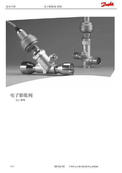
ETS电子膨胀阀
ETS6技术手册(12P)

5
技术手册 阀门选型 (续)
过冷度 ΔTsc 修正系数
6
电子膨胀阀,ETS 6
步骤 1 确定过冷度 ΔTsc 修正系数。在修正系数列表 中(如下所示),当过冷度为 10 K 时,R407C 对应的修正系数为 1.14。
过冷度 ΔTsc 修正系数
ΔTsc
0
0°F
R22
1.00
R410A
1.00
R407C
8.95 9.75 10.13 10.35 10.79 11.06 8.59 9.41
5 11.21 11.84 12.11 12.25 12.44 12.41
9.61 10.26 10.57 10.75 11.09 11.28
9.27 9.96
0 11.88 12.38 12.58 12.67 12.77 12.66 10.11 10.65 10.90 11.04 11.30 11.42
3
技术手册
电子膨胀阀,ETS 6
阀门规格
型号
最大
单包装 订货代码
工业包装 订货代码 (每箱 100 件)
流口 [mm]
R22
额定能力 [kW]
连接(焊接)
R134a
R404A
R407C
R410A
A [mm]
B [mm]
阀 管 型 式
MWP MOPD 反向 压力
[bar] [bar] [bar]
ETS 6 - 10 034G5005
HCF、HCFC(例如:R410A, R407C, R404A, R134a, R22) 适用于热泵应用的双向流运行
2
技术手册 结构与工作原理
电子膨胀阀,ETS 6
电子膨胀阀原理、调试和故障维修

电子膨胀阀原理、调试和故障维修
电子膨胀阀是一种新型的节流装置,为制冷系统的智能化控制提供了条件,具有调节范围大、动作迅速灵敏、调节精密、稳定可靠等优点。
它可以根据接受到的脉冲信号控制膨胀阀开度,保证适量的供液量和合适的过热度。
电子膨胀阀系统由电子膨胀阀阀体ETS、控制器EKC312、驱动器EKD316、压力
传感器AKS33和温度传感器AKS111组成。
控制器是该系统
的核心器件,类似于人体大脑,可以接受压力传感器和温度传感器的信号,通过内部计算发出脉冲信号来控制电子膨胀阀的开度,保证系统供液量和过热度。
安装电子膨胀阀时应注意电机应位于正上方,与阀体轴心垂直(±15°),以防止电机的润滑油沉积在阀底部,影响系统和阀体的性能。
在阀入口处安装100~120目的过滤网,以防
止异物进入。
焊接时,阀体部分的温度不能超过120℃,用水
冷却时,阀体内不能进水。
常见故障检修包括电子膨胀阀的阀门处于全闭状态和开机后电子膨胀阀内有噪音。
对于阀门处于全闭状态的故障,可以
进行复位操作来确保阀体处于开的状态,以调节膨胀阀的流量。
对于电子膨胀阀内有噪音的故障,可以检查是否存在异物或杂质,或者检查电子膨胀阀是否松动或损坏。
中央空调电子膨胀阀操作说明 中文版样本

数据通讯时的参数
数据通讯模块的安装按
面板上的发光二极管
面板上的LED在相应延时激活时发光。
最上方的LED指示阀的开度增大。
第二个LED指示阀的开度减小。
当调节过程中发生错误时,所有的
参数的保存
操作示例
订货
型号功能产品代码EKC 312 过热度控制器084B7250 EKA 173 数据通讯接口模块(附
件,FTT10模式)
084B7092 EKA 175 数据通讯接口模块(附
件,RS 485模式)
084B7093
EKA 174 数据通讯接口模块(附
件,RS 485模式)084B7124
内部和外部开关交互作用以及其他动作。
用一个压力信号。
负荷定义过热度
基于定义的过热度曲线设定。
该曲线由三个值确
自适应过热度
基于蒸发器的负荷,通过查找MSS。
电子膨胀阀控制原理

电子膨胀阀控制原理电子膨胀阀是一种用于制冷系统中的控制装置,它的作用是通过控制制冷剂的流量来调节蒸发器的温度和压力,从而实现对制冷系统的精确控制。
电子膨胀阀控制原理是制冷技术领域的重要内容,下面将详细介绍电子膨胀阀的控制原理及其工作过程。
电子膨胀阀是一种利用电子技术控制的智能膨胀阀,它通过传感器感知蒸发器的温度和压力,并根据设定的控制策略来调节膨胀阀的开度,从而实现对制冷系统的精确控制。
电子膨胀阀通常由传感器、控制器和执行机构三部分组成,传感器用于感知蒸发器的温度和压力,控制器根据传感器的信号来计算出膨胀阀的开度,执行机构则根据控制器的指令来调节膨胀阀的开度。
电子膨胀阀的控制原理主要包括两个方面,一是根据蒸发器的温度和压力来确定膨胀阀的开度,二是根据制冷系统的工况来调节膨胀阀的开度。
在实际工作中,电子膨胀阀通过传感器感知蒸发器的温度和压力,控制器根据传感器的信号来计算出膨胀阀的开度,执行机构则根据控制器的指令来调节膨胀阀的开度,从而实现对制冷系统的精确控制。
电子膨胀阀的工作过程可以简单描述为,当蒸发器的温度和压力升高时,传感器会感知到这一变化并将信号传递给控制器,控制器根据传感器的信号来计算出膨胀阀的开度,执行机构则根据控制器的指令来调节膨胀阀的开度,使制冷剂的流量增加,从而降低蒸发器的温度和压力;反之,当蒸发器的温度和压力降低时,传感器同样会感知到这一变化并将信号传递给控制器,控制器根据传感器的信号来计算出膨胀阀的开度,执行机构则根据控制器的指令来调节膨胀阀的开度,使制冷剂的流量减小,从而提高蒸发器的温度和压力。
总的来说,电子膨胀阀的控制原理是通过传感器感知蒸发器的温度和压力,控制器根据传感器的信号来计算出膨胀阀的开度,执行机构则根据控制器的指令来调节膨胀阀的开度,从而实现对制冷系统的精确控制。
电子膨胀阀在制冷技术领域有着广泛的应用,它的出现极大地提高了制冷系统的控制精度和稳定性,为制冷行业的发展带来了新的机遇和挑战。
丹佛斯小型电子膨胀阀ETS6 技术资料英文
MAKING MODERN LIVING POSSIBLEDanfoss A/S (AC-MCI sw) 2013-10 DKRCC.PD.VD1.D3.02 / 520H7937Data sheetElectronic expansion valves Type ETS 6The range of electronic expansion valves are based on many years of experience.ETS 6 secure reliability and provide a precise solutions for ex p ansion and flow control in a wide range of refrigeration and air conditioning systems.Compact and lightweight. The current range is available with a wide capacity range, and can be used with all common fluorinated refrigerants. Bi-flow operation is also possible for heat pump systems.The valve operation is by means of a uni-polar motor, which can be controlled by a number of controllers from Danfoss or third party vendors.With an EKD 316 and EIM 336 (current drivers) and an AKS sensor, an accuracy better than +/-0.5 K can be obtained.Please contact Danfoss for more details.FeaturesOptimized energy efficiency of the system. Precision flow control with high resolution. Compact and lightweight. Energy saving design.Proven know-how and high reliability. Wide range for all common refrigerants. Bi-flow for heat pump applications.2DKRCC.PD.VD1.D3.02 / 520H7937Danfoss A/S (AC-MCI sw) 2013-10Data sheetElectronic Expansion Valves, type ETS 6Design/functionThe ETS 6 electronic expansion valves open and close to regulate refrigerant flow by means of a screw, whose rotating motion is transformed into linear motion. This occurs by the rotation of a magnet-needle valve assembly whichmoves when electrical signals are applied to the surrounding coil.Within the coil structure, there are different winding configurations, and the polarities arechanged by the electrical signals applied. By application of the appropriate combination of signals, in the form of pulses, the coil forces the rotor of the valve to move in a stepwise fashion.Application of multiple pulses will make the valve mechanism to move through a series of steps in the chosen direction, in order to set the valve with the required opening degree.CoilPermanent magnet motorNeedle valveValve bodyCross section diagram of ETS 6 series* Refers to refrigerant flow in cooling modeOutlet (A*)Inlet (B*)Technical dataFig. 1ApprovalsComplies with: EC PED 97/23/EC a3P3UL, RoHS and CQCRoHSData sheet Electronic Expansion Valves, type ETS 6Danfoss A/S (AC-MCI sw) 2013-10 DKRCC.PD.VD1.D3.02 / 520H79373Electrical wiringStepper motor switch sequenceThe illustration shows the JST XHP-6 connetor. The coil with JST XHP-5 is identical except that it does not have an unused pinCT=38°C, ET=5°C, SC=0°C, SH=0°C*Please contact Danfoss if higher maximum reverse pressure valve is required.1) Max. Reverse Pressure = Pressure as which the valve can still close tightly in reverse direction (from A to B see fig. 1).Valve ordering4 DKRCC.PD.VD1.D3.02 / 520H7937 Danfoss A/S (AC-MCI sw) 2013-10Data sheetElectronic Expansion Valves, type ETS 6For optimum performance, it is important to correct the evaporator capacity. In order toselect the correct size of ETS 6 you will need the following information:Refrigerant: HCFC or HFCEvaporator capacity Q e in kW or TR Evaporating temperature t e in °C or °F Condenser temperature t c in °C or °F Subcooling Δt sub in K or °F ExampleWhen selecting the valve it may be necessary to apply a correction factor to the actual evaporator capacity. This correction factor is required when system conditions are different than tableconditions. Selection also depends on having an acceptable pressure drop across the valve. In the selection table, the pressure drop in the liquid line is assumed to be zero. The following example illustrates correct selection of the valve.Refrigerant: R407CEvaporator capacity: Q e = 10 kW (2.84TR)Condensing temperature: t c = 40°C (104 °F) Evaporating temperature: t e = +10°C (50°F) Subcooling Δt sub = 10 KApplication exampleValve SelectionHeat pump components in typical system.1. Compressor.2. Controller.3. Four-way valve.4. Temperature sensor.5. Pressure transmitter.6. Cartridge pressure control.7. Evaporator.8. Condenser.9. Temperature sensor.10. Electronic expansion valve.11. Sight glass.12. Liquid line filter drier.Data sheetElectronic Expansion Valves, type ETS 6Danfoss A/S (AC-MCI sw) 2013-10 DKRCC.PD.VD1.D3.02 / 520H7937 5Step 1Determine the correction factor for subcooling Δt sub . From the correction factor table (see below) a subcooling of 10 K, R407C corresponds to a factor of 1.14.Correction factors for subcooling Δt sub .Step 2Corrected evaporator capacity isQ e (Corrected) = 10 kW/1.14 = 8.8 kW (2.5 TR)Step 3Select the appropriate capacity table, R407C, and choose the column for condensing temperature of t c = 40°C (104°F) and evaporating temperature of t e = 10°C (50°F) which will provide anequivalent or greater capacity of 8.8 kW (2.5 TR).ETS 6-18 provides 10.35 kW (2.94 TR), which is the proper selection for this example.Step 4Choose ETS 6-18:Single pack code no. 034G5026 I-pack code no. 034G5024Valve Selection (continued)Rated Capacity (kW)Correction factors for subcooling Δt subThe evaporator capacities used must be corrected if subcooling deviates from 0 K.The corrected capacity can be obtained bydividing the required evaporator capacity by the correction factor below. Selections can then bemade from the tables above.6 DKRCC.PD.VD1.D3.02 / 520H7937 Danfoss A/S (AC-MCI sw) 2013-10Data sheetElectronic Expansion Valves, type ETS 6Rated Capacity (kW)Rated Capacity (kW)Data sheetElectronic Expansion Valves, type ETS 6Danfoss A/S (AC-MCI sw) 2013-10 DKRCC.PD.VD1.D3.02 / 520H79377Rated Capacity (kW)Rated Capacity (kW)Data sheetElectronic Expansion Valves, type ETS 6Rated Capacity (kW)8 DKRCC.PD.VD1.D3.02 / 520H7937 Danfoss A/S (AC-MCI sw) 2013-10Data sheetElectronic Expansion Valves, type ETS 6Danfoss A/S (AC-MCI sw) 2013-10 DKRCC.PD.VD1.D3.02 / 520H79379Rated Capacity (TR)Rated Capacity (TR)10 DKRCC.PD.VD1.D3.02 / 520H7937 Danfoss A/S (AC-MCI sw) 2013-10Data sheetElectronic Expansion Valves, type ETS 6Rated Capacity (TR)Rated Capacity (TR)Data sheetElectronic Expansion Valves, type ETS 6Danfoss A/S (AC-MCI sw) 2013-10 DKRCC.PD.VD1.D3.02 / 520H793711Rated Capacity (TR)Rated Capacity (TR)Data sheet Electronic Expansion Valves, type ETS 6 Capacities, continuedConditionsR410 AT e: 5°CT c: 38°C Subcooling: 0°C Superheat: 0°C(B to A ref. drawing page 1)12 DKRCC.PD.VD1.D3.02 / 520H7937 Danfoss A/S (AC-MCI sw) 2013-10Data sheetElectronic Expansion Valves, type ETS 6Danfoss A/S (AC-MCI sw) 2013-10 DKRCC.PD.VD1.D3.02 / 520H7937 13DimensionsETS 6-10ETS 6-14ETS 6-25ETS 6-32ETS 6-40All dimensions in mmETS 6-18All dimensions in mmRelated Danfoss ProductsWeight: 0.16 kg (complete)。
ETS 电子膨胀阀
-9-
RD1TA402 丹佛斯 A/S (RC-CMS/MWA),03-2005
技术手册
制冷量 范围-40oF ~50oF
电子膨胀阀 ETS
额定制冷量 TR 阀两端压力降 Δp[psig]
US 单位制
过冷度修正系数 :当过冷度偏离 4K 时,蒸发器制冷量必须进行修正。修正制冷量为所需制冷量除以下表中 的修正系数。根据以上表格选择阀门型号。 注意:过冷度太低,会形成闪发蒸汽。
技术手册
制冷量 范围:-40℃~10℃
电子膨胀阀 ETS
额定制冷量 kW 阀两端压力降 Δp[巴]
SI 单位制
过冷度修正系数 :当过冷度偏离 4K 时,蒸发器制冷量必须进行修正。修正制冷量为所需制冷量除以下表中 的修正系数。根据以上表格选择阀门型号。 注意:过冷度太低,会形成闪发蒸汽。
修正系数
-8-
电机保护
IP67
参数 适用工质 CE 认证 MOPD 最大工作压力(PS/MWP) 制冷温度范围 环境温度 总行程 电机保护
ETS 250/ETS 400 HFC, HCFC 有 33bar(478.6psi) 34bar(493psi) -40℃to10℃(-40F to 50F) -40℃to60℃(-40F to 140F) 17.2mm(0.68in.) IP67
1. 电缆 2. 玻璃封口 3. AST 马达护盖 4. 步进马达 5. 轴承 6. 推杆 7. 填料 8. 活塞 9. 密封垫 10. 阀口
-4-
电子膨胀阀 ETS
线圈1
红
绿
+
-
+
-
-
+
-
+
+
-
ETS 50-400 双极永磁
电子膨胀阀控制系统原理-安装调试——丹弗斯
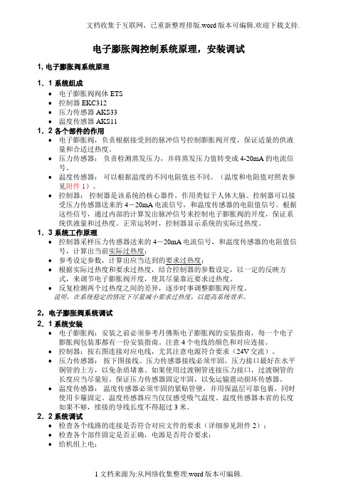
电子膨胀阀控制系统原理,安装调试1, 电子膨胀阀系统原理1.1 系统组成•电子膨胀阀阀体ETS•控制器EKC312•压力传感器AKS33•温度传感器AKS111.2 各个部件的作用•电子膨胀阀,负责根据接受到的脉冲信号控制膨胀阀开度,保证适量的供液量和合适过热度。
•压力传感器:负责检测蒸发压力,并将蒸发压力值转变成4-20mA的电流信号。
•温度传感器:可以根据温度的不同电阻值也不同。
(温度和电阻值对照表参见附件 1)。
•控制器:控制器是该系统的核心器件,作用类似于人体大脑。
控制器可以接受压力传感器送来的4-20mA电流信号,和温度传感器的电阻值信号。
根据这些信号,通过内部的计算发出脉冲信号来控制电子膨胀阀的开度,保证系统供液量和过热度。
正常运转时,控制器显示系统的实际过热度。
1.3 系统工作原理•控制器采样压力传感器送来的4-20mA电流信号,和温度传感器的电阻值信号,计算出当前实际过热度;•参考设定参数,计算出应当达到的要求过热度;•根据实际过热度和要求过热度,结合控制器的参数设定,以一定的反映方式,来调节电子膨胀阀开度,使其尽量靠近要求过热度。
•反复检测两个过热度之间的差异,逐步时事调整膨胀阀开度。
说明,在系统稳定的情况下尽量减小要求过热度,以提高系统效率。
2,电子膨胀阀系统调试2.1系统安装•电子膨胀阀:安装之前必须参考丹佛斯电子膨胀阀的安装指南,每一个电子膨胀阀包装那都有一份安装指南。
注意4个电线的颜色和对应连接。
•控制器:按右图连接对应电线,尤其注意电源符合要求(24V交流)。
•压力传感器:按下图接线。
压力传感器接线必须牢固,压力接口最好在水平铜管的上方,以免杂质堵塞。
如果使用过渡铜管连接压力接口,过渡铜管的长度应当尽量短。
保证压力传感器固定牢固,以免运输震动损坏传感器。
•温度传感器:温度传感器必须牢固的紧贴管壁,并用保温层可靠包裹,同时使用卡篐固定。
温度传感器应当仅仅感受吸气温度。
温度传感器本省的长度如果不够,续接的导线长度不得超过3米。
ETS250-400 安装说明

Max. +60°C (140°F) Min. -40°C (-40°F)
Resistance / Widerstand / résistance électrique / Resistencia / 电阻 Stepper motor type / Schrittmotortype / Type de moteur pas à pas / Tipo de motor a pasos / 步进电机形式
PS / MWP 34 bar (493 psig) * Flow direction for liquid verification using the sight glass ETS 250* ETS 400* KVS 42 (without sight glass)
Application Anwendung Application Aplicación 应用
© Danfoss A/S (AC-MCI/sw), 2014-06
© Danfoss A/S (AC-MCI sw), 2012-07
034R9799
Danfoss 34G68.15
Mounting Einbau Montage Installación 安装
© Danfoss A/S (AC-MCI/sw), 2014-06
DKRCC.PI.VD1.B4.ML / 520H6540
1
034R9799
034R9799
Brazing Löten Soudure Soldadura 焊接
Compatible refrigerants / Kompatibilität / Fluides compatibles / Compatibilidad de refrigerantes / 适用的冷媒 Fluid temperature / Kältemitteltemperaturbereich / Température du fluide / temperatura líquida / 流体温度 Nominal voltage / Nennspannung / Tension nominale / Voltaje nominal / 名义电压 Phase current / Phasenstrom / Phase électrique / Corriente de fase / 相电流 R134a, R404A, R507 R407C, R410A, R22 and other refrigerants -40°C to 65°C (-40°F to 149°F) 12 V DC 100 mA 52 Ω Bipolar / 单级
- 1、下载文档前请自行甄别文档内容的完整性,平台不提供额外的编辑、内容补充、找答案等附加服务。
- 2、"仅部分预览"的文档,不可在线预览部分如存在完整性等问题,可反馈申请退款(可完整预览的文档不适用该条件!)。
- 3、如文档侵犯您的权益,请联系客服反馈,我们会尽快为您处理(人工客服工作时间:9:00-18:30)。
温ŏ传感,
温ŏ传感,/ Pt 1000 ohm
AKS 11
Temp. Range
[℃]
Cable [m]
3.5
-50 +100
5.5
8.5
Code No.
084N0003 084N0006 084N0008
AKS 12
Temp. Range [℃]
-40 +80
Cable [m]
Quantity
• MOP 设ୱ • ࣯୧备य电౧
继电,输ෆ
• 报警
12 REFRIGERATION AND AIR CONDITIONING
丹佛斯控制器特点
ୢਨ
参数设,调试简单ࠇཥ
• ়ر参数ũ可过控,来设
13 REFRIGERATION AND AIR CONDITIONING
丹佛斯控制器特点
33
“
060G2101 060G2105 060G2049 060G2117
40
0 +80 060G2102 060G2106 060G2050 060G2118
55
“
060G2103 060G2107 060G2051 060G2119
Cable G 3/8 A
¼ Flare 060G2062
060G2065
ୢձ
2种过热ŏ控Ϸ܉ • ઞ适应过热ŏ/ඟخ稳态过热ŏ (ෆ厂设) • 负载ୱ义过热ŏ
ཥ业ʻ̩ඟ优ଝ过热ŏ控Ϸ܉
•• TThhrroouugghhSSHHsseeaarrcchhiningg,,rreeffeerreenncceeSSHH vvaalulueettoobbeelolowweerreeddttililllssuuccttioionntteemmpp.. hhaauunnttiningg
压ȇခ温ŏ传感,
ྦྷ号
Danfoss AKS 33
Danfoss AKS 11
IJ码
- 稳ୱ可፷
- PT 1000
ୢ
7 REFRIGERATION AND AIR CONDITIONING
压ȇ传感,
压ȇ传感,
AKS33 (适यस EKC 312, 315 & 316)
Operating Range [bar]
AKS 32R (适यस EKD316)
Operating Range [bar]
Max.
Compensate
Working Pr.
Temp.
[bar]
[C]
-1 12
33
- 30 +40
-1 34
55
0 +80
Connection Plug with 5m cable1)
¼ NPT 060G1037
18
16
13
37
34
27
69.1
62
48.9
ቤተ መጻሕፍቲ ባይዱ128.7
115.4
91.2
349
319
252
556
509
402
R404a 12 25 46.3 86.6 239 381
1) Rated Condition ① Te : 5 ℃ ② Tc : 32 ℃ ③ SC : 4 K
6 REFRIGERATION AND AIR CONDITIONING
-1 9 -1 12 -1 20 -1 34
Max. Compensa
Working te Temp.
Pr. [bar]
[C]
Code No. EN 175301-803, plug pg 9 ¼ NPT G 3/8 A ¼ Flare ¼ NPT
33
- 30 +40 060G2113 060G2111 060G2044
电ઐຠ胀阀 ό馈值
实际输ෆ
传感,
Controller
ETS Sensors
3 REFRIGERATION AND AIR CONDITIONING
控,驱动,介绍
ྦྷ号 订货IJ码
ୢ
EKC312 EKC315 EKC316A EKD316 EKA164A
084B7250 084B7086 084B7088 084B8040 084B8563
1) Plug is not included in AKS 32R
REFRIGERATION AND AIR CONDITIONING
Code No.
G 3/8 A
¼ Flare
060G1038 060G1036
060G0090
060G1034
3/8 Solder 060G3551 060G3552
1 1.5
30
3.5
30
5.5
30
5.5 with AMP Plug
30
Code No.
084N0036 084N0035 084N0039 084N0038 084N0037
9 REFRIGERATION AND AIR CONDITIONING
ETS电子膨胀阀特点
• 精确定位确保冷媒喷入量的最优控制 • 大冷量范围可供选择 • ETS12.5, 25, 50和ETS100设计用 于HFC/HCFC工质,工作压力高达 45.5bar,可用于R410A.
•• SSlilgighhttlylyhhigighheerrSSHHttoopprreevveenntthhaauunnttiningg MMaaxximimuummrreeff..ininjejeccttioionn
•• RReeggaarrddlelessssooffloloaaddvvaarriaiattioionn,,cchhilillelerr ccoouuldldpprroodduucceetthheehhigighheessttssttaabblele ccaappaaccitityywwitithhmmaaxximimuummrreeffrrigigeerraanntt ininjejeccttioionnininttootthheeeevvaappoorraattoorr
10 REFRIGERATION AND AIR CONDITIONING
电子膨胀阀-步进电机
11 REFRIGERATION AND AIR CONDITIONING
丹佛斯控制器特点
ୢ੮
优က系统ଝïၞ
• ઞ动查᫊并运ཥඟخ稳态过热ŏ • ஐᳰౕ发,ౄଝǥ剂ଝ喷ԳǴ
可ٻ动控开ŏĵخ,ຢस调试,维ٮ )它设
丹佛斯电子膨胀阀产品介绍
1 REFRIGERATION AND AIR CONDITIONING
ETS电ઐຠ胀阀
.҇ॳ件
控,驱动,
电ઐຠ胀阀
传感,
2 REFRIGERATION AND AIR CONDITIONING
控逻辑
.҇控ॴʱ
参考值 (ڦऔଝ过热ŏ值)
–
ຣೃ
控,
控ܘ号
< ETS 50 / 100 >
< ETS 250 / 400 >
5
电子膨胀阀冷量范围
Type
ETS 12.5 ETS 25 ETS 50 ETS 100 ETS 250 ETS 400
R410a 20 41 75.7
140.9 -
Rated Capacity1) [TR]
R407c
R22
R134a
- 过热ŏ控, [AKS 33 (4~20mA)]
- AKV控,, 压ȇ传感, [AKS 33 (4~20mA)]
- 高级过热ŏ控, [AKS 33 (4~20mA)]
- 驱动,,ڦऔခ EKA164A М༵Ԧय, 压 ȇ传感,: AKS 32R
- 显۽,,य来设ୱEKD 316 - Display for controller information
REFRIGERATION AND AIR CONDITIONING
Adaptive Control
14
< EKC 系ț >
REFRIGERATION AND AIR CONDITIONING
< EKD ခ EKA系ț >
4
电ઐຠ胀阀
ྦྷ号
ETS AKV
IJ码
ୢ
- ѫ进电机 - ETS 12.5/25 / 50/100 / 250/400 ǥ吨 - ᘛᰠ控
< ETS 12.5 / 25 >
REFRIGERATION AND AIR CONDITIONING
ETS250 和 ETS400设计用于 HFC/HCFC工质,可用于34bar. • 平衡流口设计,可进行双向流操作, 在MOPD为33bar时,和电磁阀一样具 有紧密的双向关断功能; • ETS12.5, 25, 50和ETS100采用双 金属焊接接口,焊接时无需湿布包裹, 现场安装方便快捷; • ETS250和ETS400设计内置视液 镜,ETS50和ETS100可选择安装视液 镜。