Hense 汉时HA11夜光电子闹钟说明书英文版
Philips AJ3400 37 大屏幕数字FM双闹钟说明书

PhilipsRadio relojFM, sintonización digitalDoble alarmaEnergía de reserva para reloj yalarmaAJ3400Siempre claro, siempre puntualcon una gran pantallaEsta radio reloj de Philips, con gran sonido y comodidad, ofrece lo mejor de la radio con sintonizacióndigital FM. Una gran pantalla te indica la hora de un vistazo y la energía de reserva integrada garantizaque te despertarás a tiempo incluso después de un corte del suministro de energía.Todo lo que necesitas•Pantalla grande que facilita la visualización•Sintonización digital FM y presintonías•Alarma doble para despertarte a ti y a tu pareja a horas diferentesFácil de usar•Ajuste sencillo de la hora y de la alarma•Despiértate con tu radio preferida o la alarma•Con el temporizador puedes dormirte con tu música favorita•Repetición de alarma (función snooze)•Las baterías de reserva aseguran el funcionamiento en caso de cortes de luz.DestacadosPantalla grandeLa pantalla grande facilita la lectura para que pueda ver su contenido. Ahora puedes ver la hora, la fecha y la alarma fácilmente, incluso si estás lejos. Es ideal para personas mayores y discapacitados visuales.Sintonización digital FM y presintoníasLa radio FM digital te ofrece más opciones para que disfrutes de la música en tu sistema de audio Philips. Sólo tienes que sintonizar la emisora que quieres predefinir y mantener presionado el botón de presintonías para guardar la frecuencia. Además, puedesalmacenar presintonías y acceder rápidamente a tus estaciones favoritas sin tener que sintonizarlas de forma manual.Ajuste sencillo del relojLa hora y la alarma son tan fáciles de configurar que no te hará falta consultar la Guía de inicio rápido ni las Instrucciones de uso. Simplemente consulta los botones queaparecen en la pantalla de la radio reloj para ajustar la hora y la alarma.Despiértate con la radio o la alarmaDespiértate con tu radio favorita o con el sonido de la alarma. Sólo tienes que configurar la alarma del radio reloj Philips paradespertarte con la última estación de radio que escuchaste o elegir uno de los distintos tipos de timbre. Cuando llega la hora configurada, el radio reloj Philips se enciendeautomáticamente con la estación de radio o el sonido de alarma que elegiste.Doble alarmaEl sistema de audio de Philips incorpora dos alarmas. Ajusta una hora de alarma para ti y otra para despertar a tu pareja.Repetición de alarmaPara que no te quedes dormido, el radio reloj de Philips te ofrece la función de repetición dealarma. Si la alarma suena y aún no quieres levantarte, simplemente pulsa el botón de repetición una vez, vuelve a dormirte y en cinco minutos la alarma volverá a sonar. Puedes pulsar el botón de repetición cada nueve minutos hasta que la apagues por completo.TemporizadorEl temporizador de suspensión te brinda la posibilidad de decidir el tiempo que deseas estar escuchando música o una emisora de radio antes de quedarte dormido.Simplemente ajusta un límite de tiempo (hasta 1 hora) y elige una emisora de radio para escuchar mientras te relajas hasta dormirte. El equipo Philips continuará reproduciendo el sonido durante el tiempo seleccionado y luego se apagará automáticamente, permaneciendo en un modo de espera silencioso que ahorra energía. Con el temporizador de suspensión vas a poder quedarte dormido escuchando tu emisora de radio sin tener que contar ovejas ni preocuparte por malgastar energía Batería de reservaLas baterías de reserva aseguran elfuncionamiento en caso de cortes de luz.Fecha de publicación 2019-09-26Versión: 1.0.412 NC: 8670 001 14203 UPC: 8 40063 20062 3© 2019 Koninklijke Philips N.V.Todos los derechos reservados.Las especificaciones quedan sujetas a modificaciones sin previo aviso. Las marcas comerciales son propiedad de Koninklijke Philips N.V. o sus respectivos titulares. EspecificacionesReloj•Tipo:Digital•Pantalla: LED•Formato de hora: 12 hAlarma•Número de alarmas: 2•Fuente de la alarma: Zumbador, radio FM •Aplazar (repetición de alarma): Sí, 9 minutos •Reinicio de alarma a las 24 horas: Y •Temporizador: 15/30/60/90/120 minutos Sintonizador/recepción/transmisión •Bandas del sintonizador: FM•Rango de frecuencia de FM: 87,5 - 108 MHz •Cantidad de presintonías: 10 M •Antena: Antena FMComodidad•Brillo de la pantalla: Alto/BajoSonido•Sistema de sonido: Mono•Potencia de salida (RMS): 400 mW •Control de volumen: digital Energía•Tipo de alimentación:: Entrada de CA •Entrada de alimentación de CA: 100-240 V, 50/60 Hz•Consumo de energía en funcionamiento: 1.2•Consumo de energía en modo de espera: < 1 W •Tipo de batería: AAA•Número de baterías:2Dimensiones•Tipo de empaque: D-box•Dimensiones del producto (An x Pr x Al): 191 x 103 x 69,5 mm•Dimensiones del empaque (ancho x profundidad x altura): 234 x 74 x 110 mm•Peso del producto: 0,33 kg•Peso con empaque incluido: 0,4 kg Accesorios•Adaptador de CA/CC: Y•Guía de inicio rápido: Y•Garantía: Folleto de garantía。
Chime+Siren 门铃报警设备说明书

This sensor also supports Network Wide Inclusion such that the Sensor can be included into the Z-Wave network over the mesh network and not directly near the main controller. This mode is automatically activated after regular inclusion was not successful.
Association
This sensor has one Association group (Lifeline) with only one node for that group. Group one is a lifeline group who will receive unsolicited messages relating to AC and Battery power notifications, and Device Reset Notifications.
To remove the device, place the controller into Remove or “Z-Wave Exclusion” mode. Press the smaller of the two buttons (Add/Test) following the same procedure to add for removal. Upon successful removal, the device’s red led will come on solid for 1 second. Note: Any Z-Wave Inclusion Controller can remove a Z-Wave device regardless of manufacturer or which network the device is currently added to.
Crouse-Hinds ETH爆炸耐用水密铃声器说明书
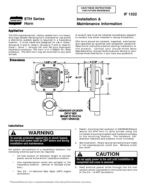
ApplicationThe ETH explosionproof, factory sealed horn is a heavy-duty high decibel vibrating horn intended for use where a distinctive audible signal is required in a hazardous location. It is cUL listed and designed for use in Class I,Groups B, C and D, Class II, Groups E, F and G, Class III,Class I, Zone 1, Groups IIA and IIB plus Hydrogen hazardous locations. The horn is in a NEMA 4X rated enclosure. The ETH horn may be mounted to any solid surface.A conduit seal must be installed immediately adjacent to conduit hub when installed in GroupB locations.ETH horns should be installed, inspected, maintained,and operated by qualified and competent personnel.Read entire instructions before starting installation of this product. Contact your Crouse-Hinds Sales Representative, Crouse-Hinds Customer Service or your Crouse-Hinds Distributor if you have any questions.Installation &Maintenance InformationIF 1322DimensionsETH Series Horn®National Electrical Code is a registered trademark of the National Fire Protection Association.Installation1.Fasten mounting feet as shown in DIMENSIONS andsecure the ETH horn to solid surface using the furnished mounting brackets and hardware suitable to the mounting location. The hardware, 3/8"diameter fasteners and washers, is not furnished.2.See illustration. Power source connections are madein the explosionproof outlet box. Remove outlet box cover.For power connections in a hazardous location, the following external parts will be required.•3/4 inch conduit of sufficient length to contain power source wires within hazardous location.•One explosionproof outlet box suitable to the hazardous location. (Similar to GUJC26 outlet box).•Two 3/4 - 14 National Pipe Taper (NPT) nipple connectors.3.Feed external power wires through the 3/4 inchconduit which is attached to the outlet box with one of the 3/4 - 14 NPT connectors.6.Replace GUJC junction box cover, and tightensecurely.7.Install approved sealing fitting when required bySection 501-5 and/or 502-5 of the NEC plus any other applicable codes. Hazardous location information specifying class and group listing is marked on the nameplate of the unit.8.Pour sealing compound into sealing fitting (whereused) in accordance with instructions provided with the approved sealing fitting and sealing compound package label.SpecificationsCat. No.Voltage Current ETH2312-M4240V AC 0.065A ETH2313-M4120V AC 0.13A ETH2316-M424V AC0.625A ETH2416-M224V DC0.16AMaintenanceAll statements, technical information and recommendations contained herein are based on information and tests we believe to bereliable. The accuracy or completeness thereof are not guaranteed. In accordance with Crouse-Hinds "T erms and Conditions of Sale",and since conditions of use are outside our control, the purchaser should determine the suitability of the product for his or her intended use and assumes all risk and liability whatsoever in connection therewith.Cooper Industries Inc.Crouse-Hinds Division PO Box 4999Syracuse, New Y ork 13221 • U.S.A.© 2000, Cooper Industries, Inc.IF 1322New 6/94P-047550-1639, Issue 31.Frequent inspection should be made. A schedule formaintenance check should be determined by the environment and frequency of use. It is recommended that it should be at least once a year.2.Perform visual, electrical, and mechanical checks onall components on a regular basis.•Visually check for undue heating evidenced by discoloration of wires or other components,damaged or worn parts, or leakage evidenced by water or corrosion in the interior.•Electrically check to make sure that all connections are clean and tight.•Mechanically check that all parts are properly assembled, and operating mechanisms move freely.3.We recommend an Electrical Preventive Maintenanceprogram as described in the National Fire Protection Association Bulletin NFPA 70B.4.Feed the ETH horn power connection wires throughthe other 3/4 - 14 NPT connector which connects the ETH horn to the outlet box.5.Connect all wiring following your system wiringpattern in accordance with the National Electrical Code (NEC). Connect green ground lead to earth ground.Ambient T emperature :The UL Hazardous Locations Listing is “only for use un-der normal atmospheric conditions in an ambient tem-perature within the range of -25C (-13F) to +40C (+104F)”;and within these ambient temperatures, Edwards rec-ommends +25F (-4C) and higher for its function as an audible signal appliance.。
LAUREL电子实时时钟产品说明书

Includes Settings for Real Time Clock Option: RTCSerial Output Option for MAGNA& Intuitive Series:RS232 & RS485 / RS422LAUREL Electronics, Inc.3183-G Airway Ave, Costa Mesa, CA 92626, USA Tel +1 714-434-6131Fax +1 *****************.WarrantyWe warrant this product against defects in materials or workmanship for a period of one year from the date of purchase.In the event of a defect during the warranty period, the unit should be returned, freight (and all duties and taxes) prepaid by the Buyer to the authorised distributor from where the unit was purchased.The Distributor, at its option, will repair or replace the defective unit. The unitwill be returned to the Buyer with freight charges prepaid by the distributor.LIMITATION OF WARRANTYThe foregoing warranty shall not apply to defects resulting from:1. Improper or inadequate maintenance by the buyer.2. Unauthorised modification or misuse.3. Operation outside the environmental specification of the product.4. Mishandling or abuse.The warranty set forth above is exclusive and no other warranty, whether written or oral is expressed or implied. We specifically disclaim the implied warranties of merchantability and fitness for a particular purpose.EXCLUSIVE REMEDIESThe remedies provided herein are the buyer’s sole and exclusive remedies.In no event shall we be liable for direct, indirect, incidental or consequential damages (including loss of profits) whether based on contract, tort or any other legal theory.ContentsWarranty2General Description4Installation Hints5Serial Output board configuring - ASCII6Serial Output board configuring - RTU7Connecting to Tiger weight controller8Setting up your serial port9Specifications10Modbus ASCII11Signal Levels12Fault finding13-RTC Real Time Clock option14-RTC Real Time Clock setup method15Notes16RealT erm examples17, 18Record of revisions20Notes20,21Connections and installing into a display:See main display manual.* Need a manual urgently? Download manuals from our website.General DescriptionThis manual only covers the setup of the serial output option. Please refer to the main display’s operating manual for full specifications, installation methods, safety notices etc. You can download manuals from our website.The serial output option allows you to create an isolated RS232 or RS485 signal which provides data proportional to the nett or gross value shown on the front of your display.This can be used to feed remote devices such as data loggers, displays, PLCs and other peripheral equipment.There are 2 different option boards available:1.An RS232 board, for short distance point to point transfer of data2.An RS485 board, which is suited for longer distance transmission and which maybe part of a group of addressed instruments.Both boards can be set to transmit continuously or can be requested to transmit by a data request.Maximum recommended cable distances if using LOW capacitance screenedcable such as CAT5 cable.Baud Rate RS232RS485 or RS422120050 m (165 ft)1200 m (4000 ft)960020 m (65 ft)150 m (500 ft)1920010 m (33 ft)75 m (250 ft)38400 5 m (16 ft)30 m (100 ft)115200 2 m (6 ft)10 m (33 ft)The serial output is derived from the displayed value, so if you adjust filtering for the display, the serial output will also be filtered and will respond to any input changes at the same speed as the display.The serial output is updated 10 times per second when in continuous mode.Installation Hints for Best PerformanceThis section offers several suggestions which will help you get the best performance from your serial output.1.Use good quality low capacitance twisted-pair screened signal cable. CAT5screened twisted-pair is ideal.2.The cable should be routed away from noisy wiring and devices such as power feeds from inverters, discharge-lighting cables, welder cabling etc, and should preferrably be routed in a dedicated low voltage signalling/instrumentation conduit or cable tray.3.Screened cable should be earthed at the destination end only.4.All wires and screens coming out of the screened cable should be kept as short as possible to minimise pickup of noise.5.If you are going to daisy chain several RS485 devices together on the same data line, you should earth your screen as shown below, paying particular care that you do not earth both ends of any run of of cable.6.Remember to fit a termination resistor to the instruments at each extreme end of the cable run, but no termination resistor on intermediate units.Receiver connection P o l l e d O u t p u t W I T H t e r m i n r e s i s t o rP o l l e d O u t p u t N O t e r m i n a t i r e s i s t o rP o l l e d O u t p u t W I T H t e r m i n a t i o n r e s i s t o rSerial Output Board Configuring - ASCII OutputThe only board you may need to make adjustments to is the RS485 output option board.You can identify it as an RS485 board, because IC4 will be missing.If the display is at the end of the data cable, you will need to fit the 120 Ohm termination jumper.If you have several addressed displays sharing a data line, and find that you occasionally see errors in communication, it may be necessary to fit the line bias jumpers as shown below. This should only be done on the furthest display from the data receiver, so all three jumpers should be fitted.The input/output solder switch must be open - this configures the board as an output driver.The RS232 board looks similar to the RS485 board, but requires no jumpers to be fitted at any time. The input/output solder switch must be open - this configures the board as an output driver.You can identify it as an RS232 board, because IC3 will be missing.Bias +5V on Sig B Bias 0V on Sig A 120 Ohm terminationresistorSerial Output Board Configuring - Modbus RTURealTerm.Connect 120 Ohm terminal to terminal A for line terminationBaud 115200Protocol P2Address 01 to F7t.reP 0t.ChrWith this module, you must set the internal comms parameters on Page 8 as follows:-These are not the Modbus RTU comms parameters,which are set only by the 4switches shown above.See following page for an example of a connection to a Tiger load alarm system via RS485 modbus...Tiger Module Connection ExampleSetting Up Your Serial Output Port You can choose from :-Baud rates in the range 300 to 115200Data formats of 8n1, 7n1, 7e1 or 7o1Protocol C1 for continuous output (Link “Enable” to “Common” on output connector) Protocol P1 for polled outputProtocol P2 for Modbus ASCII modeSpecificationsOutput signal RS232 or RS485 depending on installed board.Isolation250 VAC Optically isolated from input, logic, excitation, power,alarms and serial communications ports.Response speed Derived from displayed value, which is updated 10 times persecond. Any filtering applied to the display will be applied tothe serial data output also.Linearization The analog output is derived from the displayed value, so ifyour display has a nonlinear response, and you are using thedisplay’s linearizer function, the output will follow the displaydirectly.Calendar / Clock option Accuracy better than +/- 10 seconds per month (DS3231SN)Battery backup during power loss. Battery = CR1620 3VLithium.Data strings:Protocol C1 – Continuous output(Enable line to common gives output)Meter sends: 8 characters<CR><LF>e.g.20 20 20 20 20 2D 31 37 0D 0A(-17)decimal position = 020 20 20 20 2D 31 2E 36 0D 0A(-1.6)negative value20 20 20 20 20 31 2E 38 0D 0A(+1.8)positive value20 20 20 20 20 20 4F 52 0D 0A(OR)over range20 20 20 20 20 20 55 52 0D 0A(UR)under rangeProtocol H1 - GPS clock data format for use with ASR-GPSProtocol P1 – Polled ASCIIController sends: <STX> ADDRH:ADDRL r <ETX> e.g. 02 46 37 72 03 ( to device F7) Meter replies <STX> 8 characters <ETX>e.g.02 20 20 20 20 20 2D 31 37 03(-17)decimal position = 002 20 20 20 20 2D 31 2E 36 03(-1.6)negative value02 20 20 20 20 20 31 2E 38 03(+1.8)positive value02 20 20 20 20 20 20 4F 52 03(OR)over range02 20 20 20 20 20 20 55 52 03(UR)under rangeProtocol P2 – Polled ASCII Modbus - See next pageWhen you have finished setting the meter, put the lockout switch in its ON position now, to prevent your settings from being changed.Modbus ASCII Select protocol P2, using the previous page.The displayed value is available as a 32 bit 2’s compliment signed integer in registers0x0000 and 0x0001Register 0x0000 Display value low wordRegister 0x0001 Display value high wordThe decimal point position is available in the low byte of register 0x001E.The high byte is not currently used, but should be masked off to guarantee compatibility with future firmware releases.Some examples:-If meter shows 9Display value reads 9Decimal position reads 0If meter shows 9.9Display value reads 99Decimal position reads 1If meter shows 9.99Display value reads 999Decimal position reads 2If meter shows 9.999Display value reads 9999Decimal position reads 3Typical UART output RS485 data line levels 8n1RS232 data line levels 8n1S t a r t 0111StopLSB MSBLSB MSBThese examples show the transmission of a single ASCII character 2C (0010 1100) which is a Comma, so that you can see the voltages in RS485 and RS232 systems.1 2 4 8 10 20 40 80+7.5V0V-7.5VIdle Start111StopIdle LSB MSBSignal LevelsFault Finding If you are having trouble getting serial data out of the display, first check that you have chosen the correct mode.If you are using Continuous Mode C1Ensure that you have put a link between terminals 18 and 19 to enable the data output.You can test for data with a simple data monitor which you can make with 2 diodes and a resis-tor, as shown below.Provided the baud rate is 9600 or higher, the Green LED should be on for most of the time, and you should see the red LED flicker as data is sent.Check to see if data is arriving at the remote location. If the red LED is lit most of the time, with the green flickering, your wiring may be transposed.If neither LED is lit, check the meter to make sure it is configured to transmit continuously, and check your connections to make sure the cabling and connector terminals used are correct.If you are using Polled Mode P1Check to see whether there is any data activity, using the simple data monitor shown below. If not, check the settings in the polling device.If the polling device is working correctly, check the settings on the display.You can check to see whether a serial output board has been installed in the display - press the outer 2 buttons for around 3 seconds and the display will give a summary of installed software and options.GeneralYou can use your PC to generate and monitor serial data, with a free program called RealTerm which you can download from :-/projects/realterm/This can be very useful in diagnosing communication problems. See end of manual for settings examples.The -RTC option board consists of a precision calendar/clock chip which is battery-backed to maintain timing during periods of power loss.It can be set to automatically correct for summer and winter time clock shifts.It may be used to include date and time in serial data, along with descriptive text, if required. Normally supplied in conjunction with a custom function.In some systems, the board can also be corrected automatically by our ASR-GPS atomic time receiver.Because there are so many ways in which the-RTC board can be used, we provide only basic setup details here, with additional information, specific to your application, supplied with the unit.-RTC Real Time Clock OptionLocation of the RTC board on the main boardRTC Setup MethodApplication NoteConnecting master and slave displays over RS232 or RS485RS232 should be used over short distances only,preferrably under 10 metresof cable lengthT x dR x dC om m .E n a b l eD a t a B D a t a A C o m m .E n a b l eD e m a n dC o m mR x dT x dn i ln i lD e m a n do m ma t a A +a t a B -n i l n i lInput settings on slaveMode = Quant Addr.00S.Chr.00E.Chr.0d bAud 1200dF8n1t.reP .05t.Chr.00to.03S.POS.00d.LEn.00dddddd.dP .AOutput settings on master Baud 1200dF .8n1Prot.C1Addr.00t.rep.05t.chr.00RS232 Slave RS485 Slave(s)RS232 Master RS485 MasterRS485 can be used over cable lengths from 0 to over 1000 metres of cable length.Refer to installation hints in the master and slave manuals for guidance on cable types and screening.RealTerm “Getting Started” Guide 1. Select Baud Rate & Port to suit, other settings as shown. Click ‘Open’ then click ‘Change’3. To view incoming data, click on the ‘Display’ tab, and select either ...a. ASCII - if you want to see the textual value of the datab. Hex - if you want to view the full Hex contents of the transmission (Ideal if you want tosend us your data for diagnostics). Hex gives us the fullest detail of all data in yourtransmission, and includes non-printing characters and control codes.Record of Revisions20 August 2010Revision 0 version of manual released.2 November 2010Rev. 1 Added <LF> to C1 mode data output stream26 November 2010Rev. 2 Software updated to F00.202 February 2011Rev.3 Software updated to F00.2128 February 2011Warranty increased to 3 years and terms added30 July 2013Added RealTerm examples and Modbus RTU section5 November 2013Added Tiger module connection pageSoftware version F00.21Revision:6 Dated: 5 November 2013。
语音闹钟模拟手表说明书
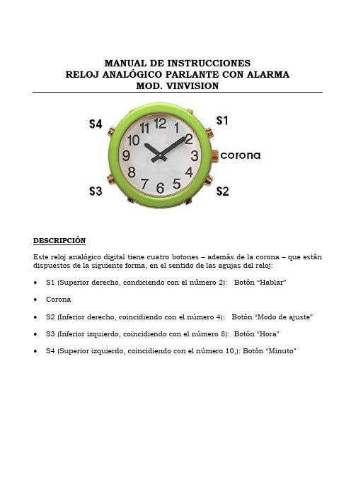
MANUAL DE INSTRUCCIONESRELOJ ANALÓGICO PARLANTE CON ALARMAMOD. VINVISIONDESCRIPCIÓNEste reloj analógico digital tiene cuatro botones – además de la corona – que están dispuestos de la siguiente forma, en el sentido de las agujas del reloj:∙S1 (Superior derecho, condiciendo con el número 2): Botón “Hablar”∙Corona∙S2 (Inferior derecho, coincidiendo con el número 4): Botón “Mod o de ajuste”∙S3 (Inferior izquierdo, coincidiendo con el número 8): Botón “Hora”∙S4 (Superior izquierdo, coincidiendo con el número 10,): Botón “Minuto”AJUSTE DE LA HORAPara ajustar la hora digital, p ulse el botón “MODO DE AJUSTE” (S2) una sola vez para entrar en el modo “Ajustar hora” (se escucha un “bip”). Una vez en esta función, pulse los botones HORA (S3) y “MINUTO” (S4) para ajustar la hora y los minutos respectivamente, hasta que escuche la hora correcta. Después de ajustar hora y minutos, deje transcurrir unos segundos hasta escuchar un pitido indicativo de que el reloj vuelve al la posición de reposo.Para ajustar la hora analógica, tire de la corona hacia fuera, gírela hasta colocar las manecillas en la hora y minutos apropiados y, por último, empuje la corona hacia adentro. Cuando lo haga por primera vez, deberá quitar el plástico de protección de la batería que encontrará en la corona.AJUSTE DE LA ALARMAPulse el botón “MODO DE AJUSTE” (S2) dos veces (bip bip) para entrar en el modo “A justar alarma”. Una vez esté en esta función, presione los botones HORA (S3) Y MINUTO (S4) hasta ajustar la hora y minutos de la alarma respectivamente hasta que escuche la hora de la alarma apropiada. Después de ajustar la alarma, deje transcurrir unos segundos hasta escuchar de nuevo un pitido corto indicativo de regreso a la función reposo. Si detiene el sonido de la alarma pulsando “S2, S3o S4” no volverá a sonar más tarde pero en cambio, si lo interrumpe pulsando el botón “S1” se repetirá ese sonido en intervalos de diez minutos hasta un máximo de cinco veces más. Si deja que la alarma suene hasta su final, quedará cortada definitivamente.ACTIVAR/DESACTIVAR ALARMA Y ACTIVAR/DESACTIVAR ANUNCIO DE HORAS COMPLETASPulse el botón “S2” tres vece s para entrar en el modo activar /desactivar la alarma. Una vez que está en esta función, presione “S4”, botón superior izquierdo, para activar/desactivar la alarma; se sabe si la alarma está activada cuando suena el pitido más agudo y que está desactivada cuando suena el más grave. Después de activar o desactivar la alarma, deje transcurrir unos segundos hasta escuchar de nuevo el pitido corto indicativo de regreso a la hora normal. Si desea escuchar automáticamente la hora cada hora en punto presione “S2” tres veces. Pulsando el botón inferior izquierdo HORA (S3), podrá activar/desactivar esta función. Se activa cuando suena el pitido más agudo y se desactiva cuando suena el pitido más grave. Espere un poco a que suene un pitido breve indicativo de la situación de reposo del reloj.FUNCIONES DEL MODO DE AJUSTEPulse el botón S2 de “MODO DE AJUSTE” tres veces (bip bip bip) y luego presione el botón “HORA” (S3) para activar el aviso horario. Un bip indica que el aviso está activado cada hora, dos bips indican que el aviso horario está activado entre las 7:00 h. y las 21 h., y si no suena ningún bip, el aviso horario está desactivado.Pulse el botón “MINUTO” (S4) para activar la alarma. Un bip indica que la alarma está activada y, si no suena ningún bip, la alarma está desactivada.FUNCIONAMIENTO EN MODO NORMALPulse el botón “HABLAR” (S1) cuando quiera escuchar la hora.Pulse el botón “HORA” (S3) para elegir el formato 12/24 horas. Se escucha un bip cuando está en formato de 12 horas.Pulse el botón “MINUTO” (S4) para seleccionar el sonido que desea para su alarma (melodía, “di-di” o gallo).Cuando suene la alarma, pulse el botón “TALK” (S1) para activar la función de repetición “Snooze” de modo que la alarma sonará de nuevo a los 10 minutos. Pulse el botón “MODE” (S2) para apagar la alarma.NOTA: Si el sonido no se escucha bien al presionar cualquier botón del reloj o la voz no es clara, es hora de cambiar la pila del dispositivo. Funciona con una pila CR2025 para el módulo de voz y con una SR626SW para el módulo analógico.。
木头闹钟说明书

木头闹钟说明书产品功能●同屏显示年、月、日、时、分、星期功能:●闹钟及贪睡功能:贪睡功能开启后,闹钟可以6次闹响,每次闹响间隔5分钟。
没有开启贪睡功能,闹响1分钟后,闹钟功能自动关闭;●时间记忆功能:不使用AC / DC适配器时,LED屏不显示,但时钟内部会继续正常计时,当连接上适配器时,时钟会自动显示当前正常的时间,无需重新设置;● 1/4小时制转换功能;●省电模式:每天下午6点至第二天早上7点,LED显示亮度会自动降低,使人的视觉感到舒适。
使用方法走时及闹铃设置●将AC / DC适配器插上电源,把6V直流电压插头接入时钟6V接口,LED数字屏即发亮显示;●按住SET键3秒进入设定模式,再按动SET键,每按动一次,年、月、日、时、分将依次闪烁。
要设置年、月、日、时、分,只要改变在闪烁的数字即可,按动UP和DOWN 键均可调节,设置结束按SET键,时钟回到正常的走时状态。
星期的设定是全自动的, 它会随着时间的设置而自动改变。
●设置闹铃时间,按动DOWN键显示屏出现AL:- -或AL:on ,每按动DOWN键一次即会转换一次。
按住DOWN键3秒,时的数字在闪烁时,即可通过UP和DOWN键进行调节,要调节分的数字,先按动SET键切换到分的闪烁,同样用UP和DOWN键进行调节,设置结束按SET键,时钟回到正常的走时状态。
闹铃闹响时,按下SET或UP键,闹铃闹响停止,并且关闭闹钟功能,如果闹铃闹响时,按下DOWN 键闹响停止,则贪睡功能自动开启,闹铃会每隔5分钟闹响一次,可连续6次。
若贪睡闹响未达到第6次,在任何一次闹响时,按下SET或UP键,不但闹响停止,同时自动关闭贪睡功能,如果是按下DOWN键,每隔分钟会再闹响一次,直至达到6次闹响为止;●在设定模式下,15秒内不按任何键,时钟将恢复时间显示。
12/24小时制设置正常时间显示下,每按一次UP键,可以实现1/4小时制的转换。
在12小时制式下,数字走到12,这时在时钟的左上角将会出现亮点,表示这时已是下午时间。
科尔·赫塞尔(Cole Hersee)中性安全、后备灯闪灯和闹钟开关开关说明书

Consult factory for switches having specifications other than those shown in this catalog.97Protective Boot98No. 8486-05Terminals: two bullet.Mounting: two #10-32 tapped mounting holes,5⁄8" on centers.Lever: 2 7⁄8" long.Replaces: John Deere AM38713.Heavy Duty Neutral Safety Switches • For applications to 36 VDCO No. 92105Terminals: two female bullet.Mounting stem: 3⁄4"-16 UNF-2A thread,31⁄64" long with aluminum gasket/washer.No. 9242Terminals: two screw.Mounting stem: 9⁄16"-18 UNF-2A thread,5⁄16" long.Replaces: I.H.C. 863187-R91No. 9224Terminals: two screw.Mounting stem: 3⁄4"-16 UNF-2A thread,31⁄64" long with aluminum gasket/washer.Replaces: Clark 224620No. 92102Terminals: two button head, acceptstandard female blade terminals; will matewith Packard 2 pole connector #2962679 orequivalent.Mounting stem: 9⁄16"-18 UNF-2A thread,21⁄32" long.O No. 92102-03Same as No. 92102 except with aluminum gasket/washer.No. 92107-04Terminals: two screw.Mounting stem: 3⁄4"-16 UNF-2A thread,31⁄64" long with aluminum gasket/washer.No. 9162-03Same as No. 9162 except with gasket onmounting stem and golden dipped housing.Replaces: Massey 181140M94No. 9162Terminals: two female bullet.Mounting stem: 3⁄4"-16 UNF-2A thread,31⁄64" long.Replaces: Chrysler 1527835 Clark 733631 SPST • Normally On • Off with plunger depressed, spring return to On.SPST • Normally Off • On with plunger depressed, spring return to Off.Lever Actuated Neutral Safety SwitchSPST • Normally Off, contacts open • Lever actuated to On, spring return to Off.No. 9242-04Wire harness: 22" long, includes two polePackard connector #2984855 with twofemale blade terminals.Mounting stem: 9⁄16"-18 UNF-2A thread, 5⁄16" long.Housing: plasticized for moisture and dirt protection.Replaces: G.M. 702733O No. 9242-07 Self GroundingTerminals: two screw, one terminal groundedto switch housing.Mounting stem: 9⁄16"-18 UNF-2A thread 5⁄16" long.Sealing: terminal insulator sealed againstmoisture and dirt.Replaces: John Deere AT71501No. 9242-01Same as No. 9242 except with brass gasket/washer.No. 83377Molded of durable PVC to repel moisture, dirt, etc.Internal ring engages with groove around switch housing.Fits Cole Hersee switches with 1 1⁄8" hex housing: Nos. 9134, 9162, 9224, 9242,9242-07, 92102, 92103, 92105 and 92107-04.For neutral safety and back-up lamp switches.No. 9224-07Same as No. 9224 except with mounting stem9⁄16"-18 UNF-2A thread and without gasket/washer.ON O Minimum order quantity may apply. Please consult factory or current price list.Silver contacts • Moisture resistant insulators • Corrosion resistant metal housings.Silver contacts • Moisture resistant insulators • Corrosion resistant metal housings.Section N99Vacuum Neutral Safety SwitchesNo. 9253Operating pressure : 9 to 12 inches of mercury.Mounting stem : 1⁄8"-27 dryseal thread (N.P.T.F.) 11⁄32" long.Replaces: A.M. 3156149 Chrysler 1770093,CH-2569Ford C2TA-11516-A Replacement Neutral Safety SwitchFor GM cars and trucks with manual transmissions.Clutch operated. Circuitry per OEM specifications.Back-Up Lamp Switch • Plasticized housingSPST • Normally OnNo. 92007Operating pressure : 7 to 13 inches of mercury.Mounting stem : 1⁄8"-27 dryseal thread (N.P.T.F.) 11⁄32" long.O No. 91123Replaces: G.M. 356113,3990894, 6273381Neutral Safety and Back-up Lamp SwitchesO No. 92001Replaces: Delco D2200G.M. 1993556, 613,618,619, 658, 659, 669,1998677Motorcraft SW-496No. 92021Mounting stem : 3⁄4"-16 UNF-2A thread, 15⁄32" long with seating washer.Replaces: A.M. 3218190, 3232844Chrysler 2932820, 2926495, 4057750, CH-2573Delco 1972523 I.H.C. 424705C1On with plunger depressed, spring return to Off • For use with automatic transmissions.No. 8641Self GroundingOperating pressure : 9 to 12 inches of mercury.Mounting stem : 1⁄8"-27 dryseal thread (N.P.T.F.) 11⁄32" long.Replaces: A.M. 3157963, 3202448, 8127214I.H.C. 1961198-R91No. 91105Terminations : two 18 gauge wire leads 7" long.Mounting stem : 7⁄16" dia.,7⁄16" long with two flats formounting in double "D" shaped hole.Actuator : button head plunger 3⁄8" long.Housing : plasticized, protects against moisture and dirt.Replaces: A.M. 3171244.O Minimum order quantity may apply. Please consult factory or current price list.SPST • Normally OffContacts close at rising vacuum, contacts open at lowering vacuum.Contacts open at rising vacuum, contacts close at lowering vacuum.Neutral Safety and Back-Up Lamp Switches • SPST • Normally Off100No. 91113Transmission mounted • Extra Heavy Duty Terminals : two screw.Mounting stem : 9⁄16"-18 thread, 5⁄16" (7.94mm)long.Compact design for mounting in areas where space is limited.Replaces: Autocar 8E-01360 Brockway 128537Diamond Reo 560-65 Kenworth AT-91-69Mack 1MR-1320 Oshkosh 13320-F1 White 1743529Off with plunger depressed, spring return to On.On with plunger depressed, spring return to Off.O No. 9025Terminals : two screw.Mounting stem : 7⁄16" dia., 7⁄16" long with two flats on stem for mounting in double D-shaped hole.Plunger : 1/2" long.Replaces: Superior School Bus B67176.No. 9052Same as No. 9025 except with button head plunger.Replaces: Ford B9AF, C0AF,51-A15520A Jeep 710412, 721028Motorcraft SW-410.O No. 9176Same as No. 9052 except with blade terminals.Replaces: A.M. 3147682.No. 91115-03Transmission mountedTerminals : Two button head, accept standard female blade terminals; will mate with two pole Packard connector #2962679or equivalent.Mounting stem : 9⁄16"-18 INF-2A thread, 5⁄16" long.Replaces: Jeep 948345, 5353441O No. 9054Terminals : two screw.Mounting stem : 5⁄8"-32 thread,5⁄8" long.Sealing : O-ring in stem and gasket under the terminal insulator.Replaces: Ward School Bus 009 31 014-00.No. 9096-02Terminations : two 16 gauge wire leads 3" long with female bullet terminals: insulator sleeves protect connections.Mounting holes : 13⁄64" dia.,1 1⁄2" on centers.Sealing : plasticized body seals against moisture and dirt.Special diaphragm/mounting bracket sealed to protect operating shaft.Plunger : 1⁄4" long.O No. 9106-02Terminals : four screw.Mounting stem : 7⁄16" dia.,7⁄8" long with flat on stemfor mounting in D-shaped hole.Sealing : gasket sealed terminal insulator.Plunger : 7⁄32" long.Replaces: Chrysler 1479527 Jeep 717589No. 9134Transmission mounted • Extra Heavy Duty Terminals : two female bullet.Mounting stem : 9⁄16"-18 thread, 5⁄16" (7.94mm)long.Compact design for mounting in areas where space is limited.Replaces: Chrysler 1343998, 2198779Motorcraft SW-410.Back-Up Lamp Switches • SPST • Normally OffTwo circuits: No. 1 normally energized; No. 2 energized with plunger depressed, spring return to No. 1.O No. 9208Terminals : two blade and two female bullet.Mounting stem : 7⁄16" dia.,5⁄8" long with two flats on stem for mounting in double D-shaped hole.Sealing : gasket sealed terminal insulator.Replaces: A.M. 3146726.O Minimum order quantity may apply. Please consult factory or current price list.Overdrive Kickdown Switches • SPST • Normally OnOverdrive Kickdown Switch • SPST • On - Momentary OnSection N101Neutral Safety, Back-up Lamp,Back-up Alarm, Overdrive Kickdown Switches O Minimum order quantity may apply. Please consult factory or current price list.Back-Up Lamp • Neutral Safety • Overdrive • Universal Applications.SPST • Normally OnExtra Heavy Duty Weather Resistant SwitchesRubber cap/seal snaps into grooves in plunger and mounting。
LH2H 时钟计数器产品说明书
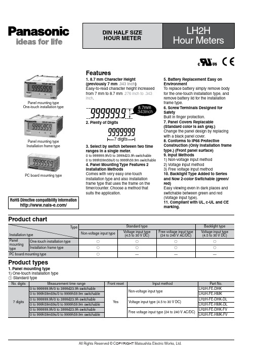
Product types1. Panel mounting type1) One-touch installation typePanel mounting type One-touch installation typePanel mounting type Installation frame typePC board mounting typeFeatures1. 8.7 mm Character Height (previously 7 mm .343 inch )Easy-to-read character height increased from 7 mm to 8.7 mm .276 inch to .343 inch .2. Plenty of Digits3. Select by switch between two time ranges in a single meter.0 to 999999.9h/0 to 3999d23.9h switchable 0 to 999h59m59s/0 to 9999h59.9m switchable4. Panel Mounting Type Features 2 Installation MethodsComes with very easy one-touch installation type and also installation frame type that uses the frame on the timer/counter. Choose a method that suits the application.5. Battery Replacement Easy on EnvironmentT o replace battery simply remove body for the one-touch installation type, and remove battery lid for the installation frame type.6. Screw Terminals Designed for SafetyBuilt in finger protection.7. Panel Covers Replacable (Standard color is ash gray.)Change the panel design by replacingwith a black panel cover.8. Conforms to IP66 ProtectiveConstruction (Only installation frame type.) (Front panel surface)9. Input Methods1) Non-voltage input method 2) Voltage input method3) Free voltage input method10. Backlight Type Added to Series and Now 2-color Switchable (green/red)Easy viewing even in dark places and switchable between green and red (Voltage input type).11. Compliant with UL, c-UL and CE marking.RoHS Directive compatibility information/Product chart2 Backlight typeSpecificationsNote) Only for installation frame type.Applicable standardPart names1. Front reset buttonReset the elapsed time. It does not work when the lock switch is ON. Be aware that battery life will decrease if this switch is used frequently.2. Lock switch (Refer to chart on right.)Disable the front reset button.Note)T urn ON at the LCD side (reset disabled) andOFF at the terminal block side (reset enabled).3. Time range switch (See chart on right).Switch the time range.Note)Always press the front reset button whenoperating the time range switch.4. Time unit stickerUnit seals are included in the package. Affix them in accordance with the time range.Notes)1.❇Default setting when shipped.2.Make the switch setting before installing to panel.Dimensions1. Panel mounting type • External dimensions1) One-touch installation typemm inchGeneral tolerance: ±1.0 ±.039• Panel installation diagramNote)When installing to a 4.5 mm .177 inch thick panel, remove the rubber spacerfirst.When installing the one-touch installation type model, make sure that the installation spring does not pinch the rubber gasket.T o prevent the installation spring from pinching the rubber gasket:1. Set the rubber gasket on both ends of the installation spring (left and right).2. Confirm that the installation spring is not pinching the rubber gasket, and then insert and fix the installation spring in place from the rear of the timer unit.• Terminal layout and wiring diagrams2) Installation frame type• Panel mounting diagramMounting screwsMounting frame • Panel cut-out dimensionsThe standard panel cut-out is shown below.Use the mounting frame (ATH3803) and the rubber packing (ATH3804).(Only installation frame type.)• For connected installation (sealed installation) (Only installation frame type.)Notes)1. Suitable installation panel thickness is 1 to 4.5 mm .039 to .177 inch .2. Waterproofing will be lost when installing repeatedly (sealed installation).A=(1.890×n-.098)0+.0390Input methodNotes)1.2 and 4. (The input and reset circuits are functionally insulated.)2.When using transistor (T r) input, use the right as a guide. (Collector withstand voltage Q 50 V , leakage current < 1 µA)3.Be aware that the application of voltage that exceeds the voltage range of the H level to the count input terminal, and the application of voltage to the reset input terminal, can cause damage to the internal elements.2. PC board mounting type • External dimensions• Terminal layout and wiring diagramsGeneral tolerance: ±1.0 ±.039 mm inchPC board pattern (BOTTOM VIEW)General tolerance: ±0.1 ±.004Note: The AXS212811K is recommended as a compatible connection socket.Q -E , }-w , e -t and S -F are connected internally.An external power supply is required.Connection sockets 28 pin DIP terminalNotes)1.Do not reverse the polarities when connecting the DC voltage for the backlight.2.2 and 4. (The input and reset circuits are functionally insulated.)3.When using transistor (T r) input, use the right as a guide. (Collector withstand voltage Q 50 V , leakage current < 1 µA)4.Be aware that the application of voltage that exceeds the voltage range of the H level to the count input terminal, and the application of voltage to the reset input terminal, can cause damage to the internal elements.Explanation of operation1. Time measuring takes place when the start input is ON.2. When the elapsed (measured) time reaches full scale it returns to “0”, and then measuring starts again from “0”.3. When reset input is ON, the display becomes “0”. Y ou cannot measure during reset input.For PC board mounting type the display disappears while the reset input is ON; however, the display reads “0” when the reset input turns OFF .4. Press the front reset button if you want to perform a manual reset (for panel installation type)Cautions for use1. Non-voltage input typeFor both panel mounting and PC board mounting types1) Never apply voltage to the non-voltage input type. This will damage the internal elements.2) Since the current flow is very small from the start input and reset input terminals (1 and 3 on the panel mounting type and terminals e to t and S to F on the PC board mounting type) please use relays and switches with high contact reliability. When inputting with an open collector of a transistor, use a transistor for small signals in which ICBO is 1 µA or less and always input with no voltage.3) When wiring, try to keep all the input lines to the start and reset inputs as short as possible and avoid running them together with high voltage and power transmission lines or in a power conduit. Also, malfunctions might occur if thefloating capacitance of these wires exceeds 500 pF (10 m 32.808 ft. for parallel wires of 2 mm2). In particular, when using shielded wiring, be careful of the capacitance between wires.PC board mounting type1) For external power supply use manganese dioxide or lithium batteries (CR type: 3V).2) Always reset after external power is applied and confirm that the display reads “0”.3) Make the wiring from the battery to the hour meter unit as short as absolutely possible. Also, be careful of polarity.4) Calculate battery life with the following formula.t = A/It: battery life [h]I: LH2H current consumption [mA]A: battery capacity until minimumoperation voltage is reached [mAh] 5) Hand solder to the lead terminal. Do not dip solder. With the tip of the soldering iron at 300°C 572°F perform soldering within 3 seconds (for 30 to 60 W soldering iron).2. Voltage input type1) Be aware that applying more than 30 V DC to start input terminals 1 and 2, and reset input terminals 3 and 4 will cause damage to the internal elements.2) For external resetting use H level (application of 4.5 to 30 V DC) between reset terminals 3 and 4 of the rear terminals. In this case, connect + to terminal 3 and – to terminal 4. This is the valid polarity; therefore, the hour meter will not work if reversed.3) When wiring, try to keep all the inputlines to the start and reset inputs as shortas possible and avoid running themtogether with high voltage and powertransmission lines or in a power conduit.Also, malfunctions might occur if thefloating capacitance of these wiresexceeds 500 pF (10 m 32.808 ft. forparallel wires of 2 mm2).3. Free voltage input type1) Use start input terminals 1 and 2 forfree voltage input and reset terminals 3and 4 for non-voltage input.2) Be aware that the application ofvoltage that exceeds the voltage range ofthe H level to the start input terminal, andthe application of voltage to the resetinput terminal, can cause damage to theinternal elements.3) Since the current flow is very smallfrom reset input terminal 3, please userelays and switches with high contactreliability.4) When inputting a reset with an opencollector of a transistor, use a transistorfor small signals in which ICBO is 1 µA orless and always input with no voltage.5) T o reset externally, short reset inputterminals 3 and 4 on the rear.6) Input uses a high impedance circuit;therefore, erroneous operation may occurif the influence of induction voltage ispresent. If you plan to use wiring for theinput signal that is 10 m or longer (wirecapacitance 120 pF/m at normaltemperature), we recommend the use ofa CR filter or the connection of a bleederresistor.4. How to reset multiple panelmounting type counters all at once(input is the same for count)Non-voltage input typeNotes)e the following as a guide for choosingtransistors used for input (Tr).Leakage current < 1 µAe as small a diode (D) as possible in theforward voltage so that the voltage betweenterminals 3 and 4 during reset input meetsthe standard value (0.5 V).( At IF = 20 µA, forward voltage 0.1 andhigher.)Voltage input typeNote)Make sure that H (reset ON) level is at least 4.5V.5. Backlight luminanceT o prevent varying luminance amongbacklights when using multiple Backlighttypes, please use the same backlightpower supply.6. Acquisition of CE markingPlease abide by the conditions belowwhen using in applications that complywith EN 61010-1/IEC 61010-11) Ambient conditions• Overvoltage category II, pollution level 2• Indoor use• Acceptable temperature and humidityrange: –10 to +55°C, 35 to 85%RH (withno condensation at 20°C)• Under 2000 m elevation2) Use the main unit in a location thatmatches the following conditions.• There is minimal dust and no corrosivegas.• There is no combustible or explosivegas.• There is no mechanical vibration orimpacts.• There is no exposure to direct sunlight.• Located away from large-volumeelectromagnetic switches and powerlines with large electrical currents.3) Connect a breaker that conforms toEN60947-1 or EN60947-3 to the voltageinput section.4) Applied voltage should be protectedwith an overcurrent protection device(example: T 1A, 250 V AC time lag fuse)that conforms to the EN/IEC standards.(Free voltage input type)7. Terminal connectionTighten the terminal screws with a torqueof 0.8 N·cm or less.。