Nodemcu指引PDF
VuLink CI In-Situ 设备用户指南说明书
Manual de usoÍndice de contenidosSímbolos (3)Información de seguridad (4)Componentes necesarios (5)Cable (5)Instrumento (5)Software (5)Pilas (5)Accesorios (6)Cómo funciona (7)Ajustes de Vulink (9)Retire la lengüeta de las pilas y presione el botón (9)Solución de problemas de conectividad de red (9)Añada otro instrumento y presione el botón (opcional). (10)Entender los LEDs (10)Registro con VuLink (12)Registros de VuLink (12)Registros de instrumentos (12)Uso de HydroVu (13)Uso de VuLink con VuSitu (14)Creación de alarmas (15)Uso de VuLink con un servidor FTP (16)Conexión de un instrumento de pulso a VuLink (18)Configuración de un instrumento de pulso con VuSitu (19)Añadir el instrumento a VuLink. (19)Configúrelo. (19)Entender las tarjetas SIM de VuLink (21)Actualización de VuLink (21)Controles (22)Especificaciones (23)Símbolos importantes en este manualSímbolos importantes en el productoEste símbolo indica información crítica de seguridad. Ignorar el texto que acompaña a este símbolo puedeprovocar lesiones o la muerte debido a una manipulación inadecuada.De acuerdo con la Directiva de Residuos de Aparatos Eléctricos y Electrónicos de la UE de 2005 y otras directivas posteriores, VuLink no debe desecharse junto con la basura doméstica convencional. Compruebe la normativa local sobre residuos electrónicos/eléctricos antes de deshacerse de un dispositivo VuLink.Directiva RAEE: Eliminación de VuLink al final de su vida útil PrecauciónUtilización correcta de VuLinkInstalación y sustitución de las pilasInstalación de la antena1 Cable2 Instrumento3 Software4 PilasCable robusto con sistema Twist-Lock Aqua TROLLVea los datos, gestione losinstrumentos, cree alarmas ymodifique la configuración deVuLink desde su navegador.Comuníquese con VuLink desde cualquierdispositivo móvil con Bluetooth y con laaplicación móvil VuSitu.Baro TROLLSoftware deHydroVuAplicación móvil VuSituNivel TROLL Rugged TROLLConecte VuLink con un instrumento Aqua TROLL, Baro TROLL,Level TROLL o Rugged TROLL.Con o sin ventilación.Antena de telefonía móvilDivisor de cables RuggedAdaptador universal decargaKit de montajeReferencia: 0043630Referencia: 0095500 (con ventilación)Referencia: 0085840 (sin ventilación)Referencia: 0101000Referencia: 0095570La antena de telefonía móvil permite una fuerte conectividad a la red móvil.Con el divisor de cable Rugged, puede conectar hasta 8 instrumentos con VuLink.Para acoplar instrumentos de medición de flujo y dispositivos que no disponene de un conector Twist-Lock, utilice el adaptador universal de carga.El kit de montaje permite fijar VuLink a un poste, una pared u otra estructura.123MosquetónDispositivo de telemetría VuLinkInstrumentoVuLink cuelga de la parte superior de un pozo con su mosquetón desmontable.VuLink aporta energía a los instrumentos de monitorización, transmite los datos a la nube y le notifica cuando es necesario realizar algún mantenimiento.Un instrumento de In-Situ mide la calidad y/o el nivel del agua.Coloque la antena y conecte un instrumento.Después de conectar la antena externa o de a bordo y elinstrumento, siga las instrucciones de las siguientes páginas deesta guía de inicio rápido.24telemetría.Visite la página y cree una cuenta.Haga clic en el enlace de la página de telemetría en el menú a la izquierda de la página. A continuación, haga clic en Añadir un VuLink .Abra su cámara web y escanee el código QR en su dispositivo, o escriba el código de registro en el campo disponible.o c l i cPulse en 2G para modificar la configuración de red deVuLink. Pulse enGuardar .VuLink debería ahora ser capaz de conectarse a una red y sincronizarse con HydroVu.Presione el botón Todos los ajustes en la parte inferior dela pantalla.Pulse en Red móvil en lapantalla de Ajustes.Retire la tapa de las pilas girándola en sentido antihorario y tirando hacia abajo.Asegúrese de que la antena está bien colocada antes de continuar.Presione el botón. Todos los LEDs se encienden. A continuación, cada LED cambia de color en función del estado del dispositivo.Retire la lengüeta amarilla para permitir que la corriente pase a través de las pilas. Vuelva a colocar la tapa.VuLink funciona con los instrumentos Aqua TROLL, Level TROLL, Baro TROLL y Rugged TROLL. Siga los siguientes pasos para comenzar a transmitir datos.5 Retire la lengüeta de las pilas y presione el botón.Solución de problemas de conectividad de redVuLink se conecta al nuevo instrumento y a la red de datos.Desconecte el instrumento de VuLink. Añada otro. Presione el botón.VuLink se conecta a HydroVu o a un servidor FTP .Todos los LEDs indican el estado actual del dispositivo. Consulte la sección siguientepara obtener más detalles.Entender los LEDsRojo fijo Verde fijoVerde intermitenteRojo intermitente La carga de la batería es de al menos el 75%.La carga de la batería entre el 25% y el 50%.La carga de la batería está entre el 50% y el 75%.La carga de la batería inferior al 25%.Estado de la batería7 Añada otro instrumento y presione el botón (opcional).Parpadeo rojo y verdeUn LED rojo y verde intermitente indica un problema con las pilas. No haga uso de VuLink en estas condiciones. Compruebe las pilas y vuelva a colocarlas si es necesario.Rojo fijoVerde fijoVerde intermitenteRojo intermitenteBuscando un instrumentoNuevo instrumento no encontradoConectado al instrumentoNo hay instrumentos conectados a VuLinkRojo fijoRojo intermitenteVerde fijoVerde intermitenteIntentando conectarse a la redConectado a la redNo se puede conectar a la redLa antena de VuLink está desconectada o VuLink no puede localizar una red móvil.Rojo fijoVerde fijoAzul fijoAzul intermitenteVerde intermitenteRojo intermitenteDispositivo no reclamadoCarga exitosaConectado por BluetoothListo para conectarConectando y cargando datos a HydroVuFallo en la conexión con Estado de la conexión del instrumentoEstado de la conexión a la redEstado de la conexión con la nubeEstado de la conexión BluetoothProgramar un reg-istro en VuLink conla aplicación móvil VuSitu.un registroen el instru-con VuSitu.archivos de registro con Registros de VuLinkRegistros de instrumentos112Ver sus datos en HydroVu.Crear y editar paneles de controlGestionar alarmasConfigurar notificacionesVer ubicacionesConfigurar dispositivos detelemetríaCargar datosEditar parámetros calculadosGestionar usuariosVer sus datosOpciones del menú de la barra lateral/Páginas de HydroVuPantalla del dispositivo de telemetría conectadoPulse en la opciónConfiguración del menú y luego elija Alarmas en tiempo real .Para crear una alarma, pulse en Añadir una alarma entiempo real.Seleccione el parámetro que debe activar la alarma y establezca los límites.Conéctese a VuLink con laaplicación móvil VuSitu.Introduzca sus credenciales FTP . A continuación, pulse en Probar y Guardar .VuLink prueba la conexión con el aplicación muestra los resultados de la prueba.Pulse en Todos los ajustes .Seleccione el Servicio de telemetría en la nube .a bdgPulse en el botón de radio junto a FTP .cefPuede configurar VuLink para cargar los datos en un servidor FTP a través de VuSitu. Tenga preparado el nombre del servidor FTP Recuperación de datosAcceda a la pantalla del Servicio de telemetría en la nube como se muestra arriba.Introduzca una fecha y hora de inicio, o un número de registro de inicio.Pulse en Inicio .Pulse en Cargar datos faltantes .Lea el mensaje emergente sobre los gastos de datos. Pulse en Enviar datos si desea continuar.Si la carga se produce con éxito, VuSitu muestra unaconfirmación.Componentes necesariosCableado con el adaptador universal de carga (LBUA)• Cable Rugged con bloqueo Twist-Lock con un extremo pelado y estañado • Adaptador universal de carga (LBUA)• Cable (del LBUA al instrumento de pulso)• Instrumento de pulso • VuLinkLeyenda del cable RuggedColor del cableSeñal Marrón Salida del pulsoNegro TierraRojo Alimentación (opcional)Azul Sin usar Verde Sin usarBlancoSin usarConecte el extremo con el Twist-Lock de un cable Rugged a VuLink.Conecte los hilos marrón y negro del otro extremo del cable Rugged al adaptador universal de carga.Corte los cuatro cables sin uso. Pase los cables desde el otroextremo del LBUA hasta elinstrumento de pulso.A VuLinkHasta el pulso instrumentoAñadir el instrumento a VuLink.Configúrelo.Inicie VuSitu y conéctese a VuLink.Conecte el instrumento a VuLink con un cable. Presione en el botón Añadirde VuSitu.VuSitu muestra un mensaje de confirmación. Pulse en OK paradescartarlo.Pulse en el menúdesplegablede InstrumentosConectados .Pulse en el menúdesplegablede Instrumentos Conectados .Pulse en Añadir nuevo .Seleccione el botón de radio del instrumento medidor de pulso .Pulse en el instrumento.Seleccione la frecuencia baja o alta.Frecuencia baja: Elija uno de los tres parámetros integrados o cree un parámetro personalizado.Añada pluviómetros y otros dispositivos de pulso a VuLink con la configuración de pulso de VuSitu.engranaje junto al campo dela unidad para seleccionar unaIntroduzca un valor mínimo ymáximo.Introduzca una frecuenciamínima y máxima en hercios.Pulse enGuardarparaconfirmar la configuracióndel instrumento medidor deIntroduzca el valor de un pulsoen las unidades seleccionadas.Pulse en Guardar. VuSitumuestra el mensaje de"Guardando".VuSitu muestra el mensaje de"Guardando".Alta frecuencia: SeleccioneAlta Frecuencia y elija unparámetro y una unidad.Tarjeta SIM externaSIM integradaVuLink trata de utilizar una tarjeta SIM externa para todas las comunicaciones si hay una. Si la comunicación a través de la SIM externa falla, VuLink utiliza en su lugar la tarjeta SIM integrada.Si no hay una tarjeta SIM externa, VuLink utiliza su SIM integrada para todas las comunicaciones.21Mosquetón 2Estado de la conexión Bluetooth 3Estado de la batería 4Estado de la conexión 5Estado de la conexión a la red 6Estado de la conexión con la nube 7Antena 8 Botón de encendido 3Pilas Compatible con 3 x celdas D (1,5V - 3,6V) alcalina/Li-SOCl2 [cloruro de litio y tionilo]/Li-MnO2 [dióxido de litio y manganeso]Tiempo de funcionamiento(informe de 24 horas,batería de Li-MnO2)Hasta 12 años*.Tiempo de funcionamiento(informe de 24 horas,batería alcalina)Hasta 3 años*Precisión del reloj Menos de 1 minuto de desviación al año con capacidad de sincronización con la horafacilitada por la red para una precisión de +/- 1 segundoTipo de red4G LTE Categoría M1 (LTE-M) / NB-IoT (Narrowband) con opción a 2GBandas de radio LTE Global - B1(2100), B2(1900), B3(1800), B4(AWS 1700), B5(850), B8(900), B12(700),B13(700), B18(800), B19(800), B20(800), B28(700)Protocolos HTTPS (HydroVu), SMS (alarmas)Proveedor de datos Itinerancia global gratuita** integrada (consulte el anexo de la lista de redes para obtener más detalles: /VuLinkNetworks), ranura adicional de 4FF para soporte de SIM de tercerosAntena Conector SMA-MGPS Precisión de hasta 3 m, antena incorporadaFormato de archivo (sinHydroVu)CSVConfiguración remota CompatibleLongitud total19.1”Diámetro 1.85”Peso2,2 libras/1,0 kg (con pilas alcalinas y mosquetón incluidos, sin incluir la antena)Materiales Ryton (carcasa), PVC (tapa de las pilas), titanio (conector Twistlock, cáncamo), acero inoxidable 316 (mosquetón), silicona (tapa del teclado), latón (conector de antena SMA), policarbonato (etiqueta), Viton (juntas tóricas)Temperatura dealmacenamiento-20°C a 60°CTemperatura defuncionamiento-20°C a 50°C (Li-SOCl2/Li-MnO2), 5°C - 40°C (Alcalina)Protección contra lapenetración Dispositivo: IP68 Sistema: Hasta IP68 según especificación de la antenaProtocolos Modbus sobre RS-485, SDI-12, Pulso de baja/alta frecuencia (máximo 40 khz)Conectores 1 "Twistlock" In-Situ (admite varios instrumentos a través de un divisor de cable Rugged,TROLL Net Hub o un adaptador universal de carga)Conexiones simultáneas Hasta 8 instrumentos (máximo total de 75mA dispuestos a los instrumentos conectados a16V)Ventilación Incorporada en todos los modelos, no requiere desecanteCompensaciónbarométrica Incorporada en todos los modelos para la compensación automática de las lecturas de nivel Precisión del barómetro+/- 1 hPaAlarmas Configurables en función de las lecturas de los instrumentos y de los parámetros deldispositivoBotón de encendido Máximo total de 75mA dispuestos entre los instrumentos conectados a 16V (destinadosnormalmente a alimentar un solo instrumento)Configuración inalámbrica Compatible con Bluetooth Low EnergyTasa de registro De 1 minuto a 7 díasTasa de transmisión De 5 minutos a 7 díasMemoria512 MB (soldados a la placa de circuito)Potencia máxima de salidadel transmisor Todas las bandas LTE FDD: +23 dBm +/- 1dB (conducido)GSM900: +32,5 dBm +/- 1dB GSM1800: +29,5 dBm +/- 1dB (conducido) EGPRS900: +27,0 dBm +/- 1dB EDGE1800: +26,0 dBm +/- 1dB (conducido) Bluetooth: +5,5 dBm +/- 0,35 dB (EIRP)。
nodemcu开发教程实例
nodemcu开发教程实例NodeMCU是一种基于ESP8266的开源硬件,具有WiFi功能和Lua脚本语言支持。
以下是一个简单的NodeMCU开发教程实例,可以帮助你入门NodeMCU开发。
1. 准备开发环境首先,你需要准备一个开发环境。
在Windows上,你可以使用Arduino IDE;在Mac或Linux上,你可以直接使用官方的ESP8266工具箱。
确保你已经安装了ESP8266模块的支持。
2. 安装NodeMCU固件在Arduino IDE中,选择“工具” -> “开发板” -> “NodeMCU ”。
然后,将ESP8266模块通过USB数据线连接到电脑。
Arduino IDE会自动检测到模块并为其安装所需的驱动程序。
3. 编写Lua脚本在Arduino IDE中,创建一个新的Lua脚本文件。
以下是一个简单的示例脚本,用于在串口控制台输出“Hello, NodeMCU!”:```luafunction setup()print("Hello, NodeMCU!")endfunction loop()-- 在这里编写循环代码end```4. 烧录固件在Arduino IDE中,选择“文件” -> “上传”。
等待上传完成。
上传成功后,你的NodeMCU模块就可以运行Lua脚本了。
5. 调试和测试将模块通过串口连接到电脑,打开串口控制台。
你应该能够看到“Hello, NodeMCU!”的输出。
如果你想要测试其他功能,可以在“loop()”函数中编写相应的代码。
这只是一个简单的入门教程实例,NodeMCU还有更多功能和玩法等待你去探索。
希望对你有所帮助!。
ESP8266NodeMCU手把手入门(实操篇)——读取传感器的值
ESP8266NodeMCU⼿把⼿⼊门(实操篇)——读取传感器的值物联⽹使得现实世界中的实体和数字世界⽐以往任何时候都更紧密地联系在⼀起。
NodeMCU作为其中的⼀个重要设备,作⽤之⼀就是与传感器相连以实现万物互联通讯。
这篇关于NodeMCU的实操篇以⼟壤湿度传感器和DHT传感器为例,详细介绍了如何使⽤ESP8266获取传感器的值及相应的⽰例代码。
之所以选择这两个传感器作为⽰例进⾏讲解,是因为⼟壤传感器输出值的信号引脚输出模拟信号,⽽DHT传感器的信号引脚输出数字信号,在使⽤过程中也需要引⼊库(也可以不使⽤库,代码相对复杂)。
当你理解了这篇⽂章后,NodeMCU与其它⼤多数传感器的通信也就迎刃⽽解了。
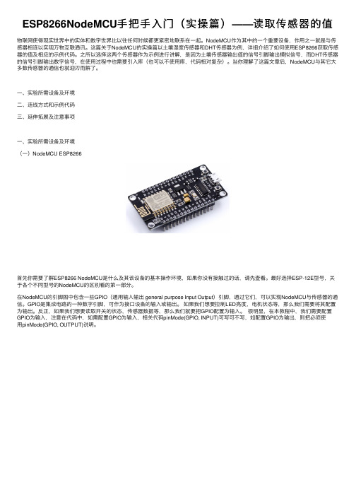
⼀、实验所需设备及环境⼆、连线⽅式和⽰例代码三、延伸拓展及注意事项⼀、实验所需设备及环境(⼀)NodeMCU ESP8266⾸先你需要了解ESP8266 NodeMCU是什么及其该设备的基本操作环境,如果你没有接触过的话,请先查看。
最好选择ESP-12E型号,关于各个不同型号的NodeMCU的区别看的第⼀部分。
在NodeMCU的引脚图中包含⼀些GPIO(通⽤输⼊输出 general purpose Input Output)引脚,通过它们,可以实现NodeMCU与传感器的通信。
GPIO是集成电路的⼀种数字引脚,可作为接⼝设备的输⼊或输出。
如果我们想要控制LED亮度,电机状态等,那么我们需要将其配置为输出。
反正,如果我们想要读取开关的状态,传感器数据等,那么我们就要把GPIO配置为输⼊。
很明显,在本教程中,我们需要配置GPIO为输⼊,注意在代码中,如需配置GPIO为输⼊,相关代码pinMode(GPIO, INPUT)可写可不写,如配置GPIO为输出,则把必须使⽤pinMode(GPIO, OUTPUT)说明。
NodeMCU ESP8266的引脚图(图源:)(⼆)⼟壤传感器YL-69⼟壤传感器⽤于获取⼟壤湿度参数,即⼟壤中的⽔分百分⽐。
恩智浦半导体Kinetis K22系列MCU引导加载程序用户指南说明书

00000005981LF-000EOS Power 1-855-837-4225Give us a callInternational: 1-555-555-55551-415-281-38661IntroductionThis document describes how to use the Kinetis bootloader toload a user application on a Kinetis K22 series MCU.2Overview This guide describes the steps required to use the Freescale-provided Kinetis bootloader utilities to both load the Kinetisbootloader image and use the bootloader to update the userapplication section of flash. Upon reset, the bootloader detectsthe presence of the user application and launches it. Thebootloader also provides a means to suppress the applicationlaunch and remain in the bootloader command processor inorder to refresh the user application. This full-circleenvironment enables application developers to easily installnew applications onto Kinetis devices, and providesmanufacturers a way to update Kinetis devices in the fieldwithout the need for a debugger.2.1Kinetis bootloaderUser's Guide Rev 0, 12/2014Demo Application User's Guide for the FRDM-K22F and TWR-K22F120M Freescale Platforms © 2014 Freescale Semiconductor, Inc.Contents1Introduction................................................................12Overview.. (13)Hardware configuration (24)Kinetis bootloader application...................................45The host utility application. (7)6Windows GUI updater application (8)7Appendix A Kinetis flash-residentbootloader operation (11)8Revision History (14)The Kinetis bootloader serves as the standard bootloader for all Kinetis devices. It provides a standard interface to the device via all of the available peripherals supported on a given Freescale Kinetis device. The Kinetis bootloader interface comes in several forms, ranging from ROM, serial flashloader, or a customized flash-resident bootloader. All future Kinetis devices will arrive with a ROM containing the Kinetis bootloader, while others will arrive pre-programmed from the factory with a one-time-use serial flashloader. For a customized interface, customers can leverage the Kinetis bootloader source code to create a unique flash-resident bootloader that is both compatible with tools that understand the bootloader interface, and are capable of supporting application-specific features. Freescale provides utilities to demonstrate how to interface with the bootloader.2.2Host utilityThe blhost.exe utility is a cross-platform host program used to interface with devices running the Kinetis bootloader. It can list and request execution of all of the commands supported by a given Kinetis device running the bootloader.2.3led_demo user applicationThe led_demo_FRDM-K22F*.bin and led_demo_TWR-K22F120M*.bin programs are example demo firmware applications used to demonstrate how the Kinetis Bootloader can load and launch user applications.2.4Host updaterThe KinetisUpdater.exe host application is a Windows® GUI program used to update the user application image on the device running the Kinetis bootloader firmware application.2.5Toolchain requirementFirmware projects:•IAR Embedded Workbench for ARM version 7.20 (or later)Host projects:•Microsoft® Visual Studio® Express 2013 for Windows Desktop•Microsoft® .NET Framework 4.5 (included in Windows 8)•Microsoft® Visual C++ Redistributable for Visual Studio 2013 (vcredist_x86.exe)•Python v2.7 ( )3Hardware configurationThis section describes how to set up the hardware in order to run the Kinetis bootloader example.Demo Application User's Guide for the FRDM-K22F and TWR-K22F120M Freescale Platforms, Rev 0,12/20143.1FRDM-K22FThe bootloader example application assumes that all platform jumpers are set to their default positions.Figure 1. Front side of FRDM-K22F platform3.2TWR-K22F120MThe bootloader example application assumes that all module jumpers are set to their default positions.Demo Application User's Guide for the FRDM-K22F and TWR-K22F120M Freescale Platforms, Rev 0,12/2014Figure 2. Front side of TWR-K22F120M module4Kinetis bootloader applicationThis section describes how to connect the platform to the computer and download the pre-built Kinetis bootloader application.4.1Connect the Freedom platformThe following section assumes the board is set up with the default factory configurations. For more information, visit /FRDM-K22F .For Windows PCs, install the mbed serial port driver in order to communicate with the Kinetis device over a serial port.1.Download and install the latest mbed Windows serial port driver from /handbook/Windows-serial-configuration .2.Connect the OpenSDA USB connector, J5 for the FRDM-K22F board, to the USB port on a PC.3.Install the mbed serial port driver.Demo Application User's Guide for the FRDM-K22F and TWR-K22F120M Freescale Platforms, Rev 0,12/2014Figure 3. mbed serial port in Windows Device ManagerFigure 4. Driver software installation4.1.1Install the Kinetis bootloader onto the Freedom PlatformTo install the bootloader application, drag or copy and paste the freedom_bootloader.bin file from <install_dir>/targets/ MK22F51212/binaries onto the MBED mass storage device.Demo Application User's Guide for the FRDM-K22F and TWR-K22F120M Freescale Platforms, Rev 0,12/2014Figure 5. Install the Kinetis bootloader on the FRDM board4.2Connect the Tower moduleThe following section assumes the board is set up with the default factory configurations. For more information, visit /TWR-K22F120M .For Windows PCs, install the P&E Micro OpenSDA drivers in order to communicate with the Kinetis device over a serial port.1.Connect the module to the USB port on a PC using the module's debug USB connector.2.Download the driver package from the P&E Micro website ( /opensda/ ) and run the installer.3.After the installer finishes, plug in the module and open the Windows Device Manager to show the COM port numberassigned to the virtual serial port.Figure 6. OpenSDA virtual comport in Windows Device ManagerDemo Application User's Guide for the FRDM-K22F and TWR-K22F120M Freescale Platforms, Rev 0,12/2014Figure 7. Driver software installation4.2.1Install the Kinetis bootloader onto the Tower ModuleTo install the bootloader application, drag the tower_bootloader.srec file from <install_dir>/targets/MK22F51212/binariesonto the TWR-K22F120 mass storage device.Figure 8. Install the Kinetis bootloader on the TWR board5The host utility applicationThis section describes simple use of the blhost host utility program to demonstrate communication with the Kinetisbootloader.Demo Application User's Guide for the FRDM-K22F and TWR-K22F120M Freescale Platforms, Rev 0,12/2014•Open a command prompt in the directory containing blhost. For Windows, it is <install_dir>/bin/win.•Type blhost --help to see the complete usage of the blhost utility.For this exercise, verify the Kinetis device is running the bootloader firmware application.•Press the "Reset" button on the platform.•Note what the COM port that the platform is connected to. Refer to step 3 of section 4.1. For this guide, the device is connected to COM23.•Type blhost -p COM23 -- get-property 1 to get the bootloader version from the Kinetis bootloader.•Something similar to the screen shot below indicates that blhost.exe is successfully communicating with the Kinetisbootloader on the platform.Figure 9. Host communication with Kinetis bootloader6Windows GUI updater applicationThis section describes how to use the Windows GUI updater application, KinetisUpdater.exe, to install an example user application onto the platform.6.1Installing the user applicationThe FRDM-K22F platform is used in this example. Similar steps can be used for the TWR-K22F120M module.1.Click the "Reset" button on the platform.2.Navigate Windows Explorer to the <install_dir>/bin/win/KinetisUpdater directory.3.Double-click the KinetisUpdater.exe file to launch the app.NOTEIf the application fails to launch, check that the .NET Framework 4.5 and theVisual C++ Redistributable 2013 are installed as noted in Toolchain requirements.4.Start at the orange home screen. Click "Select Device".•The blue device configuration page will show.•Select the COM23 device from the drop-down box.•Click "Home" to return to the home screen.Demo Application User's Guide for the FRDM-K22F and TWR-K22F120M Freescale Platforms, Rev 0,12/2014Figure 10. Select the COM port5.Click "Select Image".•The blue image configuration page will show.•Select the led_demo_FRDM-K22F_a000.bin application image from the <install_dir>/apps/led_demo/binaries directory using the "Browse" button.•Set the base address to 0xA000.•Click "Home" to return to the home screen.Figure 11. Browse for the user applicationDemo Application User's Guide for the FRDM-K22F and TWR-K22F120M Freescale Platforms, Rev 0,12/20146.Figure 12. Set base address for application file7.The "Update" button should now be enabled. Click "Update".•The blue update page will now be displayed.•Click the "Update" button to write the application image to the device flash.•Click "Home" to return to the home screen.Figure 13. Perform the update8.Click the "Exit" button.9.At this point, the led(s) on the target board should be noticably blinking indicating that the Kinetis Bootloadersuccessfully installed the led_demo user application.6.2Returning to Flash-resident bootloaderTo return to the Kinetis bootloader interface, simply hold SW3 and press and release the "Reset" button on the target board.When the device resets, the Kinetis bootloader will detect the press on SW3 and not jump to the user application. Verify youare in bootloader mode by again running the blhost.exe tool as done earlier.Figure 14. Back to the Kinetis bootloader interfacePressing the "Reset" button alone will allow the Kinetis Bootloader to again launch the led_demo application.7Appendix A Kinetis flash-resident bootloader operationThis section describes the linkage between the Kinetis flash-resident bootloader and the user application. The demonstration described above illustrates a fairly simple collaboration between the Kinetis bootloader and the led_demo application. The considerations are:•The flash-resident bootloader is located in flash at address 0.•The user application is located in flash above the bootloader at BL_APP_VECTOR_TABLE_ADDRESS as defined in <install_dir>/apps/targets/<mcu>/src/bootloader_config.h•The vector table for the User Application must be placed at the beginning of the application image.•The Bootloader Configuration Area (BCA) must be placed at 0x3C0 from the beginning of the image.7.1Memory map overviewFigure 15. Device memory mapFigure 16. User application vector table and Bootloader Configuration Area (BCA)7.2User application vector tableThe Kinetis bootloader checks BL_APP_VECTOR_TABLE_ADDRESS+0 for the User Application stack pointer andBL_APP_VECTOR_TABLE_ADDRESS+4 for the User Application entry point. Initially, this area is expected to be erased(0xFF) and the bootloader remains in its command interface.Once a User Application is installed to BL_APP_VECTOR_TABLE_ADDRESS, the bootloader jumps to the application after a period specified by peripheralDetectionTimeoutMs in the Bootloader Configuration Area (BCA).7.3Bootloader Configuration Area (BCA)The Bootloader Configuration Area is located at offset 0x3C0 from the beginning of the User Application image. This information is read by the Kinetis bootloader early during the bootloader initialization in order to set up clocks and gather other information relevant to detecting active peripherals. If the first four bytes of the BCA are not ‘kcfg’, the bootloader does not use any information from the BCA on flash.For this tutorial, the led_demo application set the tag field to ‘kcfg’ and the peripheralDetectionTimeoutMs to 500 sothat the bootloader would only wait 500 milliseconds before launching the led_demo application instead of the default 5second wait period.8Revision HistoryThis table summarizes revisions to this document.How to Reach Us: Home Page: Web Support: /support Information in this document is provided solely to enable system and software implementers to use Freescale products. There are no express or implied copyright licenses granted hereunder to design or fabricate any integrated circuits based on the information in this document. Freescale reserves the right to make changes without further notice to any products herein.Freescale reserves the right to make changes without further notice to any products herein. Freescale makes no warranty, representation, or guarantee regarding the suitability of its products for any particular purpose, nor does Freescale assume any liability arising out of the application or use of any product or circuit, and specifically disclaims any and all liability, including without limitation consequential or incidental damages. “Typical” parameters that may be provided in Freescale data sheets and/or specifications can and do vary in different applications, and actual performance may vary over time. All operating parameters, including “typicals,” must be validated for each customer application by customer’s technical experts. Freescale does not convey any license under its patent rights nor the rights of others. Freescale sells products pursuant to standard terms and conditions of sale, which can be found at the following address: / SalesTermsandConditions.Freescale, the Freescale logo, and Kinetis are trademarks of Freescale Semiconductor, Inc., Reg. U.S. Pat. & Tm. Off. Tower is a trademark of Freescale Semiconductor, Inc. All other product or service names are the property of their respective owners. ARM and Cortex are registered trademarks of ARM Limited (or its subsidiaries) in the EU and/or elsewhere. mbed is a trademark of ARM Limited (or its subsidiaries) in the EU and/or elsewhere. All rights reserved.© 2014 Freescale Semiconductor, Inc.Document Number K22BTLDRDEMOUGRevision 0, 12/2014。
Mi.Node M 安装工具用户指南说明书

Product Name Document Title1Mi.Node M Install ToolUser Guide880-0199-001Firmware version 1.0.11Document version 2.03/29/2017ContentsOverview (5)Keypad Operation (6)Features (6)User Interface (7)Battery (7)Charger and Battery Status symbols (7)Walk-by meter reading (8)To read one meter (8)To read all meters (8)To read meters currently in “Install” mode (9)To log all meters (9)To read meters using Transparent Mode (9)Viewing readings (10)To view readings in a route (10)To view readings not in a route (10)To view last 9 readings (10)To select a reading (10)Interpreting a meter read (11)Troubleshooting (12)Confirming successful installation (12)To test an installation (12)Alternative installation test (12)Troubleshooting read/installation issues (13)Troubleshooting transmission issues (13)Meter data (14)To clear Meter Data (14)To clear List Data (14)To change RF frequency (14)To change Key Click (14)To change Message Click (14)Handheld-to-computer interface (15)OverviewThe handheld Mi.Node M Install Tool collects readings from a single meter, or collects and stores data from up to 1024 separate water meter accounts when used with EZExport software. When used as an installation tool, it can verify correct wiring connections and successful node activation and communication.The basic installation process:•Physically attach the Mi.Node M unit (mounted on a wall or in a pit)•If necessary, connect the Mi.Node M unit’s wires to the meter register wires•The wiring connections for Mueller Systems products is always Red to Red, White to White and Black to Black.o For other wiring or manufacturers’ devices, consult Mueller Systems support.•Swipe a magnet across the side of the Mi.Node M unit to the right of the logo. This process initiates the node reading of the register. Example:•Confirm the Install Tool displays the meter reading shown on the register. Verify signal level, and absence of event/duration codes.The compact unit is about the size of a standard smart phone. Powered by a lithium battery, the install tool is charged via USB cable and is rated to run for an entire shift of continuous operation. TheMi.Node M Install Tool is capable of operating on two different frequencies. Its antenna is flexible to accommodate meter readers while clipped to a belt or pocket.Note: This document covers only M networks; procedures in this document differ from those for systems using older v3 and v4 Mi.Nodes.Keypad OperationUse the keypad to select commands or enter digits as needed.Important keys include:•ENT: Turns on unit, advances to main menu•CLR: Goes back or cancels current process•1-4: Select menu optionsFeaturesUse the Mi.Node M Installation Tool for small scale meter reading and meter installation. Options:1.Meter Reading – Walk by meters to gather readings, view results. You can collect readings froma list loaded to the Install Tool, as well as all meters in range.2.Installation Tool – Verify meter-to-node connection and successful data transmission3.Datalog Confirm - Confirm the node is transmitting logged meter readings to the Mi.Node MMobile transceiver.4.Unit Setup – change the tool’s frequency, mute soundsUser InterfaceThe Mi.Node M Install Tool’s screen displays menu commands and data. Battery strength is indicated at the top right of the screen.Start screen If the unit is off, press ENT twice to view the main menu. Individual commands are described in the following procedures.The Mi.Node M Install Tool’s screen displays menu commands and data. Battery strength is indicated at the top right of the screen.BatteryTo charge fully, the Install Tool should be plugged into a standard 5-volt USB powered by either an electric outlet or computer for approximately 7-8 hours. If you are plugging the install tool into a computer, make sure the computer is plugged in and configured to provide power to the USB when it times out or is powered down. (By default, most Windows computers supply power to a USB while turned off. Check your computer’s USB Root Hub Power Management Properties, accessed via Device Manager.)Charger and Battery Status symbolsA battery strength indicator is displayed in the upper-right corner of the display screen.Install Tool is plugged into a USB source, battery is charging.Battery is almost depleted, less than 10% charge remaining. Battery is 20-40% charged.Battery is 50-80% charged.Battery is 95-100% full, charge process complete. Note: The install tool turns itself off after ten minutes of non-use, unless it is operating in Transparent mode or Logging mode.Walk-by meter readingThe Mi.Node M Install Tool collects readings from any node in its range. When displaying or uploading reads, it keeps data from meters in the route/list (List Data) separate from the rest of the meter reads (UnList Data).You can read up to 1,024 meters within close range of the tool as you walk.To read one meterThis procedure assumes the Mi.Node M unit has been swiped with a magnet after wires are connected.1. Press ENT or CLR as needed to access the main menu.2. Press 2 > 1 > 2 (Receive One).3. Type the 10-digit ID on the meter’s node. (Note: if the number has fewer than 10 digits, enter leading zeroes. For example enter “0012345678” if the node’s ID has only 8 digits.4. Press ENT .5. Verify the ID on the node label matches the ID shown on the screen and note the Read. See Interpreting a meter read for more information.To read all metersThis procedure is recommended only if a limited number of meters is in range. This mode listens for all meters, in or out of a route.1. Press ENT or CLR as needed to access the main menu.2. Press 2 > 1 > 1 (Receive All). The Install Tool scrolls through all received reads quickly on the screen. Press CLR to stop reading and return to the previous menu. Press any other key to pause/resume reading.To read meters currently in “Install” modeThis procedure scans for up to three Mi.Node M units transmitting an initial beacon sent when the unit is swiped during the install process. You can use it to verify the installation you just performed is transmitting its install beacon. The Mi.Node M unit sends the beacon for two minutes, and the install tool listens for one minute.1.Press ENT or CLR as needed to access the main menu.2.Press 2 > 1 > 3 (Receive Install).3.If the screen displays the register ID you are interested in, press 1, 2, or 3, as it corresponds tothe ID you want.The tool displays the meter data information.To log all metersThis procedure captures datalogs from all Mi.Node M units within receiving range of the install tool. You can pause the process, but cannot view data on the screen. Datalogs are stored in the install tool for later upload to a computer.The install tool runs continuously when in Logging mode; it does not turn off automatically after 10 minutes. Exit Logging mode if you want the unit to turn off automatically.The screen will show the List Count, the Non List Count, the register ID and meter read of the last collected reading.1.Press ENT or CLR as needed to access the main menu.2.Press 1 > 1 > 1 (Start Logging). Wait for the logging to complete, or press CLR to stop loggingand exit to the Meters Logging menu screen.To read meters using Transparent ModeThis procedure requires a laptop or other mobile device. This mode listens for all meters, in or out of a route.1.Press ENT or CLR as needed to access the main menu.2.Press 1 > 2 (Transparent Mode).Note: The Install Tool runs continuously when in Transparent mode; it does not turn off automatically after 10 minutes. Exit Transparent mode if you want the unit to turn off automatically.Viewing readingsTo view readings in a route1.Press ENT or CLR as needed to access the main menu.2.Press 1 > 1 > 2 (View List Data).To view readings not in a route1.Press ENT or CLR as needed to access the main menu.2.Press 1 > 1 > 3 (View UnList Data).To view last 9 readings1.Press ENT or CLR as needed to access the main menu.2.Press 2 > 2 (View Last 9).The top row of the display shows the number of the reads currently shown, for example, reads 7 through 9.To select a readingThe Install Tool displays three readings at a time. Press ENT to scroll through the list three meter readings at a time.To access details of a single read, press the number of the reading (1-9) to access the read. For example, if “4-6” is displayed, you can press 4, 5, or 6 to see more details about that register’s reading.Interpreting a meter readWhen the Mi.Node M Install Tool successfully reads a Mi.Node M unit, it displays consumption, status, and other information described below.The top line is a header for ID and Read, and the received signal strength is at top right. Each line of the display shows: Line 2:• Meter ID: If ID has fewer than 10 digits, leading zeroes are added. • Meter read: 4 to 9 digits. The reading is right-aligned. Line 3:• Status code – “St ”o Good Reado Small Leak – register has detected a leak of approximately 1/8 gpm or less o No Flow o Back Flowo High Leak – register has detected a leak of approximately 1/4 gpm or more o Q-Mark – register’s wheel(s) not fully rolled over to the next digit o No Response o SSR Tamper o SSR Removal• Duration: Length of time the condition persisted, usually a range. “W ” indicates weeks. Line 4:1. Battery strength () — Good, Low, VLow (very low), Fail. If VLow, the Mi.Node M unitshould be replaced immediately. If Low, replace within 6 months. 2. SSR battery status () – (if an SSR is attached to a Mi.Node M unit): Good, Low.3. Last received transmission – “Rx ” time elapsed in seconds since the last transmission receivedfrom node. This number is updated as the Time elapsed since the last transmission received, inseconds.TroubleshootingConfirming successful installationYou can use the Mi.Node M Install Tool to verify that a newly installed meter is correctly connected to the Mi.Node M unit, and is transmitting reads.After the Mi.Node M unit has been physically installed and (if necessary) connected to the register, swipe the unit with a magnet to force an immediate read of all register data.To test an installationUse the standard procedure for reading a single meter.1.Press ENT or CLR as needed to access the main menu.2.Press 2 > 1 > 2 (Receive One).3.Type the 10-digit ID shown on the Mi.Node M unit’s label. Enter leading zeroes if there are lessthan 10 digits.4.Press ENT.The Mi.Node M Install Tool scans for the reading. The display should show “St Good Read” in the status line if the read was successful. See Interpreting a meter read for information on other responses from the Mi.Node M unit.Additionally, make note of:•The ID number shown. If it matches the label on the Mi.Node M unit, this means the unit has not properly received the register’s ID.•Any error codes returned from an electronic register.•Signal strength (dBm) shown in the upper-right corner. The lower the number, the stronger the signal.Alternative installation testWhen swiped, a Mi.Node M unit broadcasts a datalog file. In this procedure, the Mi.Node M Install Tool ‘listens’ for units broadcasting a datalog.1.Press ENT or CLR as needed to access the main menu.2.Press 3 (Datalog Confirm).3.Swipe the Mi.Node M unit of the meter to be read.4.Look for the ID of the register just installed (or the ID on the Mi.Node M unit’s label).Troubleshooting read/installation issuesWhen investigating field issues, it is recommended you bring a spare Mi.Node M unit and register that are verified operational. You can swap the node and register individually to help identify issues. Condition Possible Cause Recommended StepsStatus = No Response Mi.Node M unit is notconnected to register 1.Examine wiring and connectionsfor damage or detachment.2.Try replacing node with anoperational node. Swipe andcheck for a reading.3.If unsuccessful, and wiring is OK,try swapping in the operationalregister.4.If still unsuccessful, it could be anissue internal to the device(s). 5.If a successful read was made,ensure the Install Tool displaysthe correct Mi.Node M unit ID.Status = Q Mark Typically, register was unable todetermine every odometerwheel’s position. Check the register to see if a wheel is in transition. This normally clears as the odometer wheels continue to turn with additional flow.Battery level below Good Mi.Node M unit battery isdegrading. Replace Mi.Node M unit if battery level is Very Low (VLow).Troubleshooting transmission issuesKeyboard commands recommended here begin at the main menu. Condition Possible Cause Recommended StepsNo communication from the node to the receiver (inability to read node) Mi.Node M unit fell off itsmount, or is buried undermud, water, debris, etc.In worst case, waterinfiltration rendered nodeinoperable.•Physically examine node to verifyproper installation or environmentalissues causing problems.•Check connection between Mi.NodeM unit and register; reconnect ifnecessary.Mi.Node M unit transmissionis blocked or unit ispositioned poorly.Physically examine node to verify properinstallation or environmental issuescausing problemsNo reading from the Cut wire, problem at 1.Check connection between Mi.Nodemeter register connection points to theregister or node, or at theinline (Nicor) connector withregister.M unit and register; reconnect ifnecessary.2.Attempt to perform a read (2 > 1 >2, enter ID).Meter dataYou can clear data, which erases readings without deleting the downloaded route.To clear Meter Data1.Press 1 > 3 > 1 (Clear Meter Data).2.Press ENT to clear the data or CLR to cancel and return to the previous screen.To clear List Data1.Press 1 > 3 > 2 (Clear List Data).2.Press ENT to clear the data or CLR to cancel and return to the previous screen.To change RF frequency1.Press 4 > 1 (Channel Set Select). The screen displays an arrow pointing at one channel or theother.2.Press 1 or 2 - the option without the arrow.3.Press ENT.To change Key ClickTo enable or disable the clicking sound when a key is pressed:1.Press 4 > 2 (Key Click). The screen displays an arrow pointing to either 1-Key Click Off or 2-KeyClick On.2.Press 1 or 2 to select Off or On.3.Press ENT.To change Message ClickTo enable or disable the clicking sound when the unit processes messages such as reads:1.Press 4 > 3 (Message Click). The screen displays an arrow pointing to either 1-Msg Click Off or2-Msg Click On.2.Press 1 or 2 to select Off or On.3.Press ENT.Handheld-to-computer interfaceThe Mi.Node M Install tool is charged with a USB cable plugged into a desktop or laptop computer. The USB cable also transmits data from the tool to the computer. The computer must have EZ Export installed.A driver automatically configures the Mi.Node M Install Tool as a serial device with its own COM port defined on the computer. To view The COM designation, navigate on the computer to the Device Manager in the Windows Control Panel. With the Mi.Node M Install Tool unplugged from the computer, scroll to the Ports (COM & LPT) list (if this list is not present, it is because there are no COM ports present on the computer). When the tool is connected to the computer and powered on, its COM port designation will appear in the Ports (COM & LPT) list.About Mueller SystemsWhere Intelligence Meets Infrastructure® Mueller Systems provides Smart Meteringsolutions to optimize the delivery and use of water and energy. Municipalities that supply water, electricity or gas — or any combination of the three services — need innovative ways to increase efficiencies, reduce costs, conserve water and energy, and improve customer service. The ® Mueller Infrastructure Network for Utilities from Mueller Systems meets that need.Mueller Systems develops meters and metering systems that are a Smart Move™ for the most demanding applications including residential, commercial and fire-line meters, advanced metering infrastructure (AMI)/automated meter reading (AMR) systems and related products. We provide utilities with infrastructure technology—including the water industry’s first AMI system with 2-way multidirectional network configuration—that enables them to access the intelligent, actionable data needed to increase efficiencies, reduce costs, conserve water and energy, and improve customer service.Mueller Systems is part of Mueller Water Products, Inc., a leading manufacturer and marketer of products and services used in the transmission, distribution and measurement of water. Contact:Customer SupportMonday – Friday 8am – 7pm ET (800) 323-8584******************************* ************************** Mueller Systems48 Leona Drive Middleborough, MA 02346 Mueller Systems10210 Statesville Blvd. Cleveland, NC 27013Contact:Customer SupportMonday – Friday 8am – 7pm ET (800) 323-8584******************************* **************************。
FDS PRO-MX-CDU MCDU 设置手册说明书
SETUP GUIDE/MANUALForFDS PRO-MX-CDU/MCDUContents1.0Product Information 42.0Compatible Software List 53.0Features 64.0FDS-CDU Software Installation for Testing 7 4.1FDS-CDU Software is located here 7 4.2FDS-CDU Software Installation 74.3“No Sync”95.0Sim-Avionics (Sim-A) CDU Instructions 11 5.1Setup Instructions 115.2Sim-A Line Set-up 146.0ProSim CDU Instructions: 15 6.1ProSim CDU Setup 15 6.2ProSim CDU Assignments 17 6.3Moving the ProSim CDU to the CDU screen 206.4ProSim Screen Setup 207.0AEROWINX PRECISION SIMULATOR (PSX) CDU SETUP 22 Start the FDS-CDU Software. (Fig.20) 22 7.1PSX CDU Configuration 237.2PSX Special Notes 248.0PMDG CDU Setup 25 8.1PMDG Software located here 258.2Sim-Connect for Prepar3d 259.0Air Sim Tech (AST) MCDU Set-up 2610.0Project Magenta CDU Setup 2810.1Project Magenta Special Notes 2911.0iFly CDU Setup (B737 Only) 3011.1iFly Installation Steps 3012.0Nav Data (Navigraph) 3212.1Note: Software suites do not come with the latest Nav Data installed. 3213.0FAQ Frequently Asked Questions 33 13.1I can’t get the CDU to work at all.33 13.2The dis play doesn’t look right.33 13.3Can I run 2 CDU’s on 1 PC?33 13.4I don’t see the software CDU on my Screen33 13.5The screen shows “No Sync”331.0 Product Information•NEW! VGA LCD (800x600 or 1024x768 Resolution)•All Metal Construction (Bezel and Structural Components)•Dual Use Design (Drop in DZUS Rail Compliant and/or Desktop)•New Dimpled Injection Molded Keys•Open Source Interface for Simple Integration with available CDU Software (SDK Required)•PnP with Sim-Avionics, Project Magenta and AST•Dimmable Key Brightness•Dimmable LCD Display Brightness (Software Dependant)•Super Realistic Tactile Feel Keys (With Audible Click)•Dimensions: 8.95" x 5.75" Footprint (Dzus Compliant)API included with Interface SoftwareFDS A320 MCDU and FDS B747/777PLEASE NOTE: The FDS-PRO-MX-CDU does not function unless you have installed the FDS-CDU Controller Software. Or available Avionics Suite software that “talks” directly to the CDU/MCDU.(IE: Sim-A uses the SYSBoard Controller instead) Configuring the CDU by following the instructions on the following pages will enable you to turn on the backlighting, LCD Screen anduse the keyboard.2.0 Compatible Software List•aeroSystems•AST (Limited Support)•iFly (Limited Support)•Level D (Limited Support)•PMDG B737NGX and B777•Project Magenta (Limited Support)•ProSim B737 and A320•Aerowinx Precision Simulator (PSX)•Sim-Avionics B737 and B777API documentation included with the install package.3.0 FeaturesDZUS fasteners and non-skid rubber feetFunctioning Dimmer for key backlighting andScreen dimming (software dependent)4.0 FDS-CDU Software Installation for Testing4.1 FDS-CDU Software is located herehttp://www.tekworx.ca/downloads.htmlCDU software v3.1.5 (Current version at time of this manual creation: Jan/2018) LINKInstall the software on each computer that will have a CDU plugged into it via a USB cable (self-installing). Single PC users only need to install it once and assign each CDU/MCDU to the correct position (Captain or F/O)NOTE: Sim Avionics users can assign 3 CDU’s (Capt ain, F/O and Observer for B777 Simulators). A nice feature for full functionality!4.2 FDS-CDU Software InstallationPlug in the USB cable to the computer and CDU/MCDU and wait for the hardware to be found.Fig.1Start the FDS-CDU software; it will appear down by the clock in the Task Bar.Fig.21. Right click on the ICON and select Configure. (Fig.2(2. Select Test Module from the drop-down menu. (Fig.3)3. Select CDU1 in the Drop-down menu. (Fig.3)4. Click on SAVE.Fig.3 Fig.4The Test Module will show a CDU and you wi ll be able to test all the keys, LED’s, backlighting and LCD screen. Also, the value assigned to the dimmer knob staring at 0-255. You can click in the boxes on the right or click on each LED position and the LCD screen in the CDU picture. Select Airbus fo r MCDU’s and also the Airbus style you are using (FDS-A320-PRO-MX-MCDU is modelling the Thales version)4.3 “No Sync”“No Sync” means there is no video Connection. Check the cables and /or adapters being used. If you see “No Sync” on the FDS-CDU Test Module that is normal and does not reflect what you will see on the CDU Hardware.Fig.5Fig.6CDU in Test mode with LCD and backlighting turned on5.0 Sim-Avionics (Sim-A) CDU InstructionsUsing the SYS Controller Software (New since 2014)5.1 Setup Instructions1) Connect CDU USB, power (12V) and VGA cable.2) Open the SYS Controller software in the main Sim-A folder.3) Software will open. (Fig.7)Fig.74) CDU Hardware is initialized.Assign the CDU(s) by opening “Enable Program Mode” on right side of SYS Controller (Fig.8)Fig.85) List of SYSBoards or Devices Connected is shown. Select CDU Assignment Tab. (Fig.8)6) Press any Key on the CDU you want to assign.Fig.9Number appears in yellow. Assign to the CDU, in this case CAPTAIN CDU (Fig.9)7) CDU will show assigned and Press “SAVE” (Fig.10)Fig.108) Once assigned the CDU screen and backlighting will turn on.9) Start the Sim-A CDU software by clicking on the exe in the CAPT CDU folder.Fig.1110) The CDU appears on the Main PC screen as above. Drag the CDU over to the CDUscreen. (Fig.11)11) Once positioned i n the FDS CDU hardware screen, press the “END” key on yourcomputer keyboard. The CDU will go to Full Screen.12) Close the Sim-A CDU program to allow the screen settings to be written to the CDU inifile in Sim-A13) Re-start the CDU program and the CDU will display the CDU screen in your CDUhardware.*Follow the Line Set-up procedure on page 18 of the Sim-Avionics User manual located in the Main Sim-Avionics folder in the Documentation folder.5.2 Sim-A Line Set-up1. Press the MENU key2. Press SIM3. Press NEXT PAGE4. Press Line Setup5. Change each line number by entering the new number with the keypad and select theline you want to adjust. The line will move, adjust the number till lined up. Do this for each line. IE: Shows 58 enter 68, select the LSK and the text will shift down. (if youmake a mistake enter a number close to what it was and select the LSK to return the line). Only required for the left side, it will adjust the right side as well.6. Press NEXT PAGE to go to the next menu page.7. This is for the Title, Margin and ScratchpadPress SAVE when completed.6.0 ProSim CDU Instructions:In the most recent pre- releases ( 1.39.38 ) ProSim now supports the FDS CDU with its own version of the TEKWorx driver (interfaceITAPI.dll ) ProSim will then recognize the CDU. Please install our latest prerelease as explained here:/forum/viewtopic.php?f=81&t=4932Uninstall the FDS drivers / TEKWorx software if installed. FDS_CDU software can be used as a Test module if required for testing. The FDS-CDU software cannot be running at the same time as the Avionics software.6.1 ProSim CDU SetupFig.12Make sure you have selected “FDS Hardware Support” b y selecting Config/Configuration thenDrivers. (Fig.12)Open the ProSim CDU software and select the exe file.Fig.136.2 ProSim CDU Assignments1) Right-click on the CDU screen and select Config. (Fig.14)2) Enter the ProSimSystem Server IP Address to connect the CDU software and showing a green Connected indicator. (A)3) Select the CDU position (Captain or First Officer) (B)Fig.14 A BSelect the Drivers Tab1) Select Enabled2) Select the CDU serial numberFig.15Back to the Options Tab1) Set the Fonts as shown or find the settings you prefer.2) Select Start Full screen3) Deselect Show Frame and Show BorderFig.166.3 Moving the ProSim CDU to the CDU screen1) Drag the CDU (as shown) over to the screen of the Hardware CDUFig.176.4 ProSim Screen SetupDo the Screen Layout following the instructions provided by ProSim.This is the ProSim software setup for the Screen Layout. Fig.18Fig.18 Fig.19 Fig.197.0 AEROWINX PRECISION SIMULATOR (PSX) CDU SETUPStart the FDS-CDU Software. (Fig.20)Open the software; it will appear on the Task Bar.Fig.20Right-click on the ICON and select Configure. Select Aerowinx Precision Simulator (PSX) from the drop-down menu as shown below. (Fig.21)Fig.217.1 PSX CDU ConfigurationWhen PSX is selected the Configure Icon to the right of the drop-down menu will darken. If the CDU is being configured from a networked computer other than the PSX Server the IP address and Port number of the Server should be selected. The port number can be obtained from looking at the PSX server’s Preferences – Basic page. Fig.22Fig.22In the Assignment Tab use the Drop-down menu to select the position of the CDU as shown in the following screenshot. For PSX the CDU position is defined as left, center and right. Left is the captain’s CDU, Center is the Observer’s CDU on the aft aisle stand and Right is the First Officer’s CDU. All three CDUs can be on the same PC if desired. Fig.23Fig.23Click on SAVE. Right click on the ICON and select EXIT. (Fig.23)7.2 PSX Special NotesOptimal video card resolution to match the PSX program is 800 x 600.Once set up and initialized, the screen, the keypad backlighting and the indicator lights are controlled by the state of the B747-400 simulator. When the aircraft is unpowered, all CDUs are inoperative. When powering up a CDU, it takes 20 seconds until the CDU is operative. The left CDU is powered when the Battery switch is ON and the Standby Power Selector is set to AUTO or BAT. The center CDU is powered when AC bus 1 powered. The right CDU is powered when AC bus 1 or 2 is powered. (AC busses can be powered by APU PWR, EXT PWR, or by engine generators.) The CDU screen intensity is set by the BRT dimmer knob on the CDU. The keypad backlighting is controlled by the Aisle Stand Panel Lighting Potentiometer on the Overhead Panel.8.0 PMDG CDU SetupCovers the B737NGX and the B777 only.Follow instructions included with the downloaded softwareLocation of User Manual after installation: C:\FDS PMDG Interface8.1 PMDG Software located hereFDS-PMDGController V2.0 is the latest version. Please review and follow the supplied instructions to get the CDU up and running. Make sure you have installed the Sim-Connect files if running Prepar3D. Sim-Connect is not installed automatically. Must be installed by the user.8.2 Sim-Connect for Prepar3dInstall all three P3D Sim-Connect versions:C:\Program Files (x86)\Lockheed Martin\Prepar3D v3\redist\Interface\FSX-RTM\retail\lib\SimConnect.msiC:\Program Files (x86)\Lockheed Martin\Prepar3D v3\redist\Interface\FSX-SP1\retail\lib\SimConnect.msiC:\Program Files (x86)\Lockheed Martin\Prepar3D v3\redist\Interface\FSX-SP2-XPACK\retail\lib\SimConnect.msiNOTE:No need for the Japanese or Russian version (Unless you really want to…)9.0 Air Sim Tech (AST) MCDU Set-upFDS-CDU Software is located here:http://www.tekworx.ca/downloads.htmlCDU software v3.1.5 link is hereOpen the software; it will appear down by the clock in the Task Bar.Fig. 241)Right click on the ICON and select Configure. Select AST Software from the drop-down menu.2)Click on SAVE.3)Right click on the ICON and select EXIT.Fig.25Follow the MCDU instructions that come with AST software for proper installation. AST uses a “Key Teacher” program to assign keys to the MCDU software. Also, the ICFG program will allow you to adjust the screenhttp://www.airsimtech.eu/NOTE: You need to choose the “No window” in the Drop-Down menu. Be sure that the MCDU software is NOT running when using the “Key Teacher” tool.Limited support is available to AST currently, FDS does not have any software set-up for testing purposes.10.0 Project Magenta CDU SetupFDS-CDU Software is located here:http://www.tekworx.ca/downloads.htmlCDU software v3.1.5 LINKOpen the software; it will appear down by the clock in the Task Bar.1) Right click on the ICON and select Configure.2) Select Project Magenta from the drop-down menu.3) Click on SAVE.4) Right click on the ICON and select EXIT.Fig.2610.1 Project Magenta Special NotesThe RCDU software requires the Project Magenta (No Window) when configuring the FDS-CDU software. (Fig.26)/resources/MagentaDoc11.pdf CDU Information starts on Page30. Set-up and INI file information can be found in this document. Follow the instructionsprovided.11.0 iFly CDU Setup (B737 Only)/pcupload/FDS-CDU-iFly-Module-v1.0.zipFollow instructions below. Install FDS-CDU-iFly-Module software after FDS-CDU Controller Software.11.1 iFly Installation Steps1. First, you will need to download and install the FDS CDU Controller software from http://www.tekworx.ca/downloads.phpFDS-CDU ver 3.1.5 LINK*This is the main controller software required to interface the hardware to any software.2. After successfully running FDS-CDU iFly Module v1.0.exe the installer has made thechanges to allow the CDU Controller to interface with the CDU on the FSX iFly aircraft.What did the installer do :●You will find a new folder : \FDS iFly Interface\CDUThis contains iFlyCDU.dll which is the iFly addon module for the CDU Controller software.● A Registry entry is also added during the installation to register the iFlyCDU.dll with theCDU Controller software:HKLM\Software\TEKWorx Limited\FDS-CDU\Extra Modules\iFly3. Now all of the components have been installed you need to assign the connected CDU's as either Captain or FO in the CDU Controller software.To do this you should connect the CDU's to you computer via the USB cables and run the CDU Controller software –FDS-CDU.exeIt will show as an icon in the sys tray on the taskbar (down by the clock) (Fig.27)Fig.27. Now Right-Click on the icon and select “Configure” from the popup menu. (Fig.27)iFly should be available and selected in the “Available Modules” dropdown menu. One or Two devices will be displayed in the Assignment window depending on how many CDU's you have connected. Using the Assignment dropdown menu, you can select Captain or FO.By pressing some keys on one of theCDU's, you should see Keypresses shown in the Input Location Data box. This will help you to differentiate between two CDU'sPress SaveThen Right-Click on the CDU Controller icon again and select ExitYou have now configured the CDU Controller Software/pcupload/FDS-CDU-Module-iFly-Manual.pdf Limited support is available to AST currently, FDS does not have any software set-up for testing purposes.12.0 Nav Data (Navigraph)The necessary files that are required for the CDU to have the latest data are available here:/www/default.aspFMS Data page:/www/fmsdata.aspScroll down to the appropriate Avionics Suite and select the file. You need to have asubscription to download the latest files.12.1 Note: Software suites do not come with the latest Nav Data installed.For more info: /www/fmsdata_about.aspSelf-Installing software.*Consider purchasing the “Ultimate Package” for Full Airport Charts and Nav Data.13.0 FAQ Frequently Asked Questions13.1 I can’t get the CDU to work at all.Don’t panic, do you have the VGA, USB and 12V power connected?Have you installed and configured the FDS-CDU or Avionics software?Have you used the FDS-CDU software Test Module?Have you read the manual?13.2 The display doesn’t look right.This is a Windows setting. You need to go into the Display Adapter Properties in the Display Settings. “List all Modes”Check the Frequency (Hertz) in the Video card settings. Some configurations (ie: video cards, settings etc) need to be adjusted.Change the hertz from 60 to the next one and try. Several to choose from.Also check if you should use 800 x 600 or 1024 x 768. More hertz settings in there.We haven’t found the exact method to get the right setting. Seems to change by computer. We will update the manual once we sort that out.13.3 Can I run 2 CDU’s on 1 PC?Yes, you can with Sim-Avionics and ProSim. Only change the CDU config file to start the FDS-CDU software in the Captain’s CDU. Select each CDU in the CDU Configuration menu.Project Magenta currently you cannot ru n the RCDU unless it is the “Top Window”. Testing has shown you will need a second PC. Mirroring a Pedestal CDU from the Captain’s CDU is an option for B747 and B777. (A VGA amplifier will be required)Sim-Avionics allows multiple CDU’s running independent ly allowing the 3 in a B777...13.4 I don’t see the software CDU on my ScreenYou need to drag the software CDU screen over to the actual CDU Hardware screen. Common installation step that is missed.13.5 The screen shows “No Sync”“No Sync” on the CDU screen means there is no video Connection. Check the cables and /or adapters being used.If you see “No Sync” on the FDS-CDU Test Module that is normal and does not reflect what you will see on the CDU Hardware. It Indicates the screen is turned “ON”.。
nodemcu API说明
API说明flash 错误注意:有些模块在烧写之后启动,串口输出ERROR in flash_read: r=。
这是因为模块原来的flash内部没有擦除。
可使用blank512k.bin,内容为全0xFF,从0x00000开始烧入。
烧入之后可以正常运行。
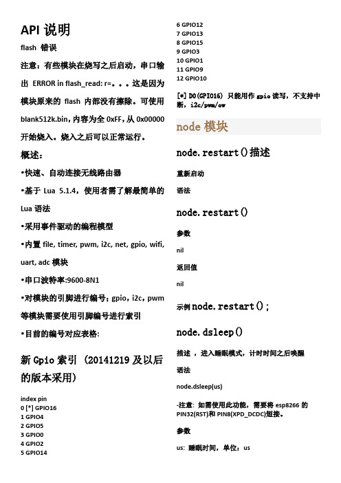
概述:•快速、自动连接无线路由器•基于Lua 5.1.4,使用者需了解最简单的Lua语法•采用事件驱动的编程模型•内置file, timer, pwm, i2c, net, gpio, wifi, uart, adc模块•串口波特率:9600-8N1•对模块的引脚进行编号;gpio,i2c,pwm 等模块需要使用引脚编号进行索引•目前的编号对应表格:新Gpio索引 (20141219及以后的版本采用)index pin0 [*] GPIO161 GPIO42 GPIO53 GPIO04 GPIO25 GPIO146 GPIO127 GPIO138 GPIO159 GPIO310 GPIO111 GPIO912 GPIO10[*] D0(GPIO16) 只能用作gpio读写,不支持中断,i2c/pwm/ownode模块node.restart()描述重新启动语法node.restart()参数nil返回值nil示例node.restart();node.dsleep()描述,进入睡眠模式,计时时间之后唤醒语法node.dsleep(us)-注意: 如需使用此功能,需要将esp8266的PIN32(RST)和PIN8(XPD_DCDC)短接。
参数us: 睡眠时间,单位:us返回值nil示例node.dsleep(us);node.chipid()描述返回芯片ID语法node.chipid()参数nil返回值number:芯片ID示例id = node.chipid();node.heap()描述返回当前系统剩余内存大小,单位:字节语法node.heap()参数nil返回值number: 系统剩余内存字节数示例heap_size= node.heap();node.key()描述定义按键的功能函数, 按键与GPIO16相连。
维电网络安全套件多设备版(麦凯夫应用)引导设置指南说明书

Verizon Internet Security Suite Multi-Device Powered by McAfeeInstallation Guide for Multi Devices for Residential UsersContentsIntroduction 3System requirements 4Installing Verizon Internet Security Suite Multi-Device 6 Downloading your software 6 Sign in to Security Dashboard 6Choose your device 7Download your software on this computer 7Download your software on another computer 8Download your software on a smartphone 8Download your software on a tablet 8 Troubleshooting your installation 10IntroductionNow that you’ve installed Verizon Internet Security Suite Multi-DevicePowered by McAfee software on your computer, you should protectyour other devices. This guide helps you download and install VerizonInternet Security Suite Multi-Device Powered by McAfee on anothercomputer, tablet or smartphone.Verizon Internet Security Suite Multi-Device software for your computeris a proactive, always-updating, security bundle that helps protect youridentity and your computer from viruses, spyware, email and IM scams,and hackers and online predators.You can also install Verizon Internet Security Suite Multi-Device softwareon your tablet or smartphone. Then, you can lock and locate your deviceif it’s lost. And if you think it’s s tolen, you can even wipe its data toprotect your private information.Your product subscription allows you to install SafeKey passwordmanager on all your devices. SafeKey securely stores your usernamesand passwords for your favorite sites, and logs in for you—with just oneclick.System requirementsYour devices must meet these minimum system requirements to runVerizon Internet Security Suite Multi-Device Powered by McAfee.Windows computers▪IBM-compatible personal computer, 1 GHz processor or higher▪One of these Windows operating systems:- Microsoft Windows XP (32-bit) with Service Pack 3 (SP3) or later- Windows Vista (32 or 64-bit) with Service Pack 1 (SP1) or later- Windows 7 (32 or 64-bit) with Service Pack 1 (SP1) or later- Windows 8 (32 or 64 bit)- Windows 8.1 (32 or 64 bit)▪500 MB hard disk space▪512 MB RAM for Windows XP, or 2 GB RAM for all other Windowsoperating systems▪1024 x 768 resolution or higher▪Microsoft Internet Explorer 7.0 or later, or Mozilla Firefox 4.0 orlater, or Google Chrome 10.0 or later▪Internet connectionMac computers▪Apple Macintosh computer with Intel Core processor (werecommend a Core 2 Duo processor)▪Mac OS X 10.7 (Lion), or 10.8 (Mountain Lion), or 10.9 (Mavericks)▪300 MB hard disk space▪ 2 GB RAM▪1024 x 768 resolution or higher▪Mozilla Firefox 12 or later, or Apple Safari 5.0 or later (required forSiteAdvisor browser plug-in)▪Internet connectionSmartphones▪Google Android 2.3 and 4.0 ▪iOS 5 or laterTablets▪Google Android 2.3 and 4.0 ▪iOS 5 or laterInstalling Verizon Internet Security Suite Multi-DeviceYou can install your Verizon Internet Security Suite Multi-DevicePowered by McAfee software on another computer, tablet orsmartphone in a few simple steps. Before you begin, make sure that yourdevice meets the minimum system requirements and is connected to theInternet.Downloading your softwareYou can download your Verizon Internet Security Suite Multi-DevicePowered by McAfee software when you sign in to your Verizon account.From the Security Dashboard you can download your software onanother computer, tablet or smartphone, monitor and manage thesecurity status of all your devices, and lock, locate or wipe data on yoursmartphone or tablet.Sign in to Security Dashboard1 Go to the Verizon website () and sign in to MyVerizon.2 From the left menu, select My Services, and then select InternetSecurity Suite.3 In the Broadband Essentials & Extras Management pane, clickManage.4 Click Security Dashboard.Choose your device1 On your Security Dashboard, click the + tab.2 Select the device you want to protect.Download your software on this computer1 To protect this computer, click Download.2 Choose your software, and then click Download.3 Accept the McAfee License Agreement, and then click Download.Download your software on another computer1 To protect another computer, click Send Link.2 Choose your software, and then click Next.3 Enter your email, and click Send.Download your software on a smartphone1 To protect a smartphone, click Send Link.2 Select the smartphone you want to protect.3 Choose your software, and then click Next.4 Enter your country and phone number.5 Choose if you want to receive the download link in a text or an email.If you choose email, enter your email.6 Click Send Text or Send Email.Download your software on a tablet1 To protect a tablet, click Send Link.2 Select the tablet you want to protect.3 Choose your software, and then click Next.4 Enter your country and nickname your tablet.5 Enter your email.6 Click Send Email.Troubleshooting your installationHere are the most common problems that you might encounter duringyour software installation, and solutions to fix them.▪If your device does not meet the minimum system requirements,upgrade your device.▪If you’re cannot download your software, make sure your device isconnected to the Internet, and then try again.▪If your software installation cannot continue, contact VerizonSupport ().▪If your software order is denied, you might live in a country that wedon't export to in accordance with the United States law. If so, youwill not be able to activate and use this software properly. For moreinformation, please contact Verizon Support().。
- 1、下载文档前请自行甄别文档内容的完整性,平台不提供额外的编辑、内容补充、找答案等附加服务。
- 2、"仅部分预览"的文档,不可在线预览部分如存在完整性等问题,可反馈申请退款(可完整预览的文档不适用该条件!)。
- 3、如文档侵犯您的权益,请联系客服反馈,我们会尽快为您处理(人工客服工作时间:9:00-18:30)。
ESP8266&NodeMCU开发入门
本教程以NodeMCU1.0开发板(CP2102/CH340均适用)以及lua编程设计为主。
确认电脑已安装相关USB驱动(CP2102/CH340),以设备管理器可以找到COM口为准。
确认此开发板已经更新為NodeMCU firmware(NodeMCU的官方固件)。
按以下指引更新。
一、准备:
1、配套的固件如下(选择任意下载就行):
2、固件烧写简单步骤指引(固件烧录工具在配套的软件文件夹里):
二、使用ESPlorer测试
1、下载并安装lua编程及调试工具ESPlorer
官网链接:https://esp8266.ru/esplorer/
配套软件文件夹有免安装版本。
注意:ESPlorer需要JAVA SE7或以上的環境。
请自行配置好电脑的运行环境。
2、启动ESPlorer,设定串口通讯的波特率为9600。
设定完成后,按下OPEN与Nodemcu连接。
nodeMCU板子上面刚好有个LED(靠近USB接口),我们可以拿这个LED1来测试。
先来看下板子的电路图。
其中的R10,板子上面没有焊。
LED部分电路图:
也就是说LED1和GPIO16连接到一起,低电平就可以点亮。
而GPIO16对应的编号则是0。
先用.mode配置GPIO16为输出模式。
使用.write可以设置电平,设置成gpio.LOW会看到板子上的蓝灯亮起了。
使用.read可以得到pin状态,这里使用print把读到的值打印出来。
lua 没有printf函数,用起来真费劲。
另外,为了能够看到灯亮,这里用了一下tmr.delay做一下延时。
程序如下:教程不做程序的讲解,请使用者在后续的开发过程中自行学习。
gpio.mode(0,gpio.OUTPUT)print(gpio.read(0),"\n")
gpio.write(0,gpio.LOW)print(gpio.read(0),"\n")
tmr.delay(1000000)
gpio.write(0,gpio.HIGH)print(gpio.read(0),"\n")
3、添加程序并上传到Nodemcu(请按标注的顺序进行以下操作);
1、复制程序进入lua编程界面;
2、点save保存并命名;
3、Upload键打开刚刚编写保存的文件;
4、上传完毕右侧对话框会有成功的打印信息;
4、点击运行键run;
5、可见右侧对话框提示dofile,另开发板的
灯LED1闪烁,点一次run运行一次程序;
可见随着RUN键每按一次,Nodemcu模块上的蓝色LED灯便闪烁一次。
三、使用ESP8266LUAloader测试
打开配套的ESP8266LUAloader软件,在settings里面选择好你的nodemcu的COM 口,波特率选择9600,之后按模块上面的RST键。
会出现类似以下的信息,提示固件的版本号及串口号等;
1、选择右侧蓝色框内测试GPIO口,如GPIO16,在第二行设置该口的输入输出模式及输出电平。
按set确定设置。
2、选择右侧橙色框内功能键可测试模块的WIFI功能,输入你的路由名字及密码。
3、以上均为软件自带的简单测试,可在安装目录下找到相应功能的lua文件,编程时可借鉴。
该软件的其余功能请自行学习。
右下角的黄色框是编程调试过程重点使用的功能集,我们可在此处打开第一种调试方法中ESPlorer编写的程序,下载到Nodemcu中进行运行测试,如下图:
至此,nodemcu的简单调试过程结束,仅为您的学习提供参考。
固件版本有很多,两个软件的功能也还有很多没涉及到,Nodemcu的功能更是无穷无尽,请开始探索吧。