6.Role of mechanical deformation in the texturing of coated conductor composites
材料成型及控制工程试卷纸B06专业英语(3)含答案
材料成型及控制工程试卷纸B06专业英语(3)含答案广东工业大学考试试卷 ( B ) 课程名称: 专业英语(3)试卷满分 100 分考试时间: 2021 年_月_ 日 (第 13 周星期 3 ) 题号一二三四五六七八九十总分评卷得分评卷签名____ 复核得分复核签名____I、 Translate the e_pressions:(每小题1分,合计20分)1、合模力 1、2、分模面 2、3、注射容量3、 4、电火花加工 4、 5、名义载荷 5、 6、曲柄滑块机构 6、 7、集成制造 7、 8、塑性加工8、 9、双动压力机 9、 10、反印制模法 10、11、solids modeling 11、 12、dielectric fluid 12、13、closed-die forging 13、 14、blank holder slide 14、15、corner radius 15、 16、ready-made base 16、 17、pression mold 17、 18、stripper sleeve 18、 19、star-shaped runner 19、 20、perforating 20、学院:材料与能专业:20__4 材料加工()班学号:姓名:装订线 II、Translate the sentences into Chinese:(共5题,合计30分)1、Trimming may also be used to remove some of the draft material thereby producing straight side walls on the part.(6分)2、The power supply provides a voltage potential between the electrode and the die block such that, when the gap between the two is sufficiently small, a spark passes through this gap.(6分)3、The most important problem in the process of injection moldingis undoubtedly the correct design of the injection mold, because the molding shop has little influence, if any, on the construction of the machine.(6分)4、The flywheel , which is driven by an electric motor and “V” belts, stores energy that is used only during a small portion of the crank revolution, namely during deformation of the material.(6分)5)The strip steel stock used in steel rule dies varies between 1.4 to 4.22 mm thickness and the shearing edge side is grounded at a45°bevel.(6分)III、Translate the follog paragraph into Chinese:(50分)Rational for CAD/CAM (1) Increased Production.Productivity in the design process is increased by CAD/CAM.Time-consuming tasks such as mathematical calculations, datastorage and retrieval, and design visualization are handled by the puter, which gives the designer more time to spend on conceptualizing andpleting the design.In addition, the amount of time required to document a design canbe reduced significantly with CAD/CAM.All of these taken together means a shorter design cycle, shorter overall project pletion time, and a higher level of productivity.(2) Better Quality.Because CAD/CAM allows designers to focus more on actual design problem and less on time-consuming, nonproductive tasks, product quality improves with CAD/CAM.CAD/CAM allows designers to e_amine a wider range deignalternatives (e.g., product features) and to analyze each alternative more thoroughly before selecting one.In addition, because labor-intensive tasks are performed by the puter, fewer design errors occur.These all lead to better quality.(3) Better munication Design documents such as drags, part lists, bills of material, and specifications are tools used to municates the design to those who will manufactured it.The more uniform, standardized, and accurate these tools are, the better the munication, it improve munication.(4) mon Database This is one of the more important benefits ofCAD/CAM.With CAD/CAM, the data generated during the design of a product can be used in producing the product, this sharing of a mon database helps to eliminate the age-old “wall” separating the design and manufacturing function.(5) Reduced Prototype costs.With manual design, models and prototypes of a design must be made and tested, adding to the cost of the finished product.With CAD/CAM, 3-D puter models can reduce and, in some cases, eliminate the need for building e_pensive prototypes, such CAD/CAM capabilities as solids modeling allow designers to substitute puter models for prototype in many cases.广东工业大学试卷参考答案及评分标准 ( B ) 课程名称: 专业英语(3)。
机械工程英语试题及答案
机械工程英语试题及答案一、单项选择题(每题2分,共20分)1. The term "mechanical engineering" refers to the field of study that involves the application of principles of physics and materials science for analysis, design, manufacturing, and maintenance of mechanical systems.A. TrueB. False答案:A2. Which of the following is not a sub-discipline of mechanical engineering?A. RoboticsB. ThermodynamicsC. Civil EngineeringD. Materials Science答案:C3. The process of converting a design into a physical object is known as:A. PrototypingB. DesignC. AnalysisD. Manufacturing答案:D4. In mechanical engineering, what does the acronym "CAD" stand for?A. Computer Aided DesignB. Computer Aided DraftingC. Computer Aided DevelopmentD. Computer Aided Drawing答案:A5. What is the primary function of a bearing in a mechanical system?A. To reduce frictionB. To increase frictionC. To absorb shockD. To generate heat答案:A6. The study of heat transfer, thermal energy storage, and the effects of temperature on materials is known as:A. ThermodynamicsB. Fluid MechanicsC. Heat TransferD. Materials Science答案:C7. What is the SI unit for power?A. WattB. JouleC. NewtonD. Pascal答案:A8. A gear system that uses two or more gears to transmit motion and force is called:A. GearboxB. Pulley systemC. Cam mechanismD. Lever system答案:A9. In mechanical engineering, what does the term "stress" refer to?A. Force per unit areaB. Strain per unit forceC. Force per unit volumeD. Strain per unit volume答案:A10. Which of the following is a type of energy storage device used in mechanical systems?A. SpringB. BatteryC. CapacitorD. Inductor答案:A二、填空题(每题2分,共20分)1. The ________ of a material is its ability to resist deformation under applied force.答案:stiffness2. The ________ of a material is its ability to resist breaking under stress.答案:strength3. In a four-stroke internal combustion engine, the ________ stroke is where the fuel-air mixture is compressed.答案:compression4. A ________ is a mechanical device that converts rotational motion into linear motion.答案:screw5. The ________ of a system is the total energy required to produce the system.答案:embodied energy6. A ________ is a type of simple machine consisting of a wheel and a rope wrapped around it.答案:pulley7. The ________ of a system is the energy required to operate the system over its lifetime.答案:operational energy8. A ________ is a type of energy storage device that uses the elastic properties of materials to store energy.答案:spring9. The ________ of a material is its ability to resist deformation under stress.答案:ductility10. A ________ is a type of energy storage device that uses the potential energy of a raised mass to store energy.答案:gravity storage system三、简答题(每题10分,共40分)1. Explain the difference between static and dynamic equilibrium in mechanical systems.答案:Static equilibrium refers to a state where all forces and moments acting on a system are balanced, resulting in no acceleration. Dynamic equilibrium occurs when the net force and net moment on a system are zero, allowing the system to move with constant velocity.2. Describe the function of a flywheel in a mechanical system. 答案:A flywheel is a rotating mechanical device that stores rotational kinetic energy. It smooths out fluctuations in the power delivery of an engine or motor, providing a moreconstant output.3. What is the purpose of a heat exchanger in a mechanical system?答案:A heat exchanger is a device used to transfer heat between two or more fluids without mixing them. Its purposeis to either cool a hot fluid or heat a cold fluid, improving the efficiency of the system.4. Explain the concept of a control system in mechanical engineering.答案:A control system in mechanical engineering is a system that regulates the behavior of other systems or processes. It uses feedback to compare the actual output with the desired output and makes adjustments to minimize the difference, ensuring the system operates as intended.。
sae-j518资料
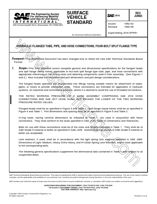
SAE Technical Standards Board Rules provide that: “This report is published by SAE to advance the state of technical and engineering sciences. The use of this report is entirely voluntary, and its applicability and suitability for any particular use, including any patent infringement arising therefrom, is the sole responsibility of the user.”SAE reviews each technical report at least every five years at which time it may be reaffirmed, revised, or cancelled. SAE invites your written comments and suggestions.QUESTIONS REGARDING THIS DOCUMENT: (724) 772-8512 FAX: (724) 776-0243TO PLACE A DOCUMENT ORDER; (724) 776-4970 FAX: (724) 776-0790SAE WEB ADDRESS 2.1.1SAE P UBLICATIONS —Available from SAE, 400 Commonwealth Drive, Warrendale, PA 15096-0001.SAE J120—Rubber Rings for Automotive ApplicationsSAE J429—Mechanical and Material Requirements for Externally Threaded Fasteners SAE J489—Lock Washers SAE J517—Hydraulic HoseSAE J846—Coding Systems for Identification of Fluid Conductors and Connectors2.1.2ASTM P UBLICATION —Available from ASTM, 100 Barr Harbor Drive, West Conshohocken, PA 19428-2959.ASTM B 117—Method of Salt Spray (Fog) Testing3.Size Designation—Four-bolt split flange connection sizes are designated by the nominal flange size which corresponds to the maximum inside diameter of the hole through the flanged head.4.Dimensions and Tolerances—Tabulated dimensions and tolerances shall apply to the finished parts, plated or otherwise processed, as specified by the purchaser. Tolerances on all dimensions for flanged heads, split flange clamp halves, and ports not otherwise limited shall be ±0.4 mm (0.016 in).5.Material—Flanged heads shall be made of steel. Split flange clamp halves shall be made from a material with the properties in Table 3.6.Finish—The external surfaces and threads of all carbon steel parts shall be plated or coated with a suitable material that passes a 72 h salt spray test in accordance with ASTM B 117. Any appearance of red rust during the 72 h salt spray test shall be considered failure, except for the following:a.All internal fluid passages.b.Edges such as hex points, serrations, and crests of threads where there may be mechanicaldeformation of the plating or coating typical of mass-produced parts or shipping effects.c.Areas where there is mechanical deformation of the plating or coating caused by crimping, flaring,bending, and other post-plate metal forming operations.d.Areas where the parts are suspended or affixed in the test chamber where condensate canaccumulate.NOTE—Cadmium plating is not preferred due to environmental reasons. Parts manufactured to this Standardafter January 1, 1997, shall not be cadmium plated. Internal fluid passages shall be protected from corrosion during storage. Changes in plating may affect assembly torques and require requalification,when applicable.Bolts shall be finished with a suitable coating that meet the previous requirements after a 16 h salt spray test in accordance with ASTM B 117. Lock washers may have a plain (natural) finish or a suitable coating..sa e-f l an g e.co m.s ae-f l an ge.co mFIGURE 1—ASSEMBLED SPLIT FLANGED CONNECTIONFIGURE 2—O-RING SEAL.sa e-f l an g e.co mFIGURE 3—FLANGED HEAD.sa e-f l an g e.co mFIGURE 4—SPLIT FLANGE CLAMP HALF (1101XX).sa e-f l an g e.co mFIGURE 5—PORT DIMENSIONS FOR HYDRAULIC FLANGED, TUBE, PIPE,AND HOSE CONNECTIONS, FOUR-BOLT SPLIT FLANGE TYPE.sa e-f l an g e.co mSize, inDash Size Max mm Max inDia mm Dia in ± 0.25mm ± 0.010in ± 0.25mm ± 0.010in ± 0.13mm ± 0.005in ± 0.13mm ± 0.005in 1/2 −8 130.5025.53- 25.40 1.005-1.000 30.18 1.188 30.96 1.219 6.730.265 6.220.2453/4−12 190.75 31.88- 31.75 1.255-1.250 38.10 1.500 38.89 1.531 6.730.265 6.220.2451−16 25 1.00 39.75- 39.62 1.565-1.560 44.45 1.750 45.24 1.781 8.000.3157.490.2951-1/4−20 32 1.25 44.58- 44.45 1.755-1.750 50.80 2.000 51.59 2.031 8.000.3157.490.2951-1/2−24 38 1.5053.98- 53.72 2.125-2.115 60.33 2.375 61.09 2.406 8.000.3157.490.2952−32 51 2.00 63.50- 63.25 2.500-2.490 71.42 2.812 72.24 2.844 9.530.3759.020.3552-1/2−4064 2.50 76.33- 76.07 3.005-2.995 84.123.312 84.94 3.344 9.530.3759.020.355348 76 3.0092.08- 91.823.625-3.615101.604.000102.39 4.031 9.530.3759.020.3553-1/2−56 89 3.50104.52-104.01 4.115-4.095114.30 4.500115.09 4.53111.230.42210.720.4224−64102 4.00117.22-116.71 4.615-4.595127.00 5.000127.79 5.03111.230.44210.720.4225−80127 5.00142.62-142.115.615-5.595152.406.000153.196.03111.230.44210.720.422Nominal Flange Size,in G Dia Max mm G Dia Max in H Dia Max mm H Dia Max in J Dia ± 0.25mm J Dia ± 0.010in K Ref mm K Ref inL ID Ref mmL ID Ref in M OD Ref mm M OD Ref in N Dia Ref mm N Dia Ref in O-Ring Size No.1/2 140.56 240.94 24.260.955130.5018.640.734 25.70 1.012 3.530.1392103/4 210.81 32 1.25 32.13 1.265140.5624.990.984 32.05 1.262 3.530.1392141 27 1.06 38 1.50 38.48 1.515140.5632.921.296 39.98 1.574 3.530.1392191-1/4 33 1.31 43 1.70 43.69 1.720140.5637.69 1.484 44.75 1.762 3.530.1392221-1/2 40 1.56 50 1.98 50.80 2.000160.62 47.22 1.859 54.282.1373.530.1392252 52 2.06 62 2.45 62.74 2.470160.62 56.74 2.234 63.802.5123.530.1392282-1/2 65 2.56 74 2.92 74.93 2.950180.69 69.44 2.734 76.503.0123.530.1392323 78 3.06 903.55 90.93 3.580190.75 85.32 3.359 92.383.637 3.530.1392373-1/2 90 3.561024.00102.36 4.030220.88 98.02 3.859105.08 4.137 3.530.1392414103 4.06114 4.50115.06 4.53025 1.00110.72 4.359117.78 4.6373.530.13924551295.061405.50140.465.530281.12136.125.359143.185.6373.530.139253Nominal Flange Size,in O mm O in P ± 0.8mm P ± 0.03in Q ± 0.25mm Q ± 0.010in R mm R in S Rad mm S Rad in T Dia ± 0.25mm T Dia ± 0.010in U mm U in V mm V in 1/2 54.9- 53.1 2.16-2.0921.80.86 38.10 1.500 80.31 80.31 8.740.344130.50190.753/4 65.8- 64.3 2.59-2.5324.90.98 47.63 1.875100.40 90.3410.310.406140.56220.781 70.6- 69.1 2.78-2.7228.2 1.11 52.37 2.062120.48 90.3410.310.406160.62240.941-1/4 80.3- 78.5 3.16-3.0935.3 1.39 58.72 2.312140.56100.4111.910.469140.56220.881-1/2 94.5- 93.0 3.72-3.6640.1 1.58 69.85 2.750170.67120.4713.490.531160.6225 1.002103.1-100.1 4.06-3.9447.2 1.86 77.77 3.062210.81120.4713.490.531160.6226 1.032-1/2115.8-112.8 4.56-4.4453.1 2.09 88.90 3.500240.96130.5013.490.531190.7538 1.503136.7-133.4 5.38-5.2564.3 2.53106.38 4.18830 1.18140.5616.660.656220.8841 1.623-1/2153.9-150.9 6.06-5.9468.6 2.70120.65 4.75034 1.34160.6216.660.656220.8828 1.124163.6-160.3 6.44-6.3174.9 2.95130.18 5.12538 1.49160.6216.660.65625 1.0035 1.385185.7-182.67.31-7.1989.43.52152.406.000451.78160.6216.660.656281.12411.62.sa e-f l an g e.co mFlange Size,in Bolt Dimensions Thread Dimensions Length mmDimensions Length inW ± 0.25mm W ± 0.010in X ± 0.25mm X ± 0.010in Working Pressure MPa Working Pressure psi Torque Range N·m Torque Range lb-in 1/25/16–18321-1/419.050.750 8.740.34434.55000 20– 25 175– 2253/43/8–16321-1/423.830.93811.130.43834.55000 28– 40 250– 35013/8–16321-1/426.19 1.03113.080.51534.55000 37– 48 325– 4251-1/47/16–14381-1/229.36 1.15615.090.59427.64000 48– 62 425– 5501-1/21/2–13381-1/234.93 1.37517.860.70320.73000 62– 79 550– 70021/2–13381-1/238.891.53121.440.84420.73000 73– 90 650– 8002-1/21/2–13441-3/444.45 1.75025.40 1.00017.22500107–124 950–110035/8–11441-3/453.192.09430.96 1.21913.82000186–2031650–18003-1/25/8–1151260.33 2.37534.931.3753.4 500158–1811400–160045/8–1151265.07 2.56238.891.5313.4 500158–1811400–160055/8–11572-1/476.20 3.00046.021.8123.4500158–1811400–1600TABLE 1B—DIMENSIONS OF HYDRAULIC FLANGED CONNECTIONS, HIGH PRESSURE SERIES (CODE 62)Nominal Flange Size, in Flange Dash Size A Dia Max mm A Dia Max in B Dia mmB Dia inC Dia ± 0.25mm C Dia ± 0.010inD Dia ± 0.25mm D Dia ± 0.010inE ± 0.13mm E ± 0.005inF ± 0.13mm F ± 0.005in 1/2 −8130.5025.53–25.40 1.005-1.00031.75 1.25032.54 1.2817.750.3057.240.2853/4−12190.7531.88-31.75 1.255-1.25041.28 1.62542.06 1.6568.760.3458.260.3251−1625 1.0039.75-39.62 1.565-1.56047.63 1.87548.41 1.9069.530.3759.020.3551-1/4−2032 1.2544.58-44.45 1.755-1.75053.98 2.12554.76 2.15610.290.4059.780.3851-1/2−2438 1.5053.98-53.72 2.125-2.11563.50 2.50064.29 2.53112.570.49512.070.4752−32512.0063.50-63.252.500-2.49079.383.12580.163.15612.570.49512.070.475Nominal Flange Size,in G Dia Max mm G Dia Max in H Dia Max mm H Dia Max in J Dia ± 0.25mm J Dia ± 0.010in K Ref mmK Ref in L ID Ref mm L ID Ref in M OD Ref mmM OD Ref inN Dia Ref mmN Dia Ref in O-Ring Size No.1/2 140.56240.9424.640.970140.5618.640.73425.70 1.012 3.530.1392103/4 210.8132 1.2532.51 1.280180.6924.990.98432.05 1.262 3.530.1392141 27 1.0638 1.5038.86 1.530210.8132.92 1.29639.98 1.574 3.530.1392191-1/4 33 1.3144 1.7244.45 1.75025 1.0037.69 1.48444.75 1.762 3.530.1392221-1/2 40 1.5651 2.0051.56 2.03030 1.1947.22 1.85954.28 2.137 3.530.1392252522.06672.6267.562.660381.5056.742.23463.802.5123.530.139228Nominal Flange Size,in O mm O in P ± 0.8mm P ± 0.03in Q ± 0.25mm Q ± 0.010in R mm R in S Rad mm S Rad in T Dia ± 0.25mm T Dia ± 0.010in U mm U in V mm V in 1/2 57.2- 55.6 2.25-2.1922.60.8940.49 1.594 80.32 80.31 8.740.344160.62220.883/4 72.1- 70.6 2.84-2.7829.0 1.1450.80 2.000110.43100.4110.310.406190.7528 1.121 81.8- 80.3 3.22-3.1633.8 1.3357.15 2.250130.51120.4711.910.469240.9433 1.311-1/4 96.0- 94.5 3.78-3.7237.6 1.4866.68 2.625150.59140.5613.490.53127 1.0638 1.501-1/2114.3-111.3 4.50-4.3846.5 1.8379.38 3.125170.68170.6616.660.65630 1.1943 1.692134.9-131.85.31-5.1955.92.2096.823.812210.84180.7219.840.781371.44522.06.sa e-f l an g e.co mFlange Size,in Bolt Dimensions Thread Dimensions Length mmDimensions Length inW ± 0.25mm W ±0.010in X ±0.25mm X ±0.010in Working Pressure MPa Working Pressure psi Torque Range N-m Torque Range lb-in 1/25/16–18321-1/420.240.797 9.120.35941.46000 20 –25 175 –2253/43/8–16381-1/225.40 1.00011.910.46941.46000 34 –45 300 –40017/16-14441-3/428.581.12513.890.54741.46000 56– 68 500– 6001-1/41/2–13441-3/433.32 1.31215.880.62541.46000 85–102 750– 9001-1/25/8–11572-1/439.67 1.56218.260.71941.46000158–1811400–160023/4–10702-3/448.411.90622.230.87541.46000271–2942400–2600TABLE 2A—PORT DIMENSIONS FOR BOLTED FLANGE CONNECTIONS, STANDARD PRESSURE SERIESNominal Flange Size,in Flange Dash Size A Dia + 0.0−1.5mm A Dia + 0.00−0.06in O mm O inFF mm FF inQ ± 0.25mmQ ± 0.010in GG ± 0.25mm GG ± 0.010in S Rad mm S Rad in W mm W in 1/2 −812.70.50 54 2.12 46 1.81 38.10 1.50017.480.688 80.31190.753/4−1219.10.75 65 2.56 52 2.06 47.63 1.87522.230.875 90.34240.941−1625.4 1.00 70 2.75 59 2.31 52.37 2.06226.19 1.031 90.3426 1.031-1/4−2031.8 1.25 79 3.12 73 2.88 58.72 2.31230.18 1.188100.4129 1.161-1/2−2438.1 1.50 94 3.69 83 3.25 69.85 2.75035.71 1.406120.4735 1.382−3250.8 2.00102 4.00 97 3.81 77.77 3.06242.88 1.688120.4739 1.532-1/2−4063.5 2.50114 4.50109 4.28 88.90 3.50050.802.000130.5044 1.753−4876.2 3.00135 5.31131 5.16106.38 4.18861.93 2.438140.5653 2.093-1/2−5688.9 3.50152 6.00140 5.50120.65 4.75069.85 2.750160.6260 2.384−64101.6 4.00162 6.38152 6.00130.18 5.12577.77 3.062160.6265 2.565−80127.05.001847.251817.12152.406.00092.08 3.625160.62763.00Nominal Flange Size,in X mm X in Y Rad mm Y Rad mm Z Thread UNC-2B AA Min mm AA Min mmBB (1)Min mm 1.Dimensions BB, CC, and DD provide 1.5 mm (0.06 in) clearance between flanges, dimensionally on the high limit, when, the same size flanges are used on adjacent ports. These dimensions do not apply when more than one size of flanges are used on adjacent ports.BB 1Min in CC 1Min mm CC 1Min in DD 1Min mm DD 1Min in EE Min mm EE Min in 1/2 90.34230.915/16–18240.94 56 2.22 52 2.06 49 1.91 33 1.313/4110.4426 1.033/8–16220.88 68 2.66 61 2.41 55 2.16 41 1.621130.5229 1.163/8–16220.88 72 2.84 67 2.62 61 2.41 48 1.881-1/4150.5937 1.447/16-1428 1.12 82 3.22 78 3.09 75 2.97 54 2.121-1/2180.7041 1.621/2-1327 1.06 96 3.78 90 3.56 85 3.34 64 2.502210.8449 1.911/2–1327 1.06104 4.09102 4.00 99 3.91 76 3.002-1/225 1.0054 2.141/2–1330 1.19117 4.59114 4.50111 4.38 89 3.50331 1.2266 2.585/8–1130 1.19137 5.41136 5.34133 5.25106 4.193-1/235 1.3870 2.755/8–1133 1.31155 6.09148 5.84142 5.59119 4.69439 1.5376 3.005/8–1130 1.19164 6.47160 6.28155 6.09132 5.195461.81903.565/8–11331.311867.341857.281837.221516.19.sa e-f l an g e.co m-11-8.Notes8.1Marginal Indicia—The change bar (l) located in the left margin is for the convenience of the user in locating areas where technical revisions have been made to the previous issue of the report. An (R) symbol to the left of the document title indicates a complete revision of the report.PREPARED BY THE SAE FLUID CONDUCTORS AND CONNECTORS TECHNICAL COMMITTEE SC2—HYDRAULIC HOSE AND HOSE FITTINGSSize,in Dash Size−1.5mm −0.06in O mm O in FF mm FF in ± 0.25mm ± 0.010in ± 0.25mm ± 0.010in Rad mm Rad in W mm W in 1/2 −812.70.50 56 2.22 48 1.8840.49 1.59418.240.718 80.31200.803/4−1219.10.75 71 2.81 60 2.3850.80 2.00023.800.937100.4125 1.001−1625.4 1.00 81 3.19 70 2.7557.15 2.25027.76 1.093120.4728 1.121–1/4−2031.8 1.25 95 3.75 78 3.0666.68 2.62531.75 1.250140.5633 1.311–1/2−2438.1 1.50113 4.44 953.7579.38 3.12536.50 1.437170.6640 1.562−3250.82.001335.251144.5096.823.81244.451.750180.72491.91Nominal Flange Size,in X mm X in Y Rad mm Y Rad in Z Thread UNC-2BAA Min mm AA Min inBB (1)Min mm 1.Dimensions BB, CC, and DD provide 1.5 mm (0.06 in) clearance between flanges, dimensionally on the high limit, when the same size flanges are used on adjacent ports. These dimensions do not apply when more than one size of flanges are used on adjacent ports.BB 1Min in CC 1Min mm CC 1Min in DD 1Min mm DD 1Min in EE Min mm EE Min in 1/2 90.36 240.945/16–18210.8159 2.34 56 2.22 53 2.09 38 1.503/4 120.47 30 1.193/8–16240.94752.94702.75 66 2.59 48 1.881 140.55 35 1.387/16–1427 1.06843.31803.16 75 2.97 54 2.121–1/4 160.62 39 1.531/2–1325 1.00 993.88903.56 83 3.25 60 2.381–1/2 180.72 48 1.885/8–1135 1.381164.561084.25101 3.97 70 2.752 220.88572.253/4–10381.501375.381285.031204.72863.38TABLE 3—MATERIAL PROPERTIESStandard series — 1/2 in (−8) size Minimum yield, 221 MPa (32 000 psi)Minimum elongation, 3%All other sizes Minimum yield, 414 MPa (60 000 psi)Minimum elongation, 3%High pressure series — all sizes Minimum yield, 331 MPa (48 000 psi)Minimum elongation, 3%.sa e-f l an g e.co mApplication—This SAE Standard covers complete general and dimensional specifications for the flangedheads and split flange clamp halves applicable to four-bolt split flange type tube, pipe, and hose connections with appropriate references to the O-ring seals and attaching components used in their assembly. (See Figures 1 and 2). Also included are recommended port dimensions and port design considerations.The flanged heads specified are incorporated into fittings having suitable means for attachment to tubes,pipes, or hoses to provide connection ends. These connections are intended for application in hydraulic systems, on industrial and commercial products, where it is desired to avoid the use of threaded connections.T HE RA TED WORKING PRESSURE OF A HOSE ASSEMBL Y COMPRISING SAE J518 HOSE CONNECTIONSAND SAE J517 HOSE SHALL NOT EXCEED THE LOWER OF THE TWO WORKING PRESSURE RA TED VALUES .Flanged heads shall be as specified in Figure 3 and Table 1. Split flange clamp halves shall be as specified in Figure 4 and Table 1. Port dimensions and spacing shall be as specified in Figure 5 and Table 2.O-ring seals, having nominal dimensions as indicated in Table 1, are used in conjunction with these connections. They shall conform to the seals specified in SAE J120, Table on Dimensions and Tolerances.Bolts for use with these connections shall be of the sizes and lengths indicated in Table 1. They shall be of SAE Grade 5 material or better as specified in SAE J429. Socket head cap screws of SAE Grade 5material or better are acceptable.Lock washers, if used, shall be in accordance with the light spring lock washers specified in SAE J489,Dimensions of Light, Medium, Heavy, Extra Heavy, and Hi Collar Spring Lock Washers, and of sizes applicable to the corresponding bolts.The following general specifications supplement the dimensional data contained in Table 1 with respect to all unspecified detail.Reference SectionSAE J120—Rubber Rings for Automotive ApplicationsSAE J429—Mechanical and Material Requirements for Externally Threaded Fasteners SAE J489—Lock Washers SAE J517—Hydraulic HoseSAE J846—Coding Systems for Identification of Fluid Conductors and Connectors ASTM B 117—Method of Salt Spray (Fog) Testing.sa e-f l an g e.co m.s ae-f l an ge.co m。
机械英语试题及答案高中
机械英语试题及答案高中一、选择题(每题2分,共20分)1. The machine is designed to operate at high ________.A. speedB. pressureC. efficiencyD. temperature答案:B2. The ________ of the engine is crucial for its performance.A. maintenanceB. designC. structureD. material答案:A3. The ________ of the gearbox is to transfer power from the engine to the wheels.A. functionB. purposeC. mechanismD. process答案:A4. The ________ of this machine is to reduce the noise level.A. featureB. characteristicC. advantageD. benefit答案:A5. The robot arm is controlled by a ________ system.A. hydraulicB. pneumaticC. electronicD. manual答案:C6. The ________ of the engine is measured in revolutions per minute (RPM).A. speedB. efficiencyC. powerD. torque答案:A7. The ________ of the machine is essential for its stability.A. balanceB. weightC. sizeD. shape答案:A8. The ________ is used to cut metal in a precise manner.A. latheB. drillC. sawD. grinder答案:C9. The ________ is responsible for the movement of the machine.A. motorB. controllerC. sensorD. actuator答案:D10. The ________ is a device that converts electrical energy into mechanical energy.A. batteryB. generatorC. transformerD. motor答案:D二、填空题(每题2分,共20分)1. The ________ of the machine is to ensure that it operates within safe parameters.答案:safety system2. The ________ is the part of the machine that provides the necessary force to perform work.答案:actuator3. The ________ is used to measure the temperature of the machine's components.答案:thermometer4. The ________ is a type of machine that can perform complextasks without human intervention.答案:robot5. The ________ is a device that controls the flow of fluids in a hydraulic system.答案:valve6. The ________ is a type of machine that uses compressed air to operate.答案:pneumatic system7. The ________ is a device that converts mechanical energy into electrical energy.答案:generator8. The ________ is a device that measures the force exerted on an object.答案:load cell9. The ________ is a type of machine that can be programmed to perform specific tasks.答案:automated machine10. The ________ is a device that controls the speed and direction of a motor.答案:controller三、简答题(每题10分,共30分)1. 描述一下什么是机械传动系统,并举例说明其在机械中的应用。
机械英语试题及答案详解
机械英语试题及答案详解一、选择题1. The term "mechanical engineering" refers to the application of engineering principles to:A. Chemical processesB. Electrical systemsC. Design and manufacture of machinesD. Software development答案:C2. What is the primary function of a bearing in a mechanical system?A. To convert energyB. To reduce frictionC. To increase efficiencyD. To absorb heat答案:B3. The process of converting a rough workpiece into a finished part is known as:A. MachiningB. WeldingC. CastingD. Forging答案:A二、填空题4. The formula for calculating the force exerted by a springis known as ________.答案:Hooke's Law5. In mechanical design, the term ________ refers to thestudy of the forces and moments acting on a body.答案:Statics6. The unit of pressure in the International System of Units (SI) is ________.答案:Pascal (Pa)三、简答题7. Explain the difference between static and dynamic friction.答案:Static friction is the force that must be overcometo start moving an object at rest, while dynamic friction is the force that opposes the motion of an object that isalready moving.8. Describe the purpose of a gear in a mechanical system.答案:A gear is used to transmit motion and force from one part of a system to another, often changing the speed and/or direction of the motion.四、计算题9. A hydraulic press has a piston with an area of 0.02 m². If the pressure applied to the piston is 5 MPa, calculate the force exerted by the piston.答案:Force = P ressure × Area = 5 × 10⁶ Pa × 0.02 m²= 100,000 N10. A lever is balanced when the product of the effort force and its distance from the fulcrum is equal to the product of the load force and its distance from the fulcrum. If the effort force is 300 N and the load force is 1200 N, and the effort is applied 2 m from the fulcrum, calculate the distance from the fulcrum to the load.答案:Let the distance from the fulcrum to the load be\( x \). According to the principle of levers, \( 300 N\times 2 m = 1200 N \times x \). Solving for \( x \) gives\( x = \frac{300 N \times 2 m}{1200 N} = 0.5 m \).五、论述题11. Discuss the importance of mechanical vibrations in the context of machinery operation and maintenance.答案:Mechanical vibrations are crucial in machinery for several reasons. They can indicate the health of a machine, with abnormal vibrations often signaling a problem such as imbalance, misalignment, or wear. Monitoring vibrations can help in predictive maintenance, preventing breakdowns and extending the life of machinery.12. Explain the concept of stress concentration in mechanical components and its implications.答案:Stress concentration occurs in mechanical components where the stress is higher than the average stress due to geometrical discontinuities or material defects. This can lead to premature failure of the component under load, as the high-stress areas are more susceptible to fatigue and cracking. Designing to minimize stress concentrations and using materials with good fatigue resistance can mitigate these effects.。
单齿辊式破碎机 毕业设计论文
单辊破碎机实际上是将颚式破碎机和辊式破碎机的部分结构组合在一起,因而具有这两种破碎机的特点,该机种又称为颚辊破碎机。单辊破碎机具有较大的进料口,另外辊子表面装有不同的破碎齿条,当大块物料喂入时,较高的齿条将大块物料钳住,并以劈裂和冲击方法将其破碎,然后落到下方,再由较小的齿将其进一步破碎到要求的尺寸。在一台破碎机中,有预碎区和二次破碎区,所以可用于粗碎物料,而且破碎比较大,可达!$。破碎时,料块受到辊子上的齿棱拨动而卸出机外,因此是强制卸料,粉碎粘湿的物料也不致发生堵塞。单辊破碎机宜用于粉碎中硬或松软的物料,如石灰石、硬质粘土及煤块等。当物料比较粘湿(如含土石灰石等)时,它的粉碎效果比使用颚式破碎机和圆锥破碎机都好,特别是对于破碎片状粘土物料,与颚式或圆锥破碎机相比,在性能与机体紧凑方面均有优越之处。单辊破碎机的规格是用辊子直径和长度来表示。
1.2
专业的矿山机械行业用的碎石机可分为:鄂式破碎机,锤式破碎机,复合式破碎机,辊式破碎机,冲击式破碎机,石头破碎机,反击式破碎机等。
1、鄂式破碎机:颚式破碎机具有破碎比大、产品粒度均匀、结构简单、工作可靠、维修简便、运营费用经济等特点。
2、锤式破碎机:(环锤式破碎机)简称:锤破,主要适用于破碎各种脆性材料的矿物。被破碎物料为煤、盐、白亚、石膏、明矾、砖、瓦、石灰石等。
另外随着工业自动化的发展,破碎机也向自动化方向迈进(如国外产品已实现机电液一体化、连续检测,并自动调节给料速率、排矿口尺寸及破碎力等)。随着开采规模的扩大,破碎机也在向大型化发展,如粗碎旋回破碎机的处理能力已达6000th。至于新原理和新方式的破碎(如电、热破碎)尚在研究试验中,暂时还不能用于生产。对粗碎而言,目前还没有研制出更新的设备以取代传统的颚式破碎机和旋回式破碎机,主要是利用现代技术,予以改进、完善和提高耐磨性,达到节能、高效、长寿的目的。细碎方面新机型更多些。总的来看,值得提出的有:颚式破碎机、圆锥破碎机、冲击式破碎机和辊压机。而应用最广泛的就是鄂式破碎机。
机械工程专业英语试卷A机答案
XXXX/第1学期期终试卷A(考试类型:闭卷)课程机械工程专业英语(参照答案及评分阐明) 班级姓名一、词汇(20分)(每个题目为2分)1:把下列英文单词翻译成中文:(1) threshold参照答案:开端,开始(2) graphics terminal参照答案:图像终端(3) a translate command参照答案:平移指令(4) construction robotics参照答案:建筑(构造)机器人(5) a power-driven device参照答案:力驱动装置2:把下列中文词组翻译成英文:(6) 热加工参照答案:hot working(7) 非正常晶体生长参照答案:abnormal grain growth(8)再结晶参照答案:recrystallization(9) 机械效益参照答案:mechanical advantage(10)力放大器参照答案:a force multiplier二、句型(20分)(每个题目为4分)(翻译旳内容,到达意思一致即算对旳)请将下列英文句子翻译成中文(1)Efficiency and mechanical advantage are used to gauge the performance of mechanical machine .参照答案:效率和机械效益是用来检测机械装置旳工作性能旳。
(2)Methods of extracting , producing and treating metals are being developed all the time to meet engineering requirements .参照答案:为了满足工程需要,提炼、生产和处理金属旳措施一直处在发展进步之中。
(3) The common metallic materials possess the metallic properties of luster , thermal conductivity, and electrical conductivity ;are relatively ductile;and some have good magnetic properties .参照答案:常见旳金属材料拥有旳金属性能如:光泽、导热性和导电性,并且有很好旳延展性,此外,尚有某些金属材料具有好旳磁性。
毕业设计论文 电子秤 中英文 外文资料 文献 翻译
外文参考资料二:Abstract: In order to solve the weight problem often encountered in measuring the low-mass objects in the trade and daily life of the modern business, the design of a new pocket-sized electronic scales. This pocket-sized electronic scales Force Sensor gravity signals into electrical signals to measure, and measuring the results of the digital display. The pocket-sized electronic scales with a small size, light weight, easy to carry, intuitive display, measurement and high precision; complex structure, the cost disadvantages. This article focuses on the load cell works, error compensation, the main parameters of selection. And the technical and economic analysis.Keywords: pocket-sized electronic scales; weighing; sensor; error compensationCLC number: TH715. 1] sign code: A Article ID: 100 522 895 (2007) 022*******1 A needs analysisIn modern commerce and trade and everyday life, often encounter the problem of measuring the weight of the low-mass objects. Although the traditional steelyard can solve this problem, but inconvenient to carry, the efficiency is not high, the display is not intuitive and low measurement accuracy; mechanical spring balance can solve this problem, but the inertia inherent low frequency, high sensitivity, measurement accuracy is not high. With the progress and update of the micro-computer technology, integrated circuit technology, sensor technology, electronic scales rapiddevelopment, it has a responsive, high accuracy, fully functional, the display is intuitive, compact, easy to use and so on.For these reasons, in order to solve the low-mass objects weighing problem, if a small size, light weight, portable, digital display electronic scales, will be popular. Discussed below, that is, the scope of a weighing 5 kg compact electronic scales.2 DesignThe principle of the structure of the pocket-sized electronic scales shown in Figure 1. The main task is to design compact electronic scales weighing the choice of the force sensors. Dynamometer sensor types to achieve the weighing and digital display, the key is to want to force (gravity) signals into electrical signals to measure method is mainly divided into two categories: one is the direct method, namely the use of pressure magnetic sensor, piezoelectric sensor, Piezoresistive sensors directly to the force signal converted into electrical signals; the other is the indirect method, the elastic element as the sensor will pull, pressure changes in strain, displacement, or frequency, and then strain sensors, displacement sensors, or frequency sensor strain, displacement or frequency changes for power. Comprehensive comparison of a variety of sensors, use the indirect method of strain gauge force transducer.Pocket-sized electronic scale structural principle:Sensor → amplifier → CPU→ display → AöD converter3 sensor device design3.1 worksThe working principle of the strain gauge force transducer strain gauge pasted into force, force-sensitive elasticelement, the corresponding strain when the elastic element force deformation, the strain gauge into a resistance change, which led to the voltage measuring circuit changes by measuring the output voltage value, and then through the conversion can be obtained by the measurement of body weight. Since the pocket-sized electronic scales require small size, weighing in scope, precision and angle even consistency, sensor and display integration, it is selected parallel to the two holes cantilever beam strain gauge load-bearing sensor. Its characteristics are: high precision, ease of processing, simple and compact structure, strong resistance to partial load, high natural frequency.Strain gauge choice of a metal palisade metal mooring paste on the insulating substrate parked strain gages, mechanical strain resistance strain gauge feelings generally 10 - 10 - 2mm, the resistance rate of change of the attendant about 10 - 6 10 - 2 orders of magnitude, such a small change in resistance measured using the general resistance of the instrument is hard to measure out, you must use some form of measurement.Circuit into small changes in resistance rates to changes in voltage or current, in order to secondary instrument display. Bridge measurement circuit to meet this requirement. In the load cell, R 1, R 2, R 3, R 44 strain gauge resistor bridge measurement circuit shown in Figure 3. R m is the temperature compensation resistor, e is the excitation voltage, V is the output voltage.外文参考资料三:The load cell is a quality signal into a measurable electrical signal outputdevice. Must consider the actual working environment of the sensor which sensor Yin, this is essential for the correct selection of the load cell, and it is related to the sensor can work as well as its safety and service life, and the whole weighing the reliability and safety sex. On the basic concepts and methods of evaluation of the major technical indicators of the load cell, the new and old GB qualitative differences.The traditional concept, the load sensor weighing sensors, force sensors, collectively referred to using a single parameter to evaluate its measurement properties. Old GB will be completely different application objects and the use of environmental conditions "weighing" and "measured force" two sensors into one to consider, not given to distinguish between the test and evaluation methods. Old GB total of 21 indicators, were tested at room temperature; and non-linearity, hysteresis error, repeatability error, creep, the additional error of the zero temperature and the maximum error in the six indicators of the rated output additional temperature error, to determine said The level of accuracy of the weight sensor, respectively 0.02,0.03,0.05 said.Proportion to convert the output signal can be measured. Taking into account the different place of use of the acceleration due to gravity and air buoyancy on the conversion, the main performance indicators of the load cell linearity error, hysteresis error, repeatability error, creep, zero-temperature characteristics and temperature sensitivity characteristics. In a variety of weighing and measuring the quality of the system, usually the integrated error accuracy of the integrated control sensors, and integrated error band or scale error band (Figure 1) linked so that selection corresponds to a certain accuracy weighing weighing sensors. International Organization of Legal Metrology(OIML) requirements, sensor error with total weighing instrument error δ with Δ of 70% of the load cell linearity error, hysteresis error within the specified temperature range due to the effect of temperature on the sensitivity of the error the sum can not exceed the error band of δ. This allows the manufacturer of the components that make up the total measurement error adjustment to obtain the desired accuracy.The load cell conversion method is divided into photoelectric, hydraulic, electromagnetic force type, capacitive, magnetic poles change the form of vibratory gyroscope ceremony, resistance strain type, to the most extensive use of resistance strain.Electromagnetic force sensorIt uses a load-bearing stage load and the principle of electromagnetic force Equilibrium (Figure 5). Put the loading stage, the measured object at one end of the lever upward tilt; photoelectric detect the tilt signal, amplified into the coil, the electromagnetic force, so that the lever to return to equilibrium. Currents produce electromagnetic counterweight digital converter, you can determine the quality of the measured object. The electromagnetic force sensor accuracy, up to 1/2000 ~ 1/60000, but the weighing range is only tens of mg to 10 kg.Capacitive sensorsItcapacitor oscillator circuit of the oscillation frequency f and the plate spacing d is directly proportional relationship between the work (Figure 6). There are two plates, one fixed and the other one can move. Bearing load measured object, the leaf spring deflection, the distance between the twoplates changes, the oscillation frequency of the circuit also changes. The measured frequency change can be calculated to the quality of the load-bearing stage, the measured object. Capacitive sensor power consumption, low cost, accuracy of 1/200 to 1/500.Pole change the form of sensorFerromagneticcomponents in the measured object gravity under mechanical deformation, internal stress and cause changes in permeability, and also changes so that the induced voltage of the secondary coil wound on both sides of the ferromagnetic component (pole). Measure the voltage variation can be calculated added to the force on the pole, and then determine the quality of the measured object. Pole to change the form of sensor accuracy is not high, usually 1/100, applicable to the large tonnage weighing, weighing ranging from tens to tens of thousands of kilograms.Vibration sensorThe force of the elastic element, the natural vibration frequency of the force is proportional to the square root of. Measure the natural frequency changes, you can find the measured object role in the elastic component of the force, and then calculate the quality. The vibration sensor vibrating wire and tuning fork.The elastic component of the vibrating wire sensor string wire. When the load-bearing stage, plus the measured object, the intersection of the V-shaped string wire is pulled down, and left strings of tension increases, the right string tension decreases. The natural frequency of the two strings of different changes. Calculate the frequency difference between the two strings, you can find the quality of the measured object. The higher the accuracy of the vibrating wire sensor, up to 1/1000 ~ 1/10000, weighing 100 g to hundreds of kilograms, but the structure is complex anddifficult process, and high cost.The elastic component of the tuning fork sensor is a tuning fork. Fixed tuning fork end of the piezoelectric element, the natural frequency of oscillation of a tuning fork, it can be measured oscillation frequency. When the load-bearing stage and the measured object, the tuning fork direction of tensile force while the increase in natural frequency, increasing levels of applied force is proportional to the square root. Measure the changes of natural frequency can be calculated heavy loads imposed on the tuning fork on the force, and then calculate the quality of heavy objects. The tuning fork sensor power consumption, measurement accuracy up to 1/10000 to 1/200 000, weighing range of 500g ~ 10kg.外文参考文献中文翻译参考资料二:摘要: 为解决现代商业贸易和日常生活中经常遇到的测量小质量物体的重量问题, 介绍了一种新型的袖珍式电子秤的设计。
机械英语考试试题及答案
机械英语考试试题及答案一、选择题(每题2分,共20分)1. The term "mechanical engineering" refers to:A. The study of machinesB. The design and manufacture of mechanical systemsC. The operation of machineryD. The maintenance of mechanical equipment答案:B2. What is the function of a bearing in a mechanical system?A. To reduce frictionB. To increase efficiencyC. To provide powerD. To transmit motion答案:A3. The process of converting thermal energy into mechanical energy is known as:A. ElectrificationB. CombustionC. ThermodynamicsD. Hydrodynamics答案:C4. In mechanical design, the principle of "KISS" stands for:A. Keep It Simple, StupidB. Keep It Short and SimpleC. Keep It Simple and SafeD. Keep It Simple, Smart答案:A5. A gear train is used to:A. Change the direction of motionB. Increase the speed of rotationC. Decrease the speed of rotationD. All of the above答案:D6. What does CAD stand for in mechanical engineering?A. Computer-Aided DesignB. Computer-Aided DraftingC. Computer-Aided DevelopmentD. Computer-Aided Diagnostics答案:A7. The SI unit for force is:A. NewtonB. JouleC. PascalD. Watt答案:A8. What is the purpose of a flywheel in a mechanical system?A. To store energyB. To increase speedC. To reduce noiseD. To dissipate heat答案:A9. The term "hydraulics" is associated with the study of:A. Fluid dynamicsB. Solid mechanicsC. Structural analysisD. Thermal engineering答案:A10. The process of cutting a material to a specific shape is known as:A. MachiningB. CastingC. ForgingD. Extrusion答案:A二、填空题(每空1分,共10分)11. The formula for calculating the moment of a force is \( F \times d \), where \( F \) is the force and \( d \) is the_______.答案:distance from the pivot12. A _______ is a device that converts linear motion into rotational motion.答案:crank13. In a four-stroke internal combustion engine, the four strokes are intake, compression, _______, and exhaust.答案:power14. The _______ of a material is its ability to resist deformation under load.答案:stiffness15. The term "overhaul" in mechanical maintenance refers to a thorough inspection and _______ of a machine or its parts.答案:repair16. The _______ of a machine is the study of how forces act on and within a body.答案: statics17. A _______ is a type of machine that uses a screw to convert rotational motion into linear motion.答案:screw jack18. The _______ of a system is the point around which the system rotates.答案:pivot19. The _______ of a lever is the ratio of the effort arm to the load arm.答案:mechanical advantage20. The _______ is a type of bearing that allows for rotation with minimal friction.答案:ball bearing三、简答题(每题5分,共30分)21. Explain the difference between static and dynamic equilibrium in mechanical systems.答案:Static equilibrium refers to a state where the net force and net moment acting on a body are zero, resulting in no acceleration. Dynamic equilibrium occurs when the net force is zero, but the body is in motion with constant velocity.22. What is the purpose of a clutch in a vehicle?答案:A clutch is used to engage and disengage the power transmission from the engine to the transmission system, allowing the vehicle to start, stop, and change gears smoothly.23. Describe the function of a governor in an engine.答案:A governor is a device that automatically controls the speed of an engine by regulating the fuel supply or the valve settings, ensuring the engine operates within safespeed limits.24. What are the three primary types of joints in structural engineering?答案:The three primary types of joints are pinned joints, fixed joints, and sliding joints, each serving different purposes in connecting and supporting structural elements.25. Explain the。
机械专业英语(章跃版)课后英汉翻译(最全)
第一章:应力与应变1.That branch of scientific analysis which motions, times and forces is called mechanics and is made up of two parts, statics and dynamics.研究位移、时间和力运动乘力是科学分析法的一个分歧,被称作力学,力学由两大部分组成,静力学和动力学。
2.For example, if the force operating on a sleeve bearing becomes too high, it will squeeze out the oil film and cause metal-to-metal contact, overheating and rapid failure of the bearing.例如:如果止推轴承上的作用力过大的话,会挤出油膜,引起金属和金属之间的相互接触,轴承将过热而迅速失效。
3.Our intuitive concept of force includes such ideas as place of application, direction, and magnitude, and these are called the characteristics of a force.力的直观概念包括力的作用点、大小、方向,这些被称为力的三要素。
4.All bodies are either elastic or plastic and will be deformed if acted upon by forces. When the deformation of such bodies is small, they are frequently assumed to be rigid, i.e., incapable of deformation, in order to simplify the analysis.所有的物体既可以是弹性的也可以是塑性的,如果受到力的作用就产生变形。
- 1、下载文档前请自行甄别文档内容的完整性,平台不提供额外的编辑、内容补充、找答案等附加服务。
- 2、"仅部分预览"的文档,不可在线预览部分如存在完整性等问题,可反馈申请退款(可完整预览的文档不适用该条件!)。
- 3、如文档侵犯您的权益,请联系客服反馈,我们会尽快为您处理(人工客服工作时间:9:00-18:30)。
I NSTITUTE OF P HYSICS P UBLISHING S UPERCONDUCTOR S CIENCE AND T ECHNOLOGY Supercond.Sci.Technol.16(2003)1077–1081PII:S0953-2048(03)62226-8Role of mechanical deformation in the texturing of coated conductor composites Y X Zhou,S Bhuiyan,S Scruggs,H Fang and K SalamaTexas Center for Superconductivity and Advanced Materials,University of Houston,Houston,TX77204,USAReceived8April2003,infinal form14July2003Published8August2003Online at /SUST/16/1077AbstractNi and Ni-based alloys have received considerable attention as the substratesfor HTS coated conductors.A critical step in the successful fabrication ofcoated conductor composites on metal substrates is to produce cube textureby mechanical deformation using the rolling assisted biaxial texturedsubstrate(RABiTS)approach.In this paper,we investigated the effects ofmechanical deformation and heat treatment on the growth of texture innickel and nickel–tungsten alloys with the objective of understandingmechanisms of mechanical texturing in coated conductor substrates.Theresults show that the sharpest cube texture is obtained by cold rolling nickeland nickel tungsten alloys in passes of less than5%deformation followedby annealing at high temperature.(Somefigures in this article are in colour only in the electronic version)1.IntroductionIt is well known that biaxially textured ReBCO is necessary to obtain high transport critical current densities.Therefore, practical applications using HTS have been hampered by difficulties in fabricating these brittle oxide materials into long biaxially texturedflexible wires capable of carrying large critical currents(J c).Thus,significant efforts have focused on studying crystallographic alignment in superconducting wires.In order to obtain a high transport J c,superconducting tape should ideally consist of a network of low angle grain boundaries[1].This has prompted extensive investigations into the development of the rolling assisted biaxially textured substrate(RABiTS)[2]process at Oak Ridge National Laboratory,IBAD(ion-beam assisted deposition)[3–5],and ISD(inclined substrate deposition)[6,7].Among them, RABiTS is a relatively simpler and more cost effective technique for the production of long lengths necessary for many applications.The aim of the RABiTS process is to fabricate biaxially textured metal substrates,which involves a number of steps, namely,preparation of the polycrystalline metal,mechanical deformation of the metal and recrystallization of the deformed metal[8].When a polycrystalline metal is plastically deformed,the lattice orientation of the individual grain is altered towards a preferred orientation in which certain lattice directions are aligned with the principal directions of plastic flow in the metal.The actual orientation distribution of grains is termed deformation texture.When such a material is recrystallized it acquires a texture,which may be identical to the previous deformation texture but more often is quite different.Nickel and Ni-based alloys have become the substrate of choice for coated conductors because they form a very strong cube texture after mechanical deformation texturing and recrystallization.In addition,they have comparatively better resistance to oxidation,better chemical compatibility and small lattice and thermal mismatch with diffusion barriers such as yttria stabilized zirconia(YSZ)or cerium oxide which allows epitaxial growth of the buffer and HTSfilms[9–12].The potential for further improvement in the performance of such substrates has been increased by the production of even higher quality textured Ni and Ni alloy substrates;for example,groups have produced Ni substrates with FWHM φ=10◦–15◦and ω=7◦–9◦(Gladstone et al[13]), φ=8◦–10◦, ω=8◦–10◦(Truchan et al[14]) and φ=6◦, ω=7◦(Goyal et al[2]).In addition,Goyal et al[8]have studied Ni–W,Ni–Cr,Ni–Al,Ni–Cu and Ni–W–Al alloy substrates.These alloy substrates have reduced magnetism and have significantly increased yield strength and ultimate tensile strength,with φ=7◦–10◦, ω=6◦–8◦.In this paper,we have developed a mechanical deformation texturing method to fabricate biaxially textured sheets of Ni and Ni-based alloy substrates with desirable compositions.We also investigated the effects of mechanical0953-2048/03/091077+05$30.00©2003IOP Publishing Ltd Printed in the UK1077Y X Zhou et aldeformation and heat treatment on the growth of texture in nickel and nickel tungsten alloys with the objective of understanding mechanisms of mechanical texturing in coated conductor substrates.2.Experimental detailsFor Ni substrates,the starting material was very pure nickel 99.995%obtained from Alfa Aesar.The powder-in-tube method was used to fabricate the Ni3at%W alloy,using 99.99%purity starting Ni and W powders from Alfa Aesar. First,97at%Ni and3at%W powders were milled withagate pestle and mortar for90min,then packed in a rubber tube,CIPed and sintered to fabricate the Ni–W alloy.The Ni strips were mechanically deformed to obtain various thicknesses of(0.24,0.18and0.1mm)tape.Three values of average deformation reduction per pass,2%,5%and 10%,were used in this work.After the rolling procedure, each of the deformed tapes is cut into small pieces for heat treatment at1000◦C for90min(details in[15]),which was performed using a tube furnace in reducing atmosphere consisting of a mixture of5%H2in argon.The Ni–W alloy substrate was fabricated using almost the same conditions which produced optimal texturing of pure Ni except the higher annealing temperature to form the uniform Ni–W alloy.Deformation texturing properties were characterized by a Siemens D5000series x-ray diffractometer for the purpose of measuring the Bragg diffraction angle2θdetermined by θ–2θscans for the textured samples.The sharpness of the texture was measured using x-ray rocking curves.A Siemens general area detector diffraction system(GADDS)with a polefigure goniometer was used to obtain polefigure measurements.The polefigure is a stereographic projection, which shows the distribution of a particular crystallographic direction in the assembly of grains that constitutes the specimen.Finally,JOEL JSM6330-F,an enhanced SEM-based technique system,was also used to perform the texture analysis on the samples.3.Results and discussions3.1.Effects of mechanical deformationFigure1shows the XRDθ–2θscan for the as-received nickel samples,after mechanical deformation and annealing.After mechanical deformation,it can be seen that deformation texture has developed.During the mechanical deformation, plasticflow causes a reorientation of the lattice of individual grains and the development of a texture or preferred orientation of the lattice in the grains.The progress of reorientation is gradual;orientation change proceeds as plasticflow continues, until a texture is reached against indefinitely continuedflow of given type.The nature of stable deformation texture and the manner in which it is approached are characteristic of the material and the nature of theflow throughout the deformation process(the magnitude of the three principal strains at all points within the specimen and at successive times in the process).The significant point from this20406080(220)(200)(111)Before rolling2 Theta angle (degrees)(220)(200)(111)After rolling(200)After annealingIntensity(counts)Figure1.XRD scans for the as-received undeformed,after mechanical deformation and after annealing,nickel samples.figure is the abnormally high peak{002}and the almost complete suppression of other peaks in the annealed sample. This implies that the nickel has been preferentially textured. Also,from thisfigure it can be deduced that nickel with a sharp in-plane cube texture can be processed using this thermomechanical method.3.2.Effects of deformation per passTo study the effect of the reduction per pass on pure nickel, samples were mechanically deformed using three values of deformation per pass,namely,2%,5%and10%.Thefinal thickness reached in each sample was about0.1mm giving a total reduction of95%.The samples were then annealed at 1000◦C for90min.Figure2shows(111)polefigures for these Ni samples.For higher values of deformation per pass, significant amount of retained texture is present.Even with5% deformation per pass,the substrate still presents a large amount of retained texture.Small components of untextured materials can result in a significant fraction of undesirable high-angle grain boundaries as has been determined by electron back scatter Kikuchi diffraction[16].From the above study, it is determined that lower reductions per pass are more conducive to developing higher degrees of cube texture in the Ni tapes.In general,longitudinal as well as lateral spread was observed during mechanical deformation.In order to minimize lateral spread,the tape was held in tension while mechanically deformed;however,a substantial amount of lateral spread was still observed and was found to increase considerably with larger values of reduction per pass.One of the implications of lateral spread is that the direction of materialflow during mechanical deformation is no longer unidirectional.To obtain pure cube textured substrate after recrystallization,it is essential to have a uniaxial deformation during mechanical deformation treatment.Thus the amount of lateral spread,which depends on the deformation per pass used during mechanical deformation strongly influences the quality of the cube texture obtained after recrystallization.1078Role of mechanical deformation in the texturing of coated conductorcomposites(a) (c)(b)Figure2.(111)polefigures of mechanically deformed Ni substrate with(a)2%,(b)5%and(c)10%deformation per pass annealed at 1000◦C/90min.Figure3.(111)polefigures of mechanically deformed Ni substrate with(a)95%,(b)90%and(c)88%total deformation annealed at 1000◦C/90min.3.3.Effects of total deformationFor this study,samples with an initial gauge thickness of 2mm were cold rolled to thicknesses of0.24mm,0.18mm and0.1mm successively.The total reduction attained in each case was88%,91%and95%.A reduction rate of2% per pass was used to achieve the desired thickness in each sample.The samples were then annealed at1000◦C for about90min.Figure3shows(111)polefigures for these Ni samples.For a lower percentage of total deformation, a significant amount of retained texture was present.Even with90%total deformation,the substrate still presents a large amount of retained texture.For the sample with95%total deformation,only the peaks corresponding to the{100} 100 cube orientations can be seen in the polefigures indicating a sharp textured material.3.4.Mechanical deformation of Ni substrateAccording to the above studies,RABiTS requires careful optimization of mechanical deformation to achieve a sharp cube texture with few misaligned grains.Our work indicates that,with a deformation rate of2%per pass and total deformation of95%,one can obtain sharp cube textured substrates.Figure4shows x-rayφ-scans andω-scans for mechanically deformed textured Ni substrates with2% deformation per pass and total deformation larger than95% annealed at1000◦C for90min.The values of full width at half maximum for these substrates were6.9◦and6.1◦for in-plane and out-of-plane respectively.For these samples,the surface roughness and the microstructure were studied. The quality of the substrate surface is primarily dependent on the quality of the rolls used.For the scale-up to continuous production of coated conductors,it would be ideal if no polishing steps were needed.If polishing is to be avoided, grain boundary grooving during annealing must be minimized. Figure5(a)shows a SEM image where the grains are distinctly separated by grain-boundary grooves;however,both the depth and width of the grooves are very small,indicating the annealing temperature and holding time are reasonable. Figure5(b)shows AFM image of the Ni substrate.Roughness value(R rms)is about0.343nm calculated over an area of 1µm2which was selected randomly from the sample surface. The rms(root mean square)roughness is a very simple measure of the height profile roughness.The rms roughness describes thefluctuations of surface heights around an average surface height.This roughness indicates the surfaces of the mechanically deformed textured Ni substrates are suitable enough for further deposition of buffer layers.3.5.Mechanical deformation textured Ni–W alloy substrate The Ni3at%W alloy strip is mechanically deformed by rolling to a degree greater than95%total deformation using about2% reduction per pass and reversing the rolling direction during each subsequent pass.It is annealed at about1200◦C for about90min to produce a sharp biaxial texture.Annealing is performed inflowing4%H2in Ar.Figure6shows a (111)x-ray diffraction polefigure of the biaxially textured1079Y X Zhou et al-50 0 50 100 150 200 250 300 35050100150200c o u n tφNi (111)FWHM=6.9oθ10 1520 25 303540C o u n t s(b )(a )Figure 4.X-ray (a )φ-scans and (b )ω-scan for mechanical deformation textured Ni substrate.R rms =0.343nm(b )(a )500nmFigure 5.(a )SEM and (b )AFM micrograph of mechanical deformation textured Ni substrate.alloy substrate.As can be seen,only four peaks are evident.Each peak refers to one of four crystallographically similarFigure 6.X-ray (111)pole figure of mechanical deformation textured Ni–W alloy substrate.0500100015002000250030003500-300-200-1000100Phi ScansC o u n t sFigure 7.X-ray φ-scans for mechanical deformation textured Ni–W alloy substrate.Rocking Curve of Ni-W Substrate 02000040000600008000010000010203040The taC o u n t sFigure 8.X-ray ω-scans for mechanical deformation textured Ni–W alloy substrate.orientations corresponding to {100} 100 ,such that the (100)plane is parallel to the surface of the tape and 100 direction is aligned along the length of the tape.Figure 7shows a φ-scan of the [111]reflection showing the degree of in-plane texture.The FWHM of the tape is about 7.5◦determined by fitting a Gaussian curve to the data.Figure 8shows the rocking curve or the out-of-plane texture as measured by scanning the [200]reflection of the substrate.It is a rocking curve with the sample being rocked in the rolling direction and shows a FWHM of 4.5◦.This is truly a single orientation texture with all crystallographic axes being aligned in all directions within 8◦.Together,these results indicate that using our thermomechanical processing,we can obtain sharp texturing in Ni–W alloy substrates.1080Role of mechanical deformation in the texturing of coated conductor composites4.SummaryA study regarding the role of mechanical deformation in texturing of coated conductor composites has been carried out.Mechanical deformation per pass and total deformation have determinant roles on texturing of Ni substrate.The degree of cube texture increases with increasing percentage of total mechanical deformation and using a smaller percentage reduction per pass.To obtain pure cube textured substrate after recrystallization,it is essential to have uniaxial deformation during the mechanical deformation treatment.Thus lateral spread during mechanical deformation should be avoided because the amount of lateral spread,which depends on the deformation per pass,strongly influences the quality of the cube texture obtained after recrystallization.Our best pure Ni substrate has an in-plane alignment of6.9◦and out-of-plane alignment of6.1◦.We have also fabricated the Ni3at%W alloy substrates with sharp cube texture in-plane alignment of7.5◦and out-of-plane alignment of4.5◦.In addition,these texture characteristics are found to be reproducible. AcknowledgmentsThe authors would like to thank R L Meng and Y Y Sun for x-ray characterization of some of nickel samples.This work wasfinancially supported by the Air Force Office of Scientific Research as part of project F49620-01-1-0391,and Texas Center for Superconductivity and Advanced Materials.References[1]Verebelyi D T et al2000Appl.Phys.Lett.761755–7[2]Goyal A et al1996Appl.Phys.Lett.691795[3]Iijima Y,Tanabe N,Kohno O and Ikeno Y1992Appl.Phys.Lett.60769Iijima Y,Onabe K,Futaki N,Sadakata N and Kohno O1993 J.Appl.Phys.Lett.741905[4]Reade R P,Burdahl P,Russo R E and Garrison S M1993Appl.Phys.Lett.612231[5]Wu X D et al1995Appl.Phys.Lett.672397[6]Hasegawa K et al1996Advances in superconductivity IXProc.9th Int.Symp.on Superconductivity(ISS’96)(Sappora,Japan)p745[7]Bauer M,Semerad R and Kinder H1999IEEE Trans.Appl.Supercond.91502[8]Goyal A et al1998US Patents5739086;5741377[9]Rupich M W et al1998IEEE Trans.Appl.Supercond.91527[10]Shoup S S et al1998J.Am.Ceram.Soc.813019Beach D et al1998Mat.Res.Soc.Symp.Proc.495263 [11]Smith J A,Cima M J and Sonnenberg N1998IEEE Trans.Appl.Supercond.91531[12]Paranthaman M et al1999Supercond.Sci.Technol.12319Lee D J et al1999Japan.J.Appl.Phys.38L178[13]Gladstone T A,Moore J C,Wilkinson A J andGrovenor C R M1999IEEE Trans.Appl.Supercond.92252 [14]Truchan T G,Rountree F H,Lanagan M,McClellan S M,Miller D J,Goretta K C,Tomsic M and Foley R2000IEEETrans.Appl.Supercond.101130[15]Zhou Y X,Rizwan T and Salama K2003IEEE Trans.Appl.Supercond.132703[16]Goyal A et al2002Physica C382251–621081。