3-电气工程及其自动化专业外文文献英文文献外文翻译plc方面
电气自动化专业外文翻译--PLC的特点
外文原文:PLC CharacteristicPLC English full title Programmable Logic Controller, Chinese full title as the programmable logical controller, the definition is: One kind of digital operation operation's electronic system, for designs specially in the industry environment application. It uses a kind of programmable memory, uses in its internally stored program, the actuating logic operation, the sequential control, fixed time, counting and arithmetic operation and so on face user's instruction, and through digital either simulation type input/output control each type machinery or production process.PLC characteristic:2.1 reliability is high, antijamming ability. depending on the nature is the electric control equipment's essential performance. Because PLC uses the modern large scale integrated circuit technology, used the strict technique of production manufacture, the internal circuit has adopted the advanced antijamming technology, had the very high reliability. For example the Mitsubishi Corporation produces F series PLC mean time between failure reaches as high as for 300,000 hours. Some use redundancy CPU PLC average trouble-free operating time is longer. From the PLC outside the aircraft electric circuit, uses the PLC constitution control system, compares with the same level scale following the electrical pick-off system, the electrical wiring and the switch contact reduced to several hundreds even several thousands 1, the breakdown also greatly reduces. In addition, PLC has the hardware fault self-measuring ability, presents when the breakdown may send out the warning information promptly. In the application software, the application may also enroll the periphery component's breakdown from the diagnostic program, causes in the system also obtains the breakdown besides the PLC electric circuit and the equipment from the diagnosis protection. Thus, the overall system has the extremely high reliability also not to feel strange.2.2 necessary complete, the function is perfect, serviceable. PLC develops today, had already formed the large, medium and small each scale serialized product. May use in each scale the industrial control situation. Besides the logical processing function, modern PLC mostly has the consummation data operation ability, may use in each kind of numerical control domain. In recent years the PLC function unit emerged massively, causes PLC to seep the position control, the temperature control, CNC and so on each industrial control. In addition the PLC traffic capacity's enhancement and the man-machine contact surface technology's development, usesPLC to compose each kind of control system becomes very easy.2.3 easy to study easily to use, the depth is welcome the engineers and technicians. PLC takes the general industrial control computer, is faces Industrial and mining establishment's labor to control the equipment. Its connection is easy, the programming language accepts easy for the engineers and technicians. The trapezoidal chart language's graphics symbol and the turn of expression and the relay circuit diagram is quite close, only uses PLC the few switch quantity logical control instruction to be possible to realize the relay electric circuit's function conveniently. For not the familiar electronic circuit, did not understand the computer principle and the assembly language person uses the computer to be engaged in the industrial control to open gate of the convenience. the2.4 system's design, the construction work load are small, maintain conveniently, easy to transform. PLC replaces the wiring logic with the stored logic, reduced the control device exterior wiring greatly, causes control system design and the construction cycle is the reduction greatly, simultaneously maintains also becomes easy. Causes the identical equipment possibly to become more importantly after the alter procedure change production process. This very suitable multi-varieties, small batch production situation. the2.5 volume is small, the weight is light, the energy consumption is low.Take subminiature PLC as the example, recently produced the variety base size is smaller than 100mm, the weight is smaller than 150g, the power loss only counts the tile. Because the volume small very easy to load in the machinery, realizes the integration of machinery ideal control device. Since long, PLC is in the industrial automation control domain throughout the main battlefield, has provided the very reliable control application for various automation control device. It can provide safe reliable and the quite perfect solution for the automated control application, suits in the current Industrial enterprise to the automated need. Since the 1980s, as a result of the computer technology and microelectronic technology's rapidly expand, the enormous impetus PLC development, the PLC function which caused strengthened day by day. If PLC may carry on the simulation quantity control, the position control and the PID control and so on, easy to realize the flexible manufacture system. The long-distance correspondence function realizes causes PLC even more powerful. At present, in the advanced countries, PLC has become the industrial control the standard equipment,has covered all Industrial enterprise nearly using the surface. PLC is one kind of solid state electronic installation, it uses the procedure which stores to control machine's movement or the craft working procedure. PLC is uses for to substitute for traditional the black-white control, compares with it, PLC is more outstanding than in the performance the black-white control logic, the reliability is specially high, the design construction cycle is short, the debugging revises, moreover the volume to be small conveniently, the power loss is low, the use maintenance is convenient. Therefore, this article has studied based on the programmable controller (PLC) electric motor synthesis monitoring and protective system's method. Makes the electric motor movement the three-phase asynchronous machine. Because the three-phase asynchronous motor rotor's rotational speed is lower than the rotary field the rotational speed, the rotor winding has the relative motion with the magnetic field, but the induced emf and the electric current, and have the electromagnetism torque with the magnetic field interaction, realizes the energy pares with the single-phase asynchronous motor, the three-phase asynchronous motor performance characteristic is good, and may save each material. The crooked substructure's difference, the three-phase asynchronous motor may divide into the cage type and wind thread the type two kinds. The cage type rotor's asynchronous motor structure is simple, the movement is reliable, the weight is light, the price was cheap, obtained the widespread application, its major object was the velocity modulation difficulty. The regulating rheostat resistance may improve electric motor's starting ability and adjust electric motor's rotational speed. The three-phase asynchronous motor will change the voltage not to change the rotational speed, commonly used changes the number of pole pairs. Changes the three-phase power source's frequency. Change sliding, above two common velocity modulation method. The change number of pole pairs needs to look that the electrical machinery is whether appropriate, if in were diode's electrical machinery cannot change, after another was the change, its output correspondingly will also change, was not the stepless change. The change sliding use scope speaks the dot, only uses, in compares the high efficiency to wind thread on the electrical machinery, the small electrical machinery's rotor does not wind thread, changed the rotor induced emf the frequency to change electric motor's rotational speed. Moreover the simple the means are change into the electric motor the slippery difference electrical machinery, might the stepless speed regulation, because in the velocity modulation process, the electrical machinery rotational speed was invariable, like thisoutput the rotational speed to be possible to move has not affected very lowly to the electrical machinery.中文译文:PLC的特点PLC英文全称Programmable Logic Controller ,中文全称为可编程逻辑控制器,定义是:一种数字运算操作的电子系统,专为在工业环境应用而设计的。
电气工程及其自动化专业_外文文献_英文文献_外文翻译_plc方面.
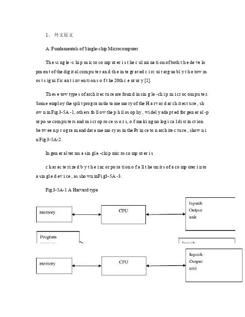
1、外文原文A: Fundamentals of Single-chip MicrocomputerTh e si ng le -c hi p m ic ro co mp ut er i s t he c ul mi na ti on of both t h e de ve lo pm en t of the dig it al com pu te r an d th e in te gr at ed c i rc ui t arg ua bl y t h e tow m os t s ig ni f ic an t i nv en ti on s o f t he 20th c e nt ur y [1].Th es e tow type s of arch it ec tu re are foun d in sin g le -ch i p m i cr oc om pu te r. Som e empl oy the spli t prog ra m/da ta me mo ry of the H a rv ar d ar ch it ect u re , sh ow n in Fig.3-5A -1, oth ers fo ll ow the p h il os op hy , wi del y ada pt ed for gen er al -p ur po se com pu te rs and m i cr op ro ce ss o r s, o f ma ki ng no log i ca l di st in ct ion be tw ee n p r og ra m and dat a me mo ry as in the Pr in ce to n arch ite c tu re , show n i n Fig.3-5A-2.In gen er al ter ms a sin gl e -chi p mic ro co mp ut er i sc h ar ac te ri zed b y t he i nc or po ra ti on of a ll t he un it s of a co mp uter i n to a sin gl e d ev i ce , as sho wn inFi g3-5A -3.Fig.3-5A-1 A Harvard typeFig.3-5A-2. A conventional Princeton computerFig3-5A-3. Principal features of a microcomputerRead only memory (ROM.R OM is usua ll y for the pe rm an ent,n o n-vo la ti le stor a ge of an app lic a ti on s pr og ra m .M an ym i cr oc om pu te rs and m are inte nd e d for high -v ol um e ap pl ic at ions a n d he nc e t h e eco n om ic al man uf act u re of th e de vic e s re qu ir es t h at t he cont en t s o f t he prog ra m me m or y be co mm it t ed perm a ne ntly d u ri ng the man ufa c tu re of ch ip s .Cl ea rl y, thi s im pl ie s a r i go ro us app ro ach to ROM cod e deve l op me nt sin ce cha ng es can not b e mad e afte r manu f a c tu re .Th is dev e lo pm en t proc ess may invo lv e e m ul at io n us in g aso ph is ti ca te d de ve lo pm en t sy ste m wit h a h a rd wa re emu la tio n cap ab il it y as w el l as the use o f po we rf ul s o ft wa re too ls.So me man uf act u re rs pro vi de add it io na l RO M opt i on s by i n cl ud in g in their ra n ge dev ic es wit h (or int en de d fo r use wit h u s er pro gr am ma ble me mo ry. Th e sim p le st of th es e is usu al ly d e vi ce whi ch can op er at e in a micro p ro ce ssor mod e by usi ng som e o f the inp ut /outp u t li ne s as an ad dr es s an d da ta b us fora c ce ss in g ex te rna l mem or y. Thi s t y pe of de vi ce can beh av ef u nc ti on al ly as th e sing le chip mi cr oc om pu te r from whi ch it is d e ri ve d al be it wit h re st ri ct ed I/O and a mod if ied ex te rn al c i rc ui t. The use of thes e d ev ic es is com mo n eve n in prod uc ti on c i rc ui ts wher e t he vo lu me does no tj us ti f y t h e d ev el o pm en t c osts o f c us to m o n -ch i p R OM [2];t he re c a n s ti ll bea s ignif i ca nt saving i n I /O and o th er c h ip s com pa re d to a conv en ti on al mi c ro pr oc es sor b a se d ci rc ui t. Mor e ex ac t re pl ace m en t fo r RO M dev i ce s ca n be o b ta in ed in th e fo rm of va ri an ts w it h 'p ig gy -b ack 'E P RO M(Er as ab le pro gr am ma bl e ROM s oc ke ts or dev ic e s with EPROM i n st ea d o f RO M 。
关于plc的外文文献翻译中英文翻译外文翻译

外文资料译文PLC technique discussion and future developmentAlong with the development of the ages, the technique that is nowadays is also gradually perfect, the competition plays more strong; the operation that list depends the artificial has already can't satisfied with the current manufacturing industry foreground, also can't guarantee the request of the higher quantity and high new the image of the technique business enterprise.The people see in produce practice, automate brought the tremendous convenience and the product quantities for people up of assurance, also eased the personnel's labor strength, reduce the establishment on the personnel. The target control of the hard realization in many complicated production lines, whole and excellent turn, the best decision etc., well-trained operation work, technical personnel or expert, governor but can judge and operate easily, can acquire the satisfied result. The research target of the artificial intelligence makes use of the calculator exactly to carry out, imitate these intelligences behavior, moderating the work through person's brain and calculators, with the mode that person's machine combine, for resolve the very complicated problem to look for the best pathPLC language is not we imagine of edit collected materials the language or language of Cs to carry on weaving the distance, but the trapezoid diagram that the adoption is original after the electric appliances to control, make the electrical engineering teacher while weaving to write the procedure very easy comprehended the PLC language, and a lot of non- electricity professional also very quickly know and go deep into to the PLC.Is PLC one of the advantage above and only, this is also one part that the people comprehend more and easily, in a lot of equipments, the people havealready no longer hoped to see too many control buttons, they damage not only and easily and produce the artificial error easiest, small is not a main error perhaps you can still accept; But lead even is a fatal error greatly is what we can't is tolerant of. New technique always for bringing more safe and convenient operation for us, make we a lot of problems for face on sweep but light, do you understand the HMI? Says the HMI here you basically not clear what it is, also have no interest understanding, change one inside text explains it into the touch to hold or man-machine interface you knew, and it combines with the PLC to our larger space.When we are work a work piece, giving the PLC a signal, counting PLC inner part the machine add 1 to compute us for a day of workload, a count the machine and can solve problem in brief, certainly they also can keep the data under the condition of dropping the electricity, urging the data not to throw to lose, this is also what we hope earnestly.The PLC still has the function that the high class counts the machine, being us while accept some dates of high speed, the high speed that here say is the data of the in all aspects tiny second class, for example the bar code scanner is scanning the data continuously, calculating high-speed signal of the data processor DSP etc., we will adopt the high class to count the machine to help we carry on count. It at the PLC carries out the procedure once discover that the high class counts the machine to should of interruption, will let go of the work on the hand immediately. The trapezoid diagram procedure that passes by to weave the distance again explains the high class for us to carry out procedure to count machine would automatic performance to should of work, thus rise the Class that the high class counts the machine to high one Class.You heard too many this phrases perhaps:" crash", the meaning that is mostly is a workload of CPU to lead greatly, the internal resources shortage etc. the circumstance can't result in procedure circulate. The PLC also has the similar circumstance, there is a watchdog WDT in the inner part of PLC, wecan establish time that a procedure of WDT circulate, being to appear the procedure to jump to turn the mistake in the procedure movement process or the procedure is busy, movement time of the procedure exceeds WDT constitution time, the CPU turn but the WDT reset the appearance. The procedure restarts the movement, but will not carry on the breakage to the interruption.The PLC development has already entered for network ages of correspondence from the mode of the one, and together other works control the net plank and I/ O card planks to carry on the share easily. A state software can pass all se hardwires link, more animation picture of keep the view to carries on the control, and cans pass the Internet to carry on the control in the foreign land, the blast-off that is like the absolute being boat is to adopt this kind of way to make airship go up the sky.The development of the higher layer needs our continuous effort to obtain. The PLC emergence has already affected a few persons fully, we also obtained more knowledge and precepts from the top one experience of the generation, coming to the continuous development PLC technique, push it toward higher wave tide.Knowing the available PLC network options and their best applications will ensure an efficient and flexible control system design.The programmable logic controller's (PLC's) ability to support a range of communication methods makes it an ideal control and data acquisition device for a wide variety of industrial automation and facility control applications. However, there is some confusion because so many possibilities exist. To help eliminate this confusion, let's list what communications are available and when they would be best applied.To understand the PLC's communications versatility, let's first define the terms used in describing the various systems.ASCII: This stands for "American Standard Code for Information Interchange." As shown in Fig. 1, when the letter "A" is transmitted, forinstance, it's automatically coded as "65" by the sending equipment. The receiving equipment translates the "65" back to the letter "A." Thus, different devices can communicate with each other as long as both use ASCII code.ASCII module: This intelligent PLC module is used for connecting PLCs to other devices also capable of communicating using ASCII code as a vehicle.Bus topology: This is a linear local area network (LAN) arrangement, as shown in Fig. 2A, in which individual nodes are tapped into a main communications cable at a single point and broadcast messages. These messages travel in both directions on the bus from the point of connection until they are dissipated by terminators at each end of the bus.CPU: This stands for "central processing unit," which actually is that part of a computer, PLC, or other intelligent device where arithmetic and logical operations are performed and instructions are decoded and executed.Daisy chain: This is a description of the connection of individual devices in a PLC network, where, as shown in Fig. 3, each device is connected to the next and communications signals pass from one unit to the next in a sequential fashion.Distributed control: This is an automation concept in which portions of an automated system are controlled by separate controllers, which are located in close proximity to their area of direct control (control is decentralized and spread out over the system).Host computer: This is a computer that's used to transfer data to, or receive data from, a PLC in a PLC/computer network.Intelligent device: This term describes any device equipped with its own CPU.I/O: This stands for "inputs and outputs," which are modules that handle data to the PLC (inputs) or signals from the PLC (outputs) to an external device.Kbps: This stands for "thousand bits per second," which is a rate of measure for electronic data transfer.Mbps: This stands for "million bits per second."Node: This term is applied to any one of the positions or stations in a network. Each node incorporates a device that can communicate with all other devices on the network.Protocol: The definition of how data is arranged and coded for transmission on a network.Ring topology. This is a LAN arrangement, as shown in Fig. 2C, in which each node is connected to two other nodes, resulting in a continuous, closed, circular path or loop for messages to circulate, usually in one direction. Some ring topologies have a special "loop back" feature that allows them to continue functioning even if the main cable is severed.RS232. This is an IEEE standard for serial communications that describes specific wiring connections, voltage levels, and other operating parameters for electronic data communications. There also are several other RS standards defined.Serial: This is an electronic data transfer scheme in which information is transmitted one bit at a time.Serial port: This the communications access point on a device that is set up for serial communications.Star topology. This is a LAN arrangement in which, as shown in Fig. 2B, nodes are connected to one another through a central hub, which can be active or passive. An active hub performs network duties such as message routing and maintenance. A passive central hub simply passes the message along to all the nodes connected to it.Topology: This relates to a specific arrangement of nodes in a LAN in relation to one another.Transparent: This term describes automatic events or processes built into a system that require no special programming or prompting from an operator.Now that we're familiar with these terms, let's see how they are used in describing the available PLC network options.PLC network optionsPLC networks provide you with a variety of networking options to meet specific control and communications requirements. Typical options include remote I/O, peer-to-peer, and host computer communications, as well as LANs. These networks can provide reliable and cost-effective communications between as few as two or as many as several hundred PLCs, computers, and other intelligent devices.Many PLC vendors offer proprietary networking systems that are unique and will not communicate with another make of PLC. This is because of the different communications protocols, command sequences, error-checking schemes, and communications media used by each manufacturer.However, it is possible to make different PLCs "talk" to one another; what's required is an ASCII interface for the connection(s), along with considerable work with software.Remote I/0 systemsA remote I/O configuration, as shown in Fig. 4A, has the actual inputs and outputs at some distance from the controller and CPU. This type of system, which can be described as a "master-and-slave" configuration, allows many distant digital and analog points to be controlled by a single PLC. Typically, remote I/Os are connected to the CPU via twisted pair or fiber optic cables.Remote I/O configurations can be extremely cost-effective control solutions where only a few I/O points are needed in widely separated areas. In this situation, it's not always necessary, or practical for that matter, to have a controller at each site. Nor is it practical to individually hard wire each I/O point over long distances back to the CPU. For example, remote I/O systems can be used in acquiring data from remote plant or facility locations. Information such as cycle times, counts, duration or events, etc. then can be sent back to the PLC for maintenance and management reporting.In a remote I/O configuration, the master controller polls the slaved I/O for its current I/O status. The remote I/O system responds, and the master PLCthen signals the remote I/O to change the state of outputs as dictated by the control program in the PLC's memory. This entire cycle occurs hundreds of times per second.Peer-to-peer networksPeer-to-peer networks, as shown in Fig. 4B, enhance reliability by decentralizing the control functions without sacrificing coordinated control. In this type of network, numerous PLCs are connected to one another in a daisy-chain fashion, and a common memory table is duplicated in the memory of each. In this way, when any PLC writes data to this memory area, the information is automatically transferred to all other PLCs in the network. They then can use this information in their own operating programs.With peer-to-peer networks, each PLC in the network is responsible for its own control site and only needs to be programmed for its own area of responsibility. This aspect of the network significantly reduces programming and debugging complexity; because all communications occur transparently to the user, communications programming is reduced to simple read-and-write statements.In a peer-to-peer system, there's no master PLC. However, it's possible to designate one of the PLCs as a master for use as a type of group controller. This PLC then can be used to accept input information from an operator input terminal, for example, sending all the necessary parameters to other PLCs and coordinating the sequencing of various events.Host computer linksPLCs also can be connected with computers or other intelligent devices. In fact, most PLCs, from the small to the very large, can be directly connected to a computer or part of a multi drop host computer network via RS232C or RS422 ports. This combination of computer and controller maximizes the capabilities of the PLC, for control and data acquisition, as well as the computer, for data processing, documentation, and operator interface.In a PLC/computer network, as shown in Fig. 4C, all communications areinitiated by the host computer, which is connected to all the PLCs in a daisy-chain fashion. This computer individually addresses each of its networked PLCs and asks for specific information. The addressed PLC then sends this information to the computer for storage and further analysis. This cycle occurs hundreds of times per second.Host computers also can aid in programming PLCs; powerful programming and documentation software is available for program development. Programs then can be written on the computer in relay ladder logic and downloaded into the PLC. In this way, you can create, modify, debug, and monitor PLC programs via a computer terminal.In addition to host computers, PLCs often must interface with other devices, such as operator interface terminals for large security and building management systems. Although many intelligent devices can communicate directly with PLCs via conventional RS232C ports and serial ASCII code, some don't have the software ability to interface with individual PLC models. Instead, they typically send and receive data in fixed formats. It's the PLC programmer's responsibility to provide the necessary software interface.The easiest way to provide such an interface to fixed-format intelligent devices is to use an ASCII/BASIC module on the PLC. This module is essentially a small computer that plugs into the bus of the PLC. Equipped with RS232 ports and programmed in BASIC, the module easily can handle ASCII communications with peripheral devices, data acquisition functions, programming sequences, "number crunching," report and display generation, and other requirements.Access, protocol, and modulation functions of LANsBy using standard interfaces and protocols, LANs allow a mix of devices (PLCs, PCs, mainframe computers, operator interface terminals, etc.) from many different vendors to communicate with others on the network.Access: A LAN's access method prevents the occurrence of more than one message on the network at a time. There are two common access methods.Collision detection is where the nodes "listen" to the network and transmit only if there are no other messages on the network. If two nodes transmit simultaneously, the collision is detected and both nodes retransmit until their messages get through properly.Token passing allows each node to transmit only if it's in possession of a special electronic message called a token. The token is passed from node to node, allowing each an opportunity to transmit without interference. Tokens usually have a time limit to prevent a single node from tying up the token for a long period of time.Protocol: Network protocols define the way messages are arranged and coded for transmission on the LAN. The following are two common types.Proprietary protocols are unique message arrangements and coding developed by a specific vendor for use with that vendor's product only.Open protocols are based on industry standards such as TCP/IP or ISO/OSI models and are openly published.Modulation: Network modulation refers to the way messages are encoded for transmission over a cable. The two most common types are broadband and baseband.Network transmission interfacesThe vast majority of PLC communications is done via RS232C and twisted pair cables. Most PLCs have an RS232 port and are capable of handling communications with host computers, printers, terminals, and other devices. Maximum transmission speed is Kbps.The distance and data transmission rates are standards for the various interfaces. Their actual performance is a function of the driving devices and varies significantly between manufacturers. As such, you should consult the manufacturer's specifications for actual distance and data transmission rate capabilities.The only real limitation on RS232C is the 50-ft recommended distance between devices. While RS232C installations often can achieve cablingdistances greater than this, the "unbalanced" design of the interface results in a greater susceptibility to surrounding electrical noise and reduced data integrity. This is particularly true where electromagnetic interference (EMI) and radio-frequency interference (RFI) are known to exist.When longer transmission distances are needed, RS422 is a better choice. Unlike the RS232C interface, RS422 is "balanced." Each of its primary signals consists of two wires that are always at opposite logic levels, with respect to signal ground. As a result, the interface can achieve longer transmission distance (4000 ft) and higher data transmission rates (up to 90 Kbps). In shorter runs (less than 50 ft), data transfer can reach 10 Mbps.Fiber optic communications are gaining greater acceptance and are being used in more and more installations. Fiber optic cable is virtually impervious to harsh environmental conditions and electrical noise. Also, these links can span extremely long distances and transmit data at very high speeds. For example, in some LAN systems, these links can transmit at relatively high speeds and span long distances before requiring a repeater. When repeaters are used, virtually unlimited distances can be achieved.可编程操纵器技术讨论与以后进展随着时期的进展,现今的技术也日趋完善、竞争愈演愈烈;单靠人工的操作已不能知足于目前的制造业前景,也无法保证更高质量的要求和高新技术企业的形象.人们在生产实践中看到,自动化给人们带来了极大的便利和产品质量上的保证,同时也减轻了人员的劳动强度,减少了人员上的编制.在许多复杂的生产进程中难以实现的目标操纵、整体优化、最正确决策等,熟练的操作工、技术人员或专家、治理者却能够容易判定和操作,能够取得中意的成效.人工智能的研究目标正是利用运算机来实现、模拟这些智能行为,通过人脑与运算机和谐工作,以人机结合的模式,为解决十分复杂的问题寻觅最正确的途径PLC的语言并非是咱们所想象的汇编语言或C语言来进行编程,而是采纳原有的继电器操纵的梯形图,使得电气工程师在编写程序时很容易就明白得了PLC的语言,而且很多的非电气专业人士也对PLC专门快熟悉并深切。
(自动化专业)毕业论文文献翻译中英文对照
(自动化专业)毕业论文文献翻译中英文对照毕业设计外文资料翻译题目可编程控制器技术讨论与未来发展专业电气工程及其自动化PLC technique discussion and future developmentK. Begain, M. ErmelChair for Telecommunications, Dresden University of Technology,01062 Dresden, GermanyAbstract: Programmable Logic Controllers (PLC), a computing device invented by Richard E.Morley in 1968, have been widely used in industry including manufacturing systems, transportation systems, chemical process facilities, and many others. At that time, the PLC placed the hardwired logic with soft-wired logic or so-called relay ladder logic(RLL), a programming language visually resembling the hardwired logic, and reduced thereby the configuration time from 6 months down to 6 days [Moody and Morley,1999].Although PC based control has started to come into place, PLC based control will remain the technique to which the majority of industrial applications will adhere due to its higher performance, lower price, and superior reliability in harsh environments. Moreover, according to a study on the PLC market of Frost and Sullivan [1995], an increase of the annual sales volume to 15 million PLCs per year with the hardware value of more than 8 billion US dollars has been predicted, though the prices of computing hardware is steadily dropping. The inventor of the PLC, Richard E Morley, fairly considers the PLC market as a 5-billion industry at the present time.Key Words:PLC ,performance ,market1 IntroductionAlong with the development of the ages, the technique that is nowadays is also gradually perfect, the competition plays more more strong; the operation that list depends the artificial has already can't satisfied with the current manufacturing industry foreground, also can't guarantee the request of the higher quantity and high new the image of the technique business enterprise.The people see in produce practice, automate brought the tremendous convenience and the product quantities for people up of assurance, also eased the personnel's labor strength, reduce the establishment on the personnel. The target control of the hard realization in many complicated production lines, whole and excellent turn, the best decision etc., well-trained operation work, technical personnel or expert, governor but can judge and operate easily, can acquire the satisfied result. The research target of the artificial intelligence makes use of the calculator exactly to carry out, imitate these intelligences behavior, moderating the work through person's brain and calculators, with the mode that person's machine combine, for resolve the very complicated problem to look for the best pathWe come in sight of the control that links after the electric appliances in various situation, that is already the that time generation past, now of after use in the mold a perhaps simple equipments of grass-roots control that the electric appliances can do for the low level only;And the PLC emergence also became the epoch-making topic, adding the vivid software control through a very and stable hardware, making the automation head for the new high tide.2 PLC characteristics and containment2.1 The PLC biggest characteristicsThe PLC biggest characteristics lie in: The electrical engineering teacher already no longer electric hardware up too many calculationses of cost, as long as order the importation that the button switch or the importation of the sensors order to link the PLC up can solve problem, pass to output to order the conjunction contact machine or control the start equipments of the big power after the electric appliances, but the exportation equipments direct conjunction of the small power can.Figure 1. Open frame PLC2.2 PLC internal containmentPLC internal containment have CPU, and take to have an I/ O for expand of exterior to connect a people's address and saving machine three big pieces to constitute, CPU core is from an or many is tired to add the machine to constitute, mathematics that they have the logic operation ability, and can read the procedure save the contents of the machine to drive the homologous saving machine and I/ Os to connect after pass the calculation; The I/ O add inner part is tired the input and output system of the machine and exterior link, and deposit the related data into the procedure saving machine or data saving machine; The saving machine can deposit the data that the I/ O input in the saving machine, and in work adjusting to become tired to add the machine and I/ Os to connect, saving machine separately saving machine RAM of the procedure saving machine ROM and datas, the ROM can can do deposit of the data permanence in the saving machine, but RAM only for the CPU computes the temporary calculation usage of hour of buffer space.Figure 2. PLC input and output circuits2.3 PLC advantageThe PLC anti- interference is very and excellent, our root need not concern its service life and the work situation bad, these all problems have already no longer become the topic that we fail, but stay to our is a concern to come to internal resources of make use of the PLC to strengthen the control ability of the equipments for us, make our equipments more gentle.PLC language is not we imagine of edit collected materials the language or language of Cs to carry on weaving the distance, but the trapezoid diagram that the adoption is original after the electric appliances to control, make the electrical engineering teacher while weaving to write the procedure very easy comprehended the PLC language, and a lot of non- electricity professional also very quickly know and go deep into to the PLC.3 HMIIs PLC one of the advantage above and only, this is also one part that the people comprehend more and easily, in a lot of equipmentses, the people have already no longer hoped to see too many control buttons, they damage not only and easily and produce the artificial error easiest, small is not a main error perhaps you can still accept; But lead even is a fatal error greatly is what we can't is tolerant of. New technique always for bringing more safe and convenient operation for us, make we a lot of problems for face on sweep but light, do you understand the HMI? Says the HMI here you basically not clear what it is, also have no interest understanding, change one inside text explains it into the touch to hold or man-machine interface you knew, it combines with the PLC to our larger space.HMI the control not only only is reduced the control press button, increase the vivid of the control, more main of it is can sequence of, and at can the change data input to output the feedback with data, control in the temperature curve of imitate but also can keep the manifestation of view to come out. And can write the function help procedure through a plait to provide the help of various what lies in one's power, the one who make operate reduces the otiose error. Currently the HMI factory is also more and more, the function is also more and more strong, the price is also more and more low, the noodles of the usage are wide more and more. The HMI foreground can say that think ° to be good very.4 PLC correspondence and data transmissionAt a lot of situations, the list is is a smooth movement that can't guarantee theequipments by the control of the single machine, but pass the information exchanges of the equipments and equipments to attain the result that we want. For example fore pack and the examination of the empress work preface, we will arrive wrapping information feedback to examine the place, and examine the information of the place to also want the feedback to packing. Pass the information share thus to make both the chain connect, becoming a total body, the match of your that thus make is more close, at each other attain to reflect the result that mutually flick.The PLC correspondence has already come more more body now its value, at the PLC and correspondence between PLCs, can pass the communication of the information and the share of the datas to guarantee that of the equipments moderates mutually, the result that arrive already to repair with each other. Data conversion the adoption RS232 between PLC connect to come to the transmission data, but the RS232 pick up a people and can guarantee 10 meters only of deliver the distance, if in the distance of 1000 meters we can pass the RS485 to carry on the correspondence, the longer distance can pass the MODEL only to carry on deliver.The PLC data transmission is just to be called a form to it in a piece of and continuous address that the data of the inner part delivers the other party, we, the PLC of the other party passes to read data in the watch to carry on the operation. If the data that data in the watch is a to establish generally, that is just the general data transmission, for example today of oil price rise, I want to deliver the price of the oil price to lose the oil ally on board, that is the share of the data; But take data in the watch for an instruction procedure that controls the PLC, that had the difficulty very much, for example you have to control one pedestal robot to press the action work that you imagine, you will draw up for it the form that a procedure combine with the data sends out to pass by.Figure 3. PLC connection with experiments board.4.1 Form of information transmission4.1.1 Simplex and DuplexThe form that information transport contain Simplex, the Half duplex and the Full duplex.The meaning of the Simplex also is to say both, a can send out only, but a can receive only, for example a spy he can receive the designation of the superior only, but can't give the superior reply; Half duplex is also 2 and can can send out similar to accept the data, but can't send out and accept at the same time, for example when you make a phone call is to can't answer the phone, the other party also; But the Half duplex is both can send out and accept the data, and can send out and accept at the same time. Be like the Internet is a typical example.4.1.2 Synchronous and AsynchronousThe process that information transport also has synchronous and asynchronous: The data line and the clock lines are synchronous when synchronous meaning lie in sending out the data, is also the data signal and the clock signals to be carry on by the CPU to send out at the same time, this needs to all want the specialized clock signal each other to carry on the transmission and connect to send, and is constrained, the characteristics of this kind of method lies in its speed very quick, but correspond work time of take up the CPU and also want to be long oppositely, at the same time the technique difficulty also very big. Itsrequest lies in can'ting have an error margins in a datas deliver, otherwise the whole pieceaccording to compare the occurrence mistake, this on the hardware is a bigger difficulty. Applied more and more extensive in some appropriative equipmentses, be like the appropriative medical treatment equipments, the numerical signal equipments...etc., in compare the one data deliver, its result is very good.And asynchronous is an application the most extensive, this receive benefit in it of technique difficulty is opposite and want to be small, at the same time not need to prepare the specialized clock signal, its characteristics to lie in, its data is partition, the long-lost send out and accept, be the CPU is too busy of time can grind to a stop sex to work, also reduced the difficulty on the hardware, the data throw to lose at the same time opposite want to be little, we can pass the examination of the data to observe whether the data that we send out has the mistake or not, be like strange accidentally the method, tired addition and eight efficacies method etc., can use to helps whether the data that we examine to send out have or not the mistake occurrence, pass the feedback to carry on the discriminator.4.1.3 Parallel and SerialA line of transmission of the information contain a string of and combine the cent of: The usual PLC is 8 machines, certainly also having 16 machines. We can be an at the time of sending out the data a send out to the other party, also can be 88 send out the data to the other party, an and 8 differentiationses are also the as that we say to send out the data and combine sends out the data. A speed is more and slowly, but as long as 2 or three lines can solve problem, and can use the telephone line to carry on the long range control. But combine the oscular transmission speed is very quick of, it is a string of oscular of 25600%, occupy the advantage in the short distance, the in view of the fact TTL electricity is even, being limited by the scope of one meter generally, it combine unwell used for the data transmission of the long pull, thus the cost is too expensive.Under a lot of circumstances we are total to like to adopt the string to combine the conversion chip to carry on deliver, under this kind of circumstance not need us to carry on to depositted the machine to establish too and complicatedly, but carry on the data exchanges through the data transmission instruction directly, but is not a very viable way in the correspondence, because the PLC of the other party must has been wait for your data exportation at the time of sending out the data, it can't do other works.4.2 InterruptWhen you are reading the book, you hear someone knock on door, you stop to start up of affair, open the door and combine to continue with the one who knock on door a dialogue, the telephone of this time rang, you signal hint to connect a telephone, afterconnecting the telephone through, return overdo come together knock on door to have a conversation, after dialogue complete, you continue again to see your book, this kind of circumstance we are called the interruption to it, it has the authority, also having sex of have the initiative, the PLC had such function .Its characteristics lie in us and may meet the urgently abrupt affairs in the operation process of the equipments, we want to stop to start immediately up of work, the whereabouts manages the more important affair, this kind of circumstance is we usually meet of, PLC while carry out urgent mission, total will keep the current appearance first, for example the address of the procedure, CPU of tired add the machine data etc., be like to to stick down which the book that we see is when we open the door the page or simply make a mark, because we treat and would still need to continue immediately after book of see the behind. The CPU always does the affair that should do according to our will, but your mistake of give it an affair, it also would be same to do, this we must notice.The interruption is not only a, sometimes existing jointly with the hour several inside break, break off to have the preferred Class, they will carry out the interruption of the higher Class according to person's request. This kind of breaks off the medium interruption to also became to break off the set. The Class that certainly break off is relevant according to various resources of CPU with internal PLC, also following a heap of capacity size of also relevant fasten.The contents that break off has a lot of kinds, for example the exterior break off, correspondence in of send out and accept the interruption and settle and the clock that count break off, still have the WDT to reset the interruption etc., they enriched the CPU to respond to the category while handle various business. Speak thus perhaps you can't comprehend the internal structure and operation orders of the interruption completely also, we do a very small example to explain.4.3 Emergency stop buttonEach equipments always will not forget a button, it also is at we meet the urgent circumstance use of, that is nasty to stop the button. When we meet the Human body trouble and surprised circumstances we as long as press it, the machine stops all operations immediately, and wait for processing the over surprised empress recover the operation again.Nasty stop the internal I/ O of the internal CPU of the button conjunction PLC to connect up, be to press button an exterior to trigger signal for CPU, the CPU carries on to the I/ O to examine again, being to confirm to have the exterior to trigger the signal, CPU protection the spot breaks off procedure counts the machine turn the homologous exteriorI/ O automatically in the procedure to go to also, be exterior interruption procedure processing complete, the procedure counts the machine to return the main procedure to continue to work.Have 1:00 can what to explain is we generally would nasty stop the button of exterior break off to rise to the tallest Class, thus guarantee the safety.4.4 PLC Counting functionWhen we are work a work piece, giving the PLC a signal, counting PLC inner part the machine add 1 to compute us for a day of workload, a count the machine and can solve problem in brief, certainly they also can keep the data under the condition of dropping the electricity, urging the data not to throw to lose, this is also what we hope earnestly.The PLC still has the function that the high class counts the machine, being us while accept some datas of high speed, the high speed that here say is the data of the in all aspects tiny second class, for example the bar code scanner is scanning the data continuously, calculating high-speed signal of the data processor DSP etc., we will adopt the high class to count the machine to help we carry on count. It at the PLC carries out the procedure once discover that the high class counts the machine to should of interruption, will let go of the work on the hand immediately. The trapezoid diagram procedure that passes by to weave the distance again explains the high class for us to carry out procedure to count machine would automatic performance to should of work, thus rise the Class that the high class counts the machine to high one Class.You heard too many this phrases perhaps:" crash", the meaning that is mostly is a workload of CPU to lead greatly, the internal resources shortage etc. the circumstance can't result in procedure circulate. The PLC also has the similar circumstance, there is a watchdog WDT in the inner part of PLC, we can establish time that a procedure of WDT circulate, being to appear the procedure to jump to turn the mistake in the procedure movement process or the procedure is busy, movement time of the procedure exceeds WDT constitution time, the CPU turn but the WDT reset the appearance. The procedure restarts the movement, but will not carry on the breakage to the interruption.Figure 4. Overall board design.5 PLC development in the futureThe PLC development has already entered for network ages of correspondence from the mode of the one, and together other works control the net plank and I/ O card planks to carry on the share easily. A state software can pass all se hardwares link, more animation picture of keep the view to carries on the control, and cans pass the Internet to carry on the control in the foreign land, the blast-off that is like the absolute being boat No.5 is to adopt this kind of way to make airship go up the sky.The development of the higher layer needs our continuous effort to obtain.The PLC emergence has already affected a few persons fully, we also obtained more knowledge and precepts from the top one experience of the generation, coming to the continuous development PLC technique, push it toward higher wave tide.References[1] R. Alur, C. Courcoubetis, and D. Dill. Model-Checking for Real-Time Systems.In Fifth Annual IEEE Symp. on Logic in Computer Science, pages 414{425.IEEE Press, 1990. [2] R. Alur and D.L. Dill. A theory of timed automata. Theoret. Comput. Sci.,126:183{235, 1994.[3] R. Alur, T. Henzinger, and E. Sontag, editors. Hybrid Systems III, volume 1066 of Lecture Notes in Computer Science. Springer-Verlag, 1996.[4] J. Bengtsson, K.G. Larsen, F. Larsson, P. Pettersson, and Wang Yi. Uppaal {a ToolSuite for Automatic Verification of Real-Time Systems. In Alur et al.[3]. 232{243.[5] D. Bosscher, I. Polak, and F. Vaandrager. Verification of an Audio Control Protocol. InH. Langmaack, W.-P. de Roever, and J. Vytopil, editors, Formal Techniques in Real-Time and Fault-Tolerant Systems, volume 863 of Lecture Notes in Computer Science, pages 170{192. Springer-Verlag, 1994.PLC technique discussion and future development, 2010, 130(9): 2436-2443.可编程控制器技术讨论与未来发展K.培根, M. 厄米尔通信教授, 德累斯顿科技大学,01062德累斯顿,德国摘要可编程逻辑控制器(PLC)是Richard E.Morley在1968年发明的一种具备运算功能的设备,现已被广泛的应用到工业中,包括制造系统、交通系统、化工过程设备等。
3-电气工程及其自动化专业 外文文献 英文文献 外文翻译 plc方面
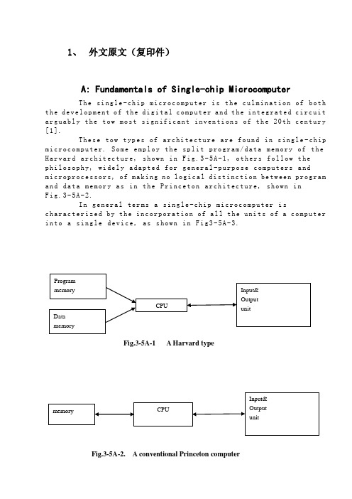
1、外文原文(复印件)A: Fundamentals of Single-chip MicrocomputerTh e si ng le-ch i p mi cr oc om pu ter is t he c ul mi nat i on o f bo th t h e d ev el op me nt o f th e d ig it al com p ut er an d t he int e gr at ed ci rc ui ta r gu ab ly th e t ow m os t s i gn if ic ant i nv en ti on s o f t h e 20t h c en tu ry[1].Th es e to w typ e s of a rc hi te ctu r e ar e fo un d i n s in gl e-ch ip m i cr oc om pu te r. So m e em pl oy t he sp l it p ro gr am/d ata me mo ry o f th e H a rv ar d ar ch it ect u re, sh ow n in Fi g.3-5A-1, o th ers fo ll ow t hep h il os op hy, wi del y a da pt ed f or ge n er al-p ur po se co m pu te rs a ndm i cr op ro ce ss or s, of ma ki ng no lo gi c al di st in ct io n be tw ee n p ro gr am a n d da ta m em or y a s i n th e Pr in cet o n ar ch it ec tu re,sh ow n inF i g.3-5A-2.In g en er al te r ms a s in gl e-chi p m ic ro co mp ut er i sc h ar ac te ri zed b y the i nc or po ra tio n of al l t he uni t s o f a co mp ut er i n to a s in gl e dev i ce, as s ho wn in Fi g3-5A-3.Fig.3-5A-1 A Harvard typeFig.3-5A-2. A conventional Princeton computerFig3-5A-3. Principal features of a microcomputerRead only memory (ROM).R OM i s u su al ly f or th e p er ma ne nt,n o n-vo la ti le s tor a ge o f an a pp lic a ti on s pr og ra m .M an ym i cr oc om pu te rs an d mi cr oc on tr ol le r s a re in t en de d fo r h ig h-v ol ume a p pl ic at io ns a nd h en ce t he e co nom i ca l ma nu fa ct ure of t he d ev ic es r e qu ir es t ha t the co nt en ts o f the pr og ra m me mo ry b e co mm it te dp e rm an en tl y d ur in g th e m an uf ac tu re o f c hi ps . Cl ear l y, th is im pl ie sa ri g or ou s a pp roa c h t o R OM co de d e ve lo pm en t s in ce c ha ng es ca nn otb e m ad e af te r man u fa ct ur e .T hi s d e ve lo pm en t pr oce s s ma y in vo lv e e m ul at io n us in g a s op hi st ic at ed deve lo pm en t sy st em w i th a ha rd wa re e m ul at io n ca pa bil i ty a s we ll a s th e u se of po we rf ul so ft wa re t oo ls.So me m an uf act u re rs p ro vi de ad d it io na l RO M opt i on s byi n cl ud in g i n th ei r ra ng e de vi ce s wi th (or i nt en de d fo r us e wi th) u s er pr og ra mm ab le m em or y. Th e s im p le st of th es e i s us ua ll y d ev ice w h ic h ca n op er ate in a m ic ro pr oce s so r mo de b y usi n g so me o f th e i n pu t/ou tp ut li ne s as a n ad dr es s an d da ta b us f or acc e ss in g e x t er na l m e mo ry. T hi s t ype o f d ev ic e c an b e ha ve fu nc ti on al l y a s t he si ng le c h ip mi cr oc om pu te r fr om wh ic h i t i s de ri ve d a lb eit w it h r es tr ic ted I/O an d a mo di fie d e xt er na l ci rcu i t. T he u se o f t h es e RO Ml es sd e vi ce s is c om mo n e ve n in p ro du ct io n c ir cu it s wh er e t h e v ol um e do es n o t ju st if y th e d e ve lo pm en t co sts of c us to m on-ch i p RO M[2];t he re c a n st il l b e a si g ni fi ca nt s a vi ng in I/O a nd ot he r c hi ps co mp ar ed t o a c on ve nt io nal mi cr op ro ce ss or b as ed c ir cu it. M o re e xa ctr e pl ac em en t fo r RO M d ev ic es c an b e o bt ai ne d in t he f o rm o f va ri an ts w i th 'pi gg y-ba ck'EP RO M(Er as ab le p ro gr am ma bl e ROM)s oc ke ts o rd e vi ce s w it h EP ROM i ns te ad o f R OM 。
电气工程与自动化毕业论文中英文资料外文翻译
电气工程与自动化毕业论文中英文资料外文翻译The Transformer on load ﹠Introduction to DC MachinesIt has been shown that a primary input voltage 1V can be transformed to any desired open-circuit secondary voltage 2E by a suitable choice of turns ratio. 2E is available for circulating a load current impedance. For the moment, a lagging power factor will be considered. The secondary current and the resulting ampere-turns 22N I will change the flux, tending to demagnetize the core, reduce m Φ and with it 1E . Because the primary leakage impedance drop is so low, a small alteration to 1Ewill cause an appreciable increase of primary current from 0I to a new value of 1Iequal to ()()i jX R E V ++111/. The extra primary current and ampere-turns nearly cancel the whole of the secondary ampere-turns. This being so , the mutual flux suffers only a slight modification and requires practically the same net ampere-turns 10N I as on no load. The total primary ampere-turns are increased by an amount 22N I necessary to neutralize the same amount of secondary ampere-turns. In thevector equation , 102211N I N I N I =+; alternatively, 221011N I N I N I -=. At full load,the current 0I is only about 5% of the full-load current and so 1I is nearly equalto 122/N N I . Because in mind that 2121/N N E E =, the input kV A which is approximately 11I E is also approximately equal to the output kV A, 22I E .The physical current has increased, and with in the primary leakage flux towhich it is proportional. The total flux linking the primary ,111Φ=Φ+Φ=Φm p , isshown unchanged because the total back e.m.f.,(dt d N E /111Φ-)is still equal and opposite to 1V . However, there has been a redistribution of flux and the mutual component has fallen due to the increase of 1Φ with 1I . Although the change is small, the secondary demand could not be met without a mutual flux and e.m.f.alteration to permit primary current to change. The net flux s Φlinking thesecondary winding has been further reduced by the establishment of secondaryleakage flux due to 2I , and this opposes m Φ. Although m Φ and 2Φ are indicatedseparately , they combine to one resultant in the core which will be downwards at theinstant shown. Thus the secondary terminal voltage is reduced to dt d N V S /22Φ-=which can be considered in two components, i.e. dt d N dt d N V m //2222Φ-Φ-=orvectorially 2222I jX E V -=. As for the primary, 2Φ is responsible for a substantiallyconstant secondary leakage inductance222222/Λ=ΦN i N . It will be noticed that the primary leakage flux is responsible for part of the change in the secondary terminal voltage due to its effects on the mutual flux. The two leakage fluxes are closely related; 2Φ, for example, by its demagnetizing action on m Φ has caused the changes on the primary side which led to the establishment of primary leakage flux.If a low enough leading power factor is considered, the total secondary flux and the mutual flux are increased causing the secondary terminal voltage to rise with load. p Φ is unchanged in magnitude from the no load condition since, neglecting resistance, it still has to provide a total back e.m.f. equal to 1V . It is virtually the same as 11Φ, though now produced by the combined effect of primary and secondary ampere-turns. The mutual flux must still change with load to give a change of 1E and permit more primary current to flow. 1E has increased this time but due to the vector combination with 1V there is still an increase of primary current.Two more points should be made about the figures. Firstly, a unity turns ratio has been assumed for convenience so that '21E E =. Secondly, the physical picture is drawn for a different instant of time from the vector diagrams which show 0=Φm , if the horizontal axis is taken as usual, to be the zero time reference. There are instants in the cycle when primary leakage flux is zero, when the secondary leakage flux is zero, and when primary and secondary leakage flux is zero, and when primary and secondary leakage fluxes are in the same sense.The equivalent circuit already derived for the transformer with the secondary terminals open, can easily be extended to cover the loaded secondary by the addition of the secondary resistance and leakage reactance.Practically all transformers have a turns ratio different from unity although such an arrangement is sometimes employed for the purposes of electrically isolating one circuit from another operating at the same voltage. To explain the case where 21N N ≠ the reaction of the secondary will be viewed from the primary winding. The reaction is experienced only in terms of the magnetizing force due to the secondary ampere-turns. There is no way of detecting from the primary side whether 2I is large and 2N small or vice versa, it is the product of current and turns which causesthe reaction. Consequently, a secondary winding can be replaced by any number of different equivalent windings and load circuits which will give rise to an identical reaction on the primary .It is clearly convenient to change the secondary winding to an equivalent winding having the same number of turns 1N as the primary.With 2N changes to 1N , since the e.m.f.s are proportional to turns, 2212)/('E N N E = which is the same as 1E .For current, since the reaction ampere turns must be unchanged 1222'''N I N I = must be equal to 22N I .i.e. 2122)/(I N N I =.For impedance , since any secondary voltage V becomes V N N )/(21, and secondary current I becomes I N N )/(12, then any secondary impedance, including load impedance, must becomeI V N N I V /)/('/'221=. Consequently,22212)/('R N N R = and 22212)/('X N N X = . If the primary turns are taken as reference turns, the process is called referring to the primary side.There are a few checks which can be made to see if the procedure outlined is valid.For example, the copper loss in the referred secondary winding must be the same as in the original secondary otherwise the primary would have to supply a differentloss power. ''222R I must be equal to 222R I . )222122122/()/(N N R N N I •• does infact reduce to 222R I .Similarly the stored magnetic energy in the leakage field)2/1(2LI which is proportional to 22'X I will be found to check as ''22X I . The referred secondary 2212221222)/()/(''I E N N I N N E I E kVA =•==.The argument is sound, though at first it may have seemed suspect. In fact, if the actual secondary winding was removed physically from the core and replaced by the equivalent winding and load circuit designed to give the parameters 1N ,'2R ,'2X and '2I , measurements from the primary terminals would be unable to detect any difference in secondary ampere-turns, kVA demand or copper loss, under normal power frequency operation.There is no point in choosing any basis other than equal turns on primary andreferred secondary, but it is sometimes convenient to refer the primary to the secondary winding. In this case, if all the subscript 1’s are interchanged for the subscript 2’s, the necessary referring constants are easily found; e.g. 2'1R R ≈,21'X X ≈; similarly 1'2R R ≈ and 12'X X ≈.The equivalent circuit for the general case where 21N N ≠ except that m r hasbeen added to allow for iron loss and an ideal lossless transformation has been included before the secondary terminals to return '2V to 2V .All calculations of internal voltage and power losses are made before this ideal transformation is applied. The behaviour of a transformer as detected at both sets of terminals is the same as the behaviour detected at the corresponding terminals of this circuit when the appropriate parameters are inserted. The slightly different representation showing the coils 1N and 2N side by side with a core in between is only used for convenience. On the transformer itself, the coils are , of course , wound round the same core.Very little error is introduced if the magnetising branch is transferred to the primary terminals, but a few anomalies will arise. For example ,the current shown flowing through the primary impedance is no longer the whole of the primary current.The error is quite small since 0I is usually such a small fraction of 1I . Slightlydifferent answers may be obtained to a particular problem depending on whether or not allowance is made for this error. With this simplified circuit, the primary and referred secondary impedances can be added to give:221211)/(Re N N R R += and 221211)/(N N X X Xe +=It should be pointed out that the equivalent circuit as derived here is only valid for normal operation at power frequencies; capacitance effects must be taken into account whenever the rate of change of voltage would give rise to appreciablecapacitance currents, dt CdV I c /=. They are important at high voltages and atfrequencies much beyond 100 cycles/sec. A further point is not the only possible equivalent circuit even for power frequencies .An alternative , treating the transformer as a three-or four-terminal network, gives rise to a representation which is just as accurate and has some advantages for the circuit engineer who treats all devices as circuit elements with certain transfer properties. The circuit on this basiswould have a turns ratio having a phase shift as well as a magnitude change, and the impedances would not be the same as those of the windings. The circuit would not explain the phenomena within the device like the effects of saturation, so for an understanding of internal behaviour .There are two ways of looking at the equivalent circuit:(a) viewed from the primary as a sink but the referred load impedance connected across '2V ,or(b) viewed from the secondary as a source of constant voltage 1V with internal drops due to 1Re and 1Xe . The magnetizing branch is sometimes omitted in this representation and so the circuit reduces to a generator producing a constant voltage 1E (actually equal to 1V ) and having an internal impedance jX R + (actually equal to 11Re jXe +).In either case, the parameters could be referred to the secondary winding and this may save calculation time .The resistances and reactances can be obtained from two simple light load tests. Introduction to DC MachinesDC machines are characterized by their versatility. By means of various combination of shunt, series, and separately excited field windings they can be designed to display a wide variety of volt-ampere or speed-torque characteristics for both dynamic and steadystate operation. Because of the ease with which they can be controlled , systems of DC machines are often used in applications requiring a wide range of motor speeds or precise control of motor output.The essential features of a DC machine are shown schematically. The stator has salient poles and is excited by one or more field coils. The air-gap flux distribution created by the field winding is symmetrical about the centerline of the field poles. This axis is called the field axis or direct axis.As we know , the AC voltage generated in each rotating armature coil is converted to DC in the external armature terminals by means of a rotating commutator and stationary brushes to which the armature leads are connected. The commutator-brush combination forms a mechanical rectifier, resulting in a DCarmature voltage as well as an armature m.m.f. wave which is fixed in space. The brushes are located so that commutation occurs when the coil sides are in the neutral zone , midway between the field poles. The axis of the armature m.m.f. wave then in 90 electrical degrees from the axis of the field poles, i.e., in the quadrature axis. In the schematic representation the brushes are shown in quarature axis because this is the position of the coils to which they are connected. The armature m.m.f. wave then is along the brush axis as shown.. (The geometrical position of the brushes in an actual machine is approximately 90 electrical degrees from their position in the schematic diagram because of the shape of the end connections to the commutator.)The magnetic torque and the speed voltage appearing at the brushes are independent of the spatial waveform of the flux distribution; for convenience we shall continue to assume a sinusoidal flux-density wave in the air gap. The torque can then be found from the magnetic field viewpoint.The torque can be expressed in terms of the interaction of the direct-axis air-gapflux per pole d Φ and the space-fundamental component 1a F of the armature m.m.f.wave . With the brushes in the quadrature axis, the angle between these fields is 90 electrical degrees, and its sine equals unity. For a P pole machine 12)2(2a d F P T ϕπ=In which the minus sign has been dropped because the positive direction of thetorque can be determined from physical reasoning. The space fundamental 1a F ofthe sawtooth armature m.m.f. wave is 8/2π times its peak. Substitution in above equation then givesa d a a d a i K i m PC T ϕϕπ==2 Where a i =current in external armature circuit;a C =total number of conductors in armature winding;m =number of parallel paths through winding;Andm PC K aa π2=Is a constant fixed by the design of the winding.The rectified voltage generated in the armature has already been discussedbefore for an elementary single-coil armature. The effect of distributing the winding in several slots is shown in figure ,in which each of the rectified sine waves is the voltage generated in one of the coils, commutation taking place at the moment when the coil sides are in the neutral zone. The generated voltage as observed from the brushes is the sum of the rectified voltages of all the coils in series between brushesand is shown by the rippling line labeled a e in figure. With a dozen or socommutator segments per pole, the ripple becomes very small and the average generated voltage observed from the brushes equals the sum of the average values ofthe rectified coil voltages. The rectified voltage a e between brushes, known also asthe speed voltage, ism d a m d a a W K W m PC e ϕϕπ==2 Where a K is the design constant. The rectified voltage of a distributed winding has the same average value as that of a concentrated coil. The difference is that the ripple is greatly reduced.From the above equations, with all variable expressed in SI units:m a a Tw i e =This equation simply says that the instantaneous electric power associated with the speed voltage equals the instantaneous mechanical power associated with the magnetic torque , the direction of power flow being determined by whether the machine is acting as a motor or generator.The direct-axis air-gap flux is produced by the combined m.m.f. f f i N ∑ of the field windings, the flux-m.m.f. characteristic being the magnetization curve for the particular iron geometry of the machine. In the magnetization curve, it is assumed that the armature m.m.f. wave is perpendicular to the field axis. It will be necessary to reexamine this assumption later in this chapter, where the effects of saturation are investigated more thoroughly. Because the armature e.m.f. is proportional to flux times speed, it is usually more convenient to express the magnetization curve in termsof the armature e.m.f. 0a e at a constant speed 0m w . The voltage a e for a given fluxat any other speed m w is proportional to the speed,i.e. 00a m m a e w w e =Figure shows the magnetization curve with only one field winding excited. This curve can easily be obtained by test methods, no knowledge of any design details being required.Over a fairly wide range of excitation the reluctance of the iron is negligible compared with that of the air gap. In this region the flux is linearly proportional to the total m.m.f. of the field windings, the constant of proportionality being the direct-axis air-gap permeance.The outstanding advantages of DC machines arise from the wide variety of operating characteristics which can be obtained by selection of the method of excitation of the field windings. The field windings may be separately excited from an external DC source, or they may be self-excited; i.e., the machine may supply its own excitation. The method of excitation profoundly influences not only the steady-state characteristics, but also the dynamic behavior of the machine in control systems.The connection diagram of a separately excited generator is given. The required field current is a very small fraction of the rated armature current. A small amount of power in the field circuit may control a relatively large amount of power in the armature circuit; i.e., the generator is a power amplifier. Separately excited generators are often used in feedback control systems when control of the armature voltage over a wide range is required. The field windings of self-excited generators may be supplied in three different ways. The field may be connected in series with the armature, resulting in a shunt generator, or the field may be in two sections, one of which is connected in series and the other in shunt with the armature, resulting in a compound generator. With self-excited generators residual magnetism must be present in the machine iron to get the self-excitation process started.In the typical steady-state volt-ampere characteristics, constant-speed primemovers being assumed. The relation between the steady-state generated e.m.f. a Eand the terminal voltage t V isa a a t R I E V -=Where a I is the armature current output and a R is the armature circuitresistance. In a generator, a E is large than t V ; and the electromagnetic torque T is acountertorque opposing rotation.The terminal voltage of a separately excited generator decreases slightly with increase in the load current, principally because of the voltage drop in the armature resistance. The field current of a series generator is the same as the load current, so that the air-gap flux and hence the voltage vary widely with load. As a consequence, series generators are not often used. The voltage of shunt generators drops off somewhat with load. Compound generators are normally connected so that the m.m.f. of the series winding aids that of the shunt winding. The advantage is that through the action of the series winding the flux per pole can increase with load, resulting in a voltage output which is nearly constant. Usually, shunt winding contains many turns of comparatively heavy conductor because it must carry the full armature current of the machine. The voltage of both shunt and compound generators can be controlled over reasonable limits by means of rheostats in the shunt field. Any of the methods of excitation used for generators can also be used for motors. In the typical steady-state speed-torque characteristics, it is assumed that the motor terminals are supplied froma constant-voltage source. In a motor the relation between the e.m.f. a E generated inthe armature and the terminal voltage t V isa a a t R I E V +=Where a I is now the armature current input. The generated e.m.f. a E is nowsmaller than the terminal voltage t V , the armature current is in the oppositedirection to that in a motor, and the electromagnetic torque is in the direction to sustain rotation of the armature.In shunt and separately excited motors the field flux is nearly constant. Consequently, increased torque must be accompanied by a very nearly proportional increase in armature current and hence by a small decrease in counter e.m.f. to allow this increased current through the small armature resistance. Since counter e.m.f. is determined by flux and speed, the speed must drop slightly. Like the squirrel-cage induction motor ,the shunt motor is substantially a constant-speed motor having about 5 percent drop in speed from no load to full load. Starting torque and maximum torque are limited by the armature current that can be commutatedsuccessfully.An outstanding advantage of the shunt motor is ease of speed control. With a rheostat in the shunt-field circuit, the field current and flux per pole can be varied at will, and variation of flux causes the inverse variation of speed to maintain counter e.m.f. approximately equal to the impressed terminal voltage. A maximum speed range of about 4 or 5 to 1 can be obtained by this method, the limitation again being commutating conditions. By variation of the impressed armature voltage, very wide speed ranges can be obtained.In the series motor, increase in load is accompanied by increase in the armature current and m.m.f. and the stator field flux (provided the iron is not completely saturated). Because flux increases with load, speed must drop in order to maintain the balance between impressed voltage and counter e.m.f.; moreover, the increase in armature current caused by increased torque is smaller than in the shunt motor because of the increased flux. The series motor is therefore a varying-speed motor with a markedly drooping speed-load characteristic. For applications requiring heavy torque overloads, this characteristic is particularly advantageous because the corresponding power overloads are held to more reasonable values by the associated speed drops. Very favorable starting characteristics also result from the increase in flux with increased armature current.In the compound motor the series field may be connected either cumulatively, so that its.m.m.f.adds to that of the shunt field, or differentially, so that it opposes. The differential connection is very rarely used. A cumulatively compounded motor has speed-load characteristic intermediate between those of a shunt and a series motor, the drop of speed with load depending on the relative number of ampere-turns in the shunt and series fields. It does not have the disadvantage of very high light-load speed associated with a series motor, but it retains to a considerable degree the advantages of series excitation.The application advantages of DC machines lie in the variety of performance characteristics offered by the possibilities of shunt, series, and compound excitation. Some of these characteristics have been touched upon briefly in this article. Stillgreater possibilities exist if additional sets of brushes are added so that other voltages can be obtained from the commutator. Thus the versatility of DC machine systems and their adaptability to control, both manual and automatic, are their outstanding features.中文翻译负载运行的变压器及直流电机导论通过选择合适的匝数比,一次侧输入电压1V 可任意转换成所希望的二次侧开路电压2E 。
电气工程及其自动化专业 外文文献 英文文献 外文翻译 plc方面
1、外文原文(复印件)A: Fundamentals of Single-chip MicrocomputerTh e si ng le-ch i p mi cr oc om pu ter is t he c ul mi nat i on o f bo th t h e d ev el op me nt o f th e d ig it al com p ut er an d t he int e gr at ed ci rc ui ta r gu ab ly th e t ow m os t s i gn if ic ant i nv en ti on s o f t h e 20t h c en tu ry[1].Th es e to w typ e s of a rc hi te ctu r e ar e fo un d i n s in gl e-ch ip m i cr oc om pu te r. So m e em pl oy t he sp l it p ro gr am/d ata me mo ry o f th e H a rv ar d ar ch it ect u re, sh ow n i n -5A, ot he rs fo ll ow th e ph i lo so ph y, w i de ly a da pt ed fo r g en er al-p ur pos e c om pu te rs an d m i cr op ro ce ss or s, o f m a ki ng no lo gi c al di st in ct io n b e tw ee n p ro gr am a n d da t a m em ory a s i n th e Pr in cet o n ar ch it ec tu re,sh ow n in-5A.In g en er al te r ms a s in gl e-chi p m ic ro co mp ut er i sc h ar ac te ri zed b y the i nc or po ra tio n of al l t he uni t s o f a co mp ut er i n to a s in gl e dev i ce, as s ho wn in Fi g3-5A-3.-5A-1 A Harvard type-5A. A conventional Princeton computerFig3-5A-3. Principal features of a microcomputerRead only memory (ROM).R OM i s u su al ly f or th e p er ma ne nt, n o n-vo la ti le s tor a ge o f an a pp lic a ti on s pr og ra m .M an ym i cr oc om pu te rs an d mi cr oc on tr ol le r s a re in t en de d fo r h ig h-v ol ume a p pl ic at io ns a nd h en ce t he e co nom i ca l ma nu fa ct ure of t he d ev ic es r e qu ir es t ha t the co nt en ts o f the pr og ra m me mo ry b e co mm it te dp e rm an en tl y d ur in g th e m an uf ac tu re o f c hi ps . Cl ear l y, th is im pl ie sa ri g or ou s a pp roa c h t o R OM co de d e ve lo pm en t s in ce c ha ng es ca nn otb e m ad e af te r man u fa ct ur e .T hi s d e ve lo pm en t pr oce s s ma y in vo lv e e m ul at io n us in g a s op hi st ic at ed deve lo pm en t sy st em w i th a ha rd wa re e m ul at io n ca pa bil i ty a s we ll a s th e u se of po we rf ul so ft wa re t oo ls.So me m an uf act u re rs p ro vi de ad d it io na l RO M opt i on s byi n cl ud in g i n th ei r ra ng e de vi ce s wi th (or i nt en de d fo r us e wi th) u s er pr og ra mm ab le m em or y. Th e s im p le st of th es e i s us ua ll y d ev ice w h ic h ca n op er ate in a m ic ro pr oce s so r mo de b y usi n g so me o f th e i n pu t/ou tp ut li ne s as a n ad dr es s an d da ta b us f or acc e ss in g e xt er na l m e mo ry. T hi s t ype o f d ev ic e c an b e ha ve fu nc ti on al l y a s t he si ng le c h ip mi cr oc om pu te r fr om wh ic h i t i s de ri ve d a lb eit w it h r es tr ic ted I/O an d a mo di fie d e xt er na l ci rcu i t. T he u se o f t h es e RO Ml es sd e vi ce s is c om mo n e ve n in p ro du ct io n c ir cu it s wh er e t he v ol um e do es n o t ju st if y th e d e ve lo pm en t co sts of c us to m on-ch i p RO M[2];t he re c a n st il l b e a si g ni fi ca nt s a vi ng in I/O a nd ot he r c hi ps co mp ar ed t o a c on ve nt io nal mi cr op ro ce ss or b as ed c ir cu it. M o re e xa ctr e pl ac em en t fo r RO M d ev ic es c an b e o bt ai ne d in t he f o rm o f va ri an ts w i th 'pi gg y-ba ck'EP RO M(Er as ab le p ro gr am ma bl e ROM)s oc ke ts o rd e vi ce s w it h EP ROM i ns te ad o f R OM 。
(完整版)PLC英文文献+翻译
自动化专业本科毕业设计英文翻译学院(部):专业班级:学生姓名:指导教师:年月日Programmable Logic ControllerONE:PLC overviewProgrammable controller is the first in the late 1960s in the United States, then called PLC programmable logic controller (Programmable Logic Controller) is used to replace relays. For the implementation of the logical judgment, timing, sequence number, and other control functions. The concept is presented PLC General Motors Corporation. PLC and the basic design is the computer functional improvements, flexible, generic and other advantages and relay control system simple and easy to operate, such as the advantages of cheap prices combined controller hardware is standard and overall. According to the practical application of target software in order to control the content of the user procedures memory controller, the controller and connecting the accused convenient target.In the mid-1970s, the PLC has been widely used as a central processing unit microprocessor, import export module and the external circuits are used, large-scale integrated circuits even when the Plc is no longer the only logical (IC) judgment functions also have data processing, PID conditioning and data communications functions. International Electro technical Commission (IEC) standards promulgated programmable controller for programmable controller draft made the following definition : programmable controller is a digital electronic computers operating system, specifically for applications in the industrial design environment. It used programmable memory, used to implement logic in their internal storage operations, sequence control, timing, counting and arithmetic operations, such as operating instructions, and through digital and analog input and output, the control of various types of machinery or production processes. Programmable controller and related peripherals, and industrial control systems easily linked to form a whole, to expand its functional design. Programmable controller for the user, is a non-contact equipment, the procedures can be changed to change production processes. The programmable controller has become a powerful tool for factory automation, widely popular replication.Programmable controller is user-oriented industries dedicated control computer, with many distinctive features.First, high reliability, anti-interference capability;Second,programming visual, simple;Third, adaptability good;Fourth functional improvements, strong functional interface. TWO:History of PLCProgrammable Logic Controllers (PLC), a computing device invented by Richard E. Morley in 1968, have been widely used in industry including manufacturing systems, transportation systems, chemical process facilities, and many others. At that time, the PLC replaced the hardwired logic with soft-wired logic or so-called relay ladder logic (RLL), a programming language visually resembling the hardwired logic, and reduced thereby the configuration time from 6 months down to 6 days [Moody and Morley, 1999].Although PC based control has started to come into place, PLC based control will remain the technique to which the majority of industrial applications will adhere due to its higher performance, lower price, and superior reliability in harsh environments. Moreover, according to a study on the PLC market of Frost and Sullivan [1995], an increase of the annual sales volume to 15 million PLC per year with the hardware value of more than 8 billion US dollars has been predicted, though the prices of computing hardware is steadily dropping. The inventor of the PLC, Richard E Morley, fairly considers the PLC market as a 5-billion industry at the present time.Though PLCs are widely used in industrial practice, the programming of PLC based control systems is still very much relying on trial-and-error. Alike software engineering, PLC software design is facing the software dilemma or crisis in a similar way. Morley himself emphasized this aspect most forcefully by indicatingIf houses were built like software projects, a single woodpecker could d estroy civilization.”Particularly, practical problems in PLC programming are to eliminate software bugs and to reduce the maintenance costs of old ladderlogic programs. Though the hardware costs of PLC are dropping continuously, reducing the scan time of the ladder logic is still an issue in industry so that low-cost PLC can be used.In general, the productivity in generating PLC is far behind compared to other domains, for instance, VLSI design, where efficient computer aided design tools are in practice. Existent software engineering methodologies are not necessarily applicable to the PLC based software design because PLC-programming requires a simultaneous consideration of hardware and software. The software design becomes, thereby, more and more the major cost driver. In many industrial design projects, more than of the manpower allocated for the control system design and installation is scheduled for testing and debugging PLC programs.In addition, current PLC based control systems are not properly designed to support the growing demand for flexibility and reconfigurability of manufacturing systems. A further problem, impelling the need for a systematic design methodology, is the increasing software complexity in large-scale projects.The objective of this thesis is to develop a systematic software design methodology for PLC operated automation systems. The design methodology involves high-level description based on state transition models that treat automation control systems as discrete event systems, a stepwise design process, and set of design rules providing guidance and measurements to achieve a successful design. The tangible outcome of this research is to find a way to reduce the uncertainty in managing the control software development process, that is, reducing programming and debugging time and their variation, increasing flexibility of the automation systems, and enabling software reusability through modularity. The goal is to overcome shortcomings of current programming strategies that are based on the experience of the individual software developer. Three:now of PLCFrom the structure is divided into fixed PLC and Module PLC, the two kinds of PLC including CPU board, I/O board, display panel, memory block, power, these elements into a do not remove overall. Module type PLC including CPU module, I/O modules, memory, thepower modules, bottom or a frame, these modules can be according to certain rules combination configuration.In the user view, a detailed analysis of the CPU's internal unnecessary, but working mechanism of every part of the circuit. The CPU control works, by it reads CPU instruction, interprets the instruction and executes instructions. But the pace of work by shock signal control.Unit work under the controller command used in a digital or logic operations.In computing and storage register of computation result, it is also among the controller command and work. CPU speed and memory capacity is the important parameters fot PLC . its determines the PLC speed of work, IO PLC number and software capacity, so limits to control size.Central Processing Unit (CPU) is the brain of a PLC controller. CPU itself is usually one of the microcontrollers. Aforetime these were 8-bit microcontrollers such as 8051, and now these are 16-and 32-bit microcontrollers. Unspoken rule is that you’ll find mostly Hitachi and Fujicu microcontrollers in PLC controllers by Japanese makers, Siemens in European controllers, and Motorola microcontrollers in American ones. CPU also takes care of communication, interconnectedness among other parts of PLC controllers, program execution, memory operation, overseeing input and setting up of an output.System memory (today mostly implemented in FLASH technology) is used by a PLC for a process control system. Aside form. this operating system it also contains a user program translated foram ladder diagram to a binary form. FLASH memory contents can be changed only in case where user program is being changed. PLC controllers were used earlier instead of PLASH memory and have had EPROM memory instead of FLASH memory which had to be erased with UV lamp and programmed on programmers. With the use of FLASH technology this process was greatly shortened. Reprogramming a program memory is done through a serial cable in a program for application development.User memory is divided into blocks having special functions. Some parts of a memory are used for storing input and output status. The real status of an input is stored either as “1”or as “0”in a specific memory bit/each input or output has one corresponding bit in memory. Other parts of memory are used to store variable contents for variables used in used program. For example, time value, or counter value would be stored in this part of the memory.PLC controller can be reprogrammed through a computer (usual way), but also through manual programmers (consoles). This practically means that each PLC controller can programmed through a computer if you have the software needed for programming. Today’s transmission computers are ideal for reprogramming a PLC controller in factory itself. This is of great importance to industry. Once the system is corrected, it is also important to read the right program into a PLC again. It is also good to check from time to time whether program in a PLC has not changed. This helps to avoid hazardous situations in factory rooms (some automakers have established communication networks which regularly check programs in PLC controllers to ensure execution only of good programs).Almost every program for programming a PLC controller possesses various useful options such as: forced switching on and off of the system input/outputs (I/O lines), program follow up in real time as well as documenting a diagram. This documenting is necessary to understand and define failures and malfunctions. Programmer can add remarks, names of input or output devices, and comments that can be useful when finding errors, or with system maintenance. Adding comments and remarks enables any technician (and not just a person who developed the system) to understand a ladder diagram right away. Comments and remarks can even quote precisely part numbers if replacements would be needed. This would speed up a repair of any problems that come up due to bad parts. The old way was such that a person who developed a system had protection on the program, so nobody aside from this person could understand how it was done. Correctly documented ladder diagram allows any technician to understand thoroughly how system functions.Electrical supply is used in bringing electrical energy to central processing unit. Most PLC controllers work either at 24 VDC or 220V AC. On some PLC controllers you’ll find electrical supply as a separatemodule. Those are usually bigger PLC controllers, while small and medium series already contain the supply module. User has to determine how much current to take from I/O module to ensure that electrical supply provides appropriate amount of current. Different types of modules use different amounts of electrical current.This electrical supply is usually not used to start external input or output. User has to provide separate supplies in starting PLC controller inputs because then you can ensure so called “pure” supply for the PLC controller. With pure supply we mean supply where industrial environment can not affect it damagingly. Some of the smaller PLC controllers supply their inputs with voltage from a small supply source already incorporated into a PLC.Four:PLC design criteriaA systematic approach to designing PLC software can overcome deficiencies in the traditional way of programming manufacturing control systems, and can have wide ramifications in several industrial applications. Automation control systems are modeled by formal languages or, equivalently, by state machines. Formal representations provide a high-level description of the behavior of the system to be controlled. State machines can be analytically evaluated as to whether or not they meet the desired goals. Secondly, a state machine description provides a structured representation to convey the logical requirements and constraints such as detailed safety rules. Thirdly, well-defined control systems design outcomes are conducive to automatic code generation- An ability to produce control software executable on commercial distinct logic controllers can reduce programming lead-time and labor cost. In particular, the thesis is relevant with respect to the following aspects.In modern manufacturing, systems are characterized by product and process innovation, become customer-driven and thus have to respond quickly to changing system requirements. A major challenge is therefore to provide enabling technologies that can economically reconfigure automation control systems in response to changing needs and new opportunities. Design and operational knowledge can be reused inreal-time, therefore, giving a significant competitive edge in industrial practice.Studies have shown that programming methodologies in automation systems have not been able to match rapid increase in use of computing resources. For instance, the programming of PLC still relies on a conventional programming style with ladder logic diagrams. As a result, the delays and resources in programming are a major stumbling stone for the progress of manufacturing industry. Testing and debugging may consume over 50% of the manpower allocated for the PLC program design. Standards [IEC 60848, 1999; IEC-61131-3, 1993; IEC 61499, 1998; ISO 15745-1, 1999] have been formed to fix and disseminate state-of-the-art design methods, but they normally cannot participate in advancing the knowledge of efficient program and system design.A systematic approach will increase the level of design automation through reusing existing software components, and will provide methods to make large-scale system design manageable. Likewise, it will improve software quality and reliability and will be relevant to systems high security standards, especially those having hazardous impact on the environment such as airport control, and public railroads.The software industry is regarded as a performance destructor and complexity generator. Steadily shrinking hardware prices spoils the need for software performance in terms of code optimization and efficiency. The result is that massive and less efficient software code on one hand outpaces the gains in hardware performance on the other hand. Secondly, software proliferates into complexity of unmanageable dimensions; software redesign and maintenance-essential in modern automation systems-becomes nearly impossible. Particularly, PLC programs have evolved from a couple lines of code 25 years ago to thousands of lines of code with a similar number of 1/O points. Increased safety, for instance new policies on fire protection, and the flexibility of modern automation systems add complexity to the program design process. Consequently, the life-cycle cost of software is a permanently growing fraction of the total cost. 80-90% of these costs are going into software maintenance, debugging, adaptation and expansion to meet changing needs.Today, the primary focus of most design research is based on mechanical or electrical products. One of the by-products of this proposed research is to enhance our fundamental understanding of design theory and methodology by extending it to the field of engineering systems design. A system design theory for large-scale and complex system is not yet fully developed. Particularly, the question of how to simplify a complicated or complex design task has not been tackled in a scientific way. Furthermore, building a bridge between design theory and the latest epistemological outcomes of formal representations in computer sciences and operations research, such as discrete event system modeling, can advance future development in engineering design.From a logical perspective, PLC software design is similar to the hardware design of integrated circuits. Modern VLSI designs are extremely complex with several million parts and a product development time of 3 years [Whitney, 1996]. The design process is normally separated into a component design and a system design stage. At component design stage, single functions are designed and verified. At system design stage, components are aggregated and the whole system behavior and functionality is tested through simulation. In general, a complete verification is impossible. Hence, a systematic approach as exemplified for the PLC program design may impact the logical hardware design.可编程控制器一、PLC概述可编程控制器是60年代末在美国首先出现的,当时叫可编程逻辑控制器PLC(Programmable Logic Controller),目的是用来取代继电器。
PLC的发展方向外文文献翻译、中英文翻译
外文资料The development direction of PLC:One is the development of the PLC operation in the direction of simplification.At present, one of the difficulties of PLC popularization is that the complicated programming makes the user prohibitive, and all programming languages of PLC are not the same in different manufacturers. Users often need to master more programming languages, which are difficult to control. Pid control, network communication, and so on. The programming and application of high speed counter, position control, data recording, formula and text display are also the difficulties in PLC programming. When programming them with common methods, we need to be familiar with the meaning of the special memory. They are assigned values at programming time and are accessed by the runtime to achieve corresponding functions. These programs also tend to have to do with interruptions. The process is cumbersome and error-prone, which hinders the further application of PLC. The development of PLC is bound to simplify the programming of complex tasks. At this point, Siemens acts as the forerunner, and only needs to input some parameters in the dialog box. Automatic generation of user programs, including interrupt programs, greatly facilitate the use of users.Second, PLC to high performance miniaturization direction development.PLC's function is getting richer and richer, and the volume is getting smaller and smaller. For example, Mitsubishi's FX-IS series PLC, the smallest type of machine, is only 60 × 90 × 75mm in volume, equivalent to a relay, but it has the ability to count at high speed, slope, alternate output and 16-bit four-bit operation, etc. It also has the adjustable potentiometer time setting function. PLC is no longer the early product that can only perform the logic operation of the switch quantity, but it has more and more powerful analog processing ability. And other advanced processing capabilities that used to be available only on computers, such as floating-point operations such as pid control, temperature control, precision Positioning, step drive, report statistics and so on. In this sense, the difference between PLC system and DCS (distributed Controlsystem) is becoming smaller and smaller. A process control system can also be constructed by using PLC.Third, the development of PLC network technology.There are two trends: on the one hand, the PLC network system is no longer a self-contained system, but is rapidly developing to an open system. In addition to forming its own characteristic PLC network system, the major brand PLC can also connect with the upper computer management system to achieve information communication and become a whole. Part of the information management system; on the other hand, field bus technology is widely used, PLC and other intelligent equipment installed on the site, such as intelligent instruments, sensors, intelligent solenoid valves, intelligent drive actuators, and so on, through a transmission medium (like twisted pair) Wires, coaxial cables, optical cables) link together and transmit information to each other according to the same communication protocol, thus forming a field network, which is more flexible in configuration, more convenient in expansion, and cheaper in cost than the simple PLC remote network. Performance price ratio is better, also more open meaning.Fourth, embedded PLC has a great space for development.The development of embedded PLC is diversified and has good performance at home and abroad: the netPLC, which combines fieldbus technology and PLC technology, introduced by Heuxun, Germany, has its own characteristics; A few years ago in China, Huazhong University of Science and Technology loaded embedded PLC system software into the EASYCORE1.00 core chipset as a hardware platform. The embedded PLC with multi-mode human channel is developed, and another development path is to develop the hardware / software integration of PLC and man-machine interface, which makes full use of case tools. Combined with the development platform and input of all kinds of embedded chips The hardware circuit library of the output channel is specially designed for developing customized PLC with ODM property for electromechanical equipment.The development space of embedded PLC in our country lies in the fact that it is very helpful to bring into full play the two characteristics of the development of automation industry in our country: there is a very strong market foundation for supporting electromechanical equipment, and it has enough, The best design and development team in the world. We can replace the universal PLC with the lowest cost, higher quality and custom-made design and production of embedded PLC.At the same time, the hardware, software, man-machine interface, communication and other aspects of embedded PLC function design is flexible, easy to cut, more close to the requirements of various grades of mechanical and electrical equipment. Embedded PLC is completely based on the technical foundation of embedded system. It can be used as .SOC chip, embedded operating system and programming environment that accords with EC61131-3 programming language standard, which makes it easy to find in the market.中文译文PLC的发展方向:一是PLC操作向简易化方向发展。
(完整版)PLC毕业设计的外文文献(及翻译)
PLC technique discussion and future developmentT.J.byersElectronic Test Equipment-principles and ApplicationsPrinceton University .AmericaAlong with the development of the ages, the technique that is nowadays is also gradually perfect, the competition plays more strong; the operation that list depends the artificial has already can't satisfied with the current manufacturing industry foreground, also can't guarantee the request of the higher quantity and high new the image of the technique business enterprise.The people see in produce practice, automate brought the tremendous convenience and the product quantities for people up of assurance, also eased the personnel's labor strength, reduce the establishment on the personnel. The target control of the hard realization in many complicated production lines, whole and excellent turn, the best decision etc, well-trained operation work, technical personnel or expert, governor but can judge and operate easily, can acquire the satisfied result. The research target of the artificial intelligence makes use of the calculator exactly to carry out, imitate these intelligences behavior, moderating the work through person's brain and calculators, with the mode that person's machine combine, for resolve the very complicated problem to look for the best path.We come in sight of the control that links after the electric appliances in various situation, that is already the that time generation past, now of after use in the mold a perhaps simple equipments of grass-roots control that the electric appliances can do for the low level only; And the PLC emergence also became the epoch-making topic, adding the vivid software control through a very and stable hardware, making the automation head for the new high tide.The PLC biggest characteristics lie in: The electrical engineering teacher already no longer electric hardware up too many calculations of cost, as long as order the importation that the button switch or the importation of the sensors order to link the PLC up can solve problem, pass to output to order the conjunction contact machine or control the start equipments of the big power after the electric appliances, but the exportation equipmentsdirect conjunction of the small power can.PLC internal containment have the CPU of the CPU, and take to have an I/ O for expand of exterior to connect a people's address and saving machine three big pieces to constitute, CPU core is from an or many is tired to add the machine to constitute, mathematics that they have the logic operation ability, and can read the procedure save the contents of the machine to drive the homologous saving machine and I/ Os to connect after pass the calculation; The I/ O add inner part is tired the input and output system of the machine and exterior link, and deposit the related data into the procedure saving machine or data saving machine; The saving machine can deposit the data that the I/ O input in the saving machine, and in work adjusting to become tired to add the machine and I/ Os to connect, saving machine separately saving machine RAM of the procedure saving machine ROM and dates, the ROM can do deposit of the data permanence in the saving machine, but RAM only for the CPU computes the temporary calculation usage of hour of buffer space.The PLC anti- interference is very and excellent, our root need not concern its service life and the work situation bad, these all problems have already no longer become the topic that we fail, but stay to our is a concern to come to internal resources of make use of the PLC to strengthen the control ability of the equipments for us, make our equipments more gentle.PLC language is not we imagine of edit collected materials the language or language of Cs to carry on weaving the distance, but the trapezoid diagram that the adoption is original after the electric appliances to control, make the electrical engineering teacher while weaving to write the procedure very easy comprehended the PLC language, and a lot of non- electricity professional also very quickly know and go deep into to the PLC.Is PLC one of the advantage above and only, this is also one part that the people comprehend more and easily, in a lot of equipments, the people have already no longer hoped to see too many control buttons, they damage not only and easily and produce the artificial error easiest, small is not a main error perhaps you can still accept; But lead even is a fatal error greatly is what we can't is tolerant of. New technique always for bringing more safe and convenient operation for us, make we a lot of problems for face on sweep but light, do you understand the HMI? Says the HMI here you basically not clear what it is, also have no interest understanding, change one inside text explains it into the touch to hold orman-machine interface you knew, it combines with the PLC to our larger space.HMI the control not only is reduced the control press button, increase the vivid of the control, more main of it is can sequence of, and at can the change data input to output the feedback with data, control in the temperature curve of imitate but also can keep the manifestation of view to come out. And can write the function help procedure through a plait to provide the help of various what lies in one's power, the one who make operate reduces the otiose error. Currently the HMI factory is also more and more, the function is also more and more strong, the price is also more and more low, and the noodles of the usage are wide more and more. The HMI foreground can say that think to be good.At a lot of situations, the list is a smooth movement that can't guarantee the equipments by the control of the single machine, but pass the information exchanges of the equipments and equipments to attain the result that we want. For example fore pack and the examination of the empress work preface, we will arrive wrapping information feedback to examine the place, and examine the information of the place to also want the feedback to packing. Pass the information share thus to make both the chain connect, becoming a total body, the match of your that thus make is more close, at each other attain to reflect the result that mutually flick.The PLC correspondence has already come more body now its value, at the PLC and correspondence between Places, can pass the communication of the information and the share of the data’s to guarantee that of the equipments moderates mutually, the result that arrive already to repair with each other. Data conversion the adoption RS232 between PLC connect to come to the transmission data, but the RS232 pick up a people and can guarantee 10 meters only of deliver the distance, if in the distance of 1000 meters we can pass the RS485 to carry on the correspondence, the longer distance can pass the MODEL only to carry on deliver.The PLC data transmission is just to be called a form to it in a piece of and continuous address that the data of the inner part delivers the other party, we, the PLC of the other party passes to read data in the watch to carry on the operation. If the data that data in the watch is a to establish generally, that is just the general data transmission, for example today of oil price rise, I want to deliver the price of the oil price to lose the oil ally on board, that is the share of the data; But take data in the watch for an instruction procedure that controls the PLC, that had the difficulty very much, for example you have to control one pedestal robot to pressthe action work that you imagine, you will draw up for it the form that a procedure combine with the data sends out to pass by.The form that information transport contain single work, the half a work and the difference of a workers .The meaning of the single work also is to say both, a can send out only, but a can receive only, for example a spy he can receive the designation of the superior only, but can't give the superior reply; A work of half is also 2 and can send out similar to accept the data, but can't send out and accept at the same time, for example when you make a phone call is to can't answer the phone, the other party also; But whole pair works is both can send out and accept the data, and can send out and accept at the same time. Be like the Internet is a typical example.The process that information transport also has synchronous and different step cent: The data line and the clock lines are synchronous when synchronous meaning lie in sending out the data, is also the data signal and the clock signals to be carry on by the CPU to send out at the same time, this needs to all want the specialized clock signal each other to carry on the transmission and connect to send, and is constrained, the characteristics of this kind of method lies in its speed very quick, but correspond work time of take up the CPU and also want to be long oppositely, at the same time the technique difficulty also very big. Its request lies in canting have an error margins in a dates deliver, otherwise the whole piece according to compare the occurrence mistake, this on the hardware is a bigger difficulty. Applied more and more extensive in some appropriative equipments, be like the appropriative medical treatment equipments, the numerical signal equipments...etc., in compare the one data deliver, its result is very good.And the different step is an application the most extensive, this receive benefit in it of technique difficulty is opposite and want to be small, at the same time not need to prepare the specialized clock signal, its characteristics to lie in, its data is partition, the long-lost send out and accept, be the CPU is too busy of time can grind to a stop sex to work, also reduced the difficulty on the hardware, the data throw to lose at the same time opposite want to be little, we can pass the examination of the data to observe whether the data that we send out has the mistake or not, be like strange accidentally the method, tired addition and eight efficacies method etc, can use to helps whether the data that we examine to send out have or not themistake occurrence, pass the feedback to carry on the discriminator.A line of transmission of the information contains a string of and combines the cent of: The usual PLC is 8 machines, certainly also having 16 machines. We can be at the time of sending out the data a send out to the other party, also can be 88 send out the data to the other party, and 8 differentiations are also the as that we say to send out the data and combine sends out the data. A speed is more and slowly, but as long as 2 or three lines can solve problem, and can use the telephone line to carry on the long range control. But combine the ocular transmission speed is very quick of, it is a string of ocular of 25600%, occupy the advantage in the short distance, the in view of the fact TTL electricity is even, being limited by the scope of one meter generally, it combine unwell used for the data transmission of the long pull, thus the cost is too expensive.Under a lot of circumstances we are total to like to adopt the string to combine the conversion chip to carry on deliver, under this kind of circumstance not need us to carry on to deposited the machine to establish too and complicatedly, but carry on the data exchanges through the data transmission instruction directly, but is not a very viable way in the correspondence, because the PLC of the other party must has been wait for your data exportation at the time of sending out the data, it can't do other works.When you are reading the book, you hear someone knock on door, you stop to start up of affair, open the door and combine to continue with the one who knock on door a dialogue, the telephone of this time rang, you signal hint to connect a telephone, after connecting the telephone through, return overdo come together knock on door to have a conversation, after dialogue complete, you continue again to see your book, this kind of circumstance we are called the interruption to it, it has the authority, also having sex of have the initiative, the PLC had such function .Its characteristics lie in us and may meet the urgently abrupt affairs in the operation process of the equipments, we want to stop to start immediately up of work, the whereabouts manages the more important affair, this kind of circumstance is we usually meet of, PLC while carry out urgent mission, total will keep the current appearance first, for example the address of the procedure, CPU of tired add the machine data etc., be like to stick down which the book that we see is when we open the door the page or simply make a mark, because we treat and would still need to continue immediately after book of see the behind.The CPU always does the affair that should do according to our will, but your mistake of give it an affair, it also would be same to do, this we must notice.The interruption is not only a, sometimes existing jointly with the hour several inside break, break off to have the preferred Class, they will carry out the interruption of the higher Class according to person's request. This kind of breaks off the medium interruption to also became to break off the set. The Class that certainly breaks off is relevant according to various resources of CPU with internal PLC; also following a heap of capacity size of also relevant fasten.The contents that break off has a lot of kinds, for example the exterior break off, correspondence in of send out and accept the interruption and settle and the clock that count break off, still have the WDT to reset the interruption etc., they enriched the CPU to respond to the category while handle various business. Speak thus perhaps you can't comprehend the internal structure and operation orders of the interruption completely also, we do a very small example to explain.Each equipment always will not forget a button, it also is at we meet the urgent circumstance use of that is nasty to stop the button. When we meet the Human body trouble and surprised circumstances we as long as press it, the machine stops all operations immediately, and wait for processing the over surprised empress recover the operation again. Nasty stop the internal I/ O of the internal CPU of the button conjunction PLC to connect up, be to press button an exterior to trigger signal for CPU, the CPU carries on to the I/ O to examine again, being to confirm to have the exterior to trigger the signal, CPU protection the spot breaks off procedure counts the machine turn the homologous exterior I/ O automatically in the procedure to go to also, be exterior interruption procedure processing complete, the procedure counts the machine to return the main procedure to continue to work. Have 1:00 can what to explain is we generally would nasty stop the button of exterior break off to rise to the tallest Class, thus guarantee the safety.When we are work a work piece, giving the PLC a signal, counting PLC inner part the machine add 1 to compute us for a day of workload, a count the machine and can solve problem in brief, certainly they also can keep the data under the condition of dropping the electricity, urging the data not to throw to lose, this is also what we hope earnestly.The PLC still has the function that the high class counts the machine, being us while accept some dates of high speed, the high speed that here say is the data of the in all aspects tiny second class, for example the bar code scanner is scanning the data continuously, calculating high-speed signal of the data processor DSP etc., we will adopt the high class to count the machine to help we carry on count. It at the PLC carries out the procedure once discover that the high class counts the machine to should of interruption, will let go of the work on the hand immediately. The trapezoid diagram procedure that passes by to weave the distance again explains the high class for us to carry out procedure to count machine would automatic performance to should of work, thus rise the Class that the high class counts the machine to high one Class.You heard too many this phrases perhaps:" crash", the meaning that is mostly is a workload of CPU to lead greatly, the internal resources shortage etc. the circumstance can't result in procedure circulate. The PLC also has the similar circumstance, there is a watchdog WDT in the inner part of PLC, we can establish time that a procedure of WDT circulate, being to appear the procedure to jump to turn the mistake in the procedure movement process or the procedure is busy, movement time of the procedure exceeds WDT constitution time, the CPU turn but the WDT reset the appearance. The procedure restarts the movement, but will not carry on the breakage to the interruption.The PLC development has already entered for network ages of correspondence from the mode of the one, and together other works control the net plank and I/ O card planks to carry on the share easily. A state software can pass all se hardwires link, more animation picture of keep the view to carries on the control, and cans pass the Internet to carry on the control in the foreign land, the blast-off that is like the absolute being boat No.5 is to adopt this kind of way to make airship go up the sky.The development of the higher layer needs our continuous effort to obtain. The PLC emergence has already affected a few persons fully, we also obtained more knowledge and precepts from the top one experience of the generation, coming to the continuous development PLC technique, push it toward higher wave tide.可编程控制器技术讨论与未来发展T.J.拜尔斯(电子测试设备原理及应用普林斯顿大学)随着时代的发展,当今的技术也日趋完善、竞争愈演愈烈;单靠人工的操作已不能满足于目前的制造业前景,也无法保证更高质量的要求和高新技术企业的形象。
- 1、下载文档前请自行甄别文档内容的完整性,平台不提供额外的编辑、内容补充、找答案等附加服务。
- 2、"仅部分预览"的文档,不可在线预览部分如存在完整性等问题,可反馈申请退款(可完整预览的文档不适用该条件!)。
- 3、如文档侵犯您的权益,请联系客服反馈,我们会尽快为您处理(人工客服工作时间:9:00-18:30)。
1、外文原文(复印件)A: Fundamentals of Single-chip MicrocomputerThe single-chip microcomputer is the culmination of both the development of the digital computer and the integrated circuit arguably the tow most significant inventions of the 20th century [1].These tow types of architecture are found in single-chip microcomputer. Some employ the split program/data memory of the Harvard architecture, shown in Fig.3-5A-1, others follow the philosophy, widely adapted for general-purpose computers and microprocessors, of making no logical distinction between program and data memory as in the Princeton architecture, shown in Fig.3-5A-2.In general terms a single-chip microcomputer is characterized by the incorporation of all the units of a computer into a single device, as shown in Fig3-5A-3.Fig.3-5A-1 A Harvard typeFig.3-5A-2. A conventional Princeton computerResetInterruptsPowerFig3-5A-3. Principal features of a microcomputerRead only memory (ROM).ROM is usually for the permanent, non-volatile storage of an applications program .Many microcomputers and microcontrollers are intended for high-volume applications and hence the economical manufacture of the devices requires that the contents of the program memory be committed permanently during the manufacture of chips . Clearly, this implies a rigorous approach to ROM code development since changes cannot be made after manufacture .This development process may involve emulation using a sophisticated development system with a hardware emulation capability as well as the use of powerful software tools.Some manufacturers provide additional ROM options by including in their range devices with (or intended for use with) user programmable memory. The simplest of these is usually device which can operate in a microprocessor mode by using some of the input/output lines as an address and data bus for accessing external memory. This type of device can behave functionally as the single chip microcomputer from which itis derived albeit with restricted I/O and a modified external circuit. The use of these ROMless devices is common even in production circuits where the volume does not justify the development costs of custom on-chip ROM[2];there can still be a significant saving in I/O and other chips compared to a conventional microprocessor based circuit. Moreexact replacement for ROM devices can be obtained in the form ofvariants with 'piggy-back' EPROM(Erasable programmable ROM )sockets or devices with EPROM instead of ROM 。
These devices are naturally more expensive than equivalent ROM device, but do provide complete circuit equivalents. EPROM based devices are also extremely attractive for low-volume applications where they provide the advantages of a single-chip device, in terms of on-chip I/O, etc. ,with the convenience of flexible user programmability.Random access memory (RAM).RAM is for the storage of working variables and data used during program execution. The size of this memory varies with device type but it has the same characteristic width (4,8,16 bits etc.) as the processor ,Special function registers, such as stack pointer or timer register are often logically incorporated into the RAM area. It is also common in Harard type microcomputers to treat the RAM area as a collection of register; it is unnecessary to make distinction between RAM and processor register as is done in the case of a microprocessor system since RAM and registers are not usually physically separated in a microcomputer .Central processing unit (CPU).The CPU is much like that of any microprocessor. Many applications of microcomputers and microcontrollers involve the handling of binary-coded decimal (BCD) data (for numerical displays, for example) ,hence it is common to find that the CPU is well adapted to handling this type of data .It is also common to find good facilities for testing, setting and resetting individual bits of memory or I/O since many controller applications involve the turning on and off of single output lines or the reading the single line. These lines are readily interfaced to two-state devices such as switches, thermostats, solid-state relays, valves, motor, etc.Parallel input/output. Parallel input and output schemes vary somewhat in different microcomputer; in most a mechanism is provided to at least allow some flexibility of choosing which pins are outputs andwhich are inputs. This may apply to all or some of the ports. Some I/O lines are suitable for direct interfacing to, for example, fluorescent displays, or can provide sufficient current to make interfacing other components straightforward. Some devices allow an I/O port to be configured as a system bus to allow off-chip memory and I/O expansion. This facility is potentially useful as a product range develops, since successive enhancements may become too big for on-chip memory and it is undesirable not to build on the existing software base.Serial input/output .Serial communication with terminal devices is common means of providing a link using a small number of lines. Thissort of communication can also be exploited for interfacing special function chips or linking several microcomputers together .Both the common asynchronous synchronous communication schemes require protocols that provide framing (start and stop) information .This can be implemented as a hardware facility or U(S)ART(Universal(synchronous) asynchronous receiver/transmitter) relieving the processor (and the applications programmer) of this low-level, time-consuming, detail. t is merely necessary to selected a baud-rate and possibly other options (number of stop bits, parity, etc.) and load (or read from) the serial transmitter (or receiver) buffer. Serialization of the data in the appropriate format is then handled by the hardware circuit.Timing/counter facilities. Many application of single-chip microcomputers require accurate evaluation of elapsed real time .This can be determined by careful assessment of the execution time of each branch in a program but this rapidly becomes inefficient for all but simplest programs .The preferred approach is to use timer circuit that can independently count precise time increments and generate aninterrupt after a preset time has elapsed .This type of timer is usually arranged to be reloadable with the required count .The timer then decrements this value producing an interrupt or setting a flag when the counter reaches zero. Better timers then have the ability to automatically reload the initial count value. This relieves the programmer of the responsibility of reloading the counter and assessing elapsed time before the timer restarted ,which otherwise wound be necessary if continuous precisely timed interrupts were required (as in a clock ,for example).Sometimes associated with timer is an event counter. With this facility there is usually a special input pin ,that can drive the counter directly.继续阅读。