T型过滤器说明书中文
T型过滤器STT型过滤器
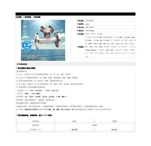
过滤器>>T型过滤器>>T型过滤器产品名称:T型过滤器产品型号:ST34产品口径:DN150-500产品压力:0.6~10.0Mpa产品材质:铸钢、不锈钢、合金钢等产品概括:生产标准:国家标准GB、机械标准JB、化工标准HG、美标API、ANSI、德标DIN、日本JIS、JPI、英标BS生产。
阀体材质:铜、铸铁、铸钢、碳钢、WCB、WC6、WC9、20#、25#、锻钢、A105、F11、F22、不锈钢、304、304L、316、316L、铬钼钢、低温钢、钛合金钢等。
工作压力1.0Mpa-50.0Mpa。
工作温度:-196℃-650℃。
连接方式:内螺纹、外螺纹、法兰、焊接、对焊、承插焊、卡套、卡箍。
驱动方式:手动、气动、液动、电动。
产品详细信息T型过滤器主要技术参数:适用的物料有:①化工、石油化工生产中的弱腐蚀性物料,如:水、氨、油品、烃类等。
②化工生产中的腐蚀性物料,如:烧碱、纯碱、浓稀硫酸、碳酸、醋酸、酯酸等。
③制冷中的低温物料,如:液甲烷、液氨、液氧和各种冷剂。
④轻工食品、制药生产中卫生要求的物料,如:啤酒、饮料、乳制品、粮浆医药用品等。
⑤各种特殊工艺的高效精密过滤器等。
工作温度(℃):碳钢:-30~380℃,不锈钢:-80~450℃。
工作压力(MPa):0.6~5.0MPa。
壳体材质:A3、SS304、SS304L、SS316、SS316L、衬PP、H62等。
密封材质:耐油石棉橡胶、丁腈橡胶、聚四氟乙烯。
粗过滤滤芯材质:滤框滤网均为不锈钢。
过滤滤芯材质:钛合金烧结滤芯,不锈钢折叠滤芯、聚四氟折叠滤芯、聚丙烯折叠滤芯、金属纤维烧结管毡、陶瓷。
法兰标准:HG20592~97PN1.0当客户需用GB、SH、HGJ、JB或ANSI、JIS等标准或改变压力等级时,请在订货合同中注明。
T型过滤器制造、检测标准:执行GB150标准壳体材质碳钢不锈钢滤芯材质不锈钢工作温度(℃)-30~380-80~450<<阀门采购流程及注意事项>>:1、询价应当找专业符合阀门产品的厂家,尽量找有实力的品牌或合作过的厂家,避免技术不成熟、价格昂贵、质量不过关、货期时间长。
特殊管件中英文对照
管道特殊件Piping Specialty1.7.1 管道特殊件(组件)粗滤器strainer过滤器filter临时粗滤器(锥型)temporary strainer (cone type)y 型粗滤器y-type strainerT型粗滤器T-type strainer永久过滤器permanent filter丝网粗滤器gauze strainer洗眼器及淋浴器eye washer and shower视镜sight glass阻火器flame arrester喷嘴;喷头spray nozzle取样冷却器sample cooler消 声 器silencer膨胀节expansion joint波纹膨胀节bellow expansion joint单波single bellow双波double bellow多波multiple bellow压力平衡式膨胀节pressure balanced expansion带铰链膨胀节hinged expansion joint轴向位移型膨胀节axial movement type expansion joint 自均衡膨胀节(外加强环)self-equalizing expansion joint 带接杆膨胀节tied expansion joint万向型膨胀节universal type expansion joint球形补偿器ball type expansion joint填函式补偿器slip type (packed type) expansion joint单向滑动填料函补偿器single actionpacked slip joint1.7.2 管道特殊元件Piping Special Element软管接头hose connection (HC)快速接头quick coupling金属软管metal hose橡胶管rubber hose挠性管flexible tube鞍形补强板reinforcing saddles补强板reinforcement pad特殊法兰special flange漏斗funnel排液环drip ring排液漏斗drain funnel插板blank垫环spacer8字盲板spectacle blind; figure 8 blind限流孔板restriction orifice爆 破片rupture disk法兰盖贴面protective disc费托立克接头victaulic coupling1.8 端部连接End Connection法兰端flanged end坡口端beveled end (BE)对焊端butt welded end平端plain end (PE)承插焊端socket welding end螺纹端threaded end (TE)承口bell end焊接端welding end法兰连接(接头)flanged joint对焊连接(接头)butt welded joint螺纹连接,管螺纹连接threaded joint, pipe threaded joint 锥管螺纹密封焊连接seal-welded taper pipe threaded joint 承插焊连接(接头)socket welded joint承插连接(接头)bell and spigot joint环垫接头ring joint (RJ)万向接头universal joint软钎焊连接(接头)soldered joint搭接接头,松套连接lapped joint外侧厚度切斜角bevel for outside thickncss内侧厚度切斜角bevel for inside thickness内外侧厚度切斜角bevel for combined thickness法兰式的flanged (FLGD)对焊的butt welded (BW)螺纹的threaded (THD)承插焊的socket welded (SW)小端为平的small end plain (SEP)大端为平的large end plain (LEP)两端平both ends plain (BEP)小端带螺纹small end thread (SET)大端带螺纹large end thread (LET)两端带螺纹both end thread (BET)一端带螺纹one end thread (OET)支管连接branch connection焊接支管branch pipe welded directly to the run pipe。
1寸T型过滤器技术规格书
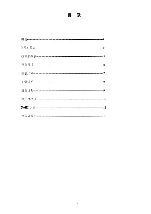
目录概述--------------------------------------------------------------------------4 型号对照表------------------------------------------------------------------4 技术参数表------------------------------------------------------------------5 外型尺寸---------------------------------------------------------------------6 安装尺寸---------------------------------------------------------------------7 安装说明---------------------------------------------------------------------9 清洗说明---------------------------------------------------------------------9 出厂合格证------------------------------------------------------------------10 RoHS认证-------------------------------------------------------------------11 设备分解图------------------------------------------------------------------12概述“ T”手动过滤器是AMIAD公司新开发的一种过滤器,根据滤网尺寸多样,过滤器的过滤精度可达500-22微米。
外面的污水通过进水管自内而外通过滤网,水通过滤网由内至外流出时杂质积累在滤网的内表面,并引一定的水头损失。
Parker 12AT 50AT、80AT 80UT系列转动过滤器说明说明书
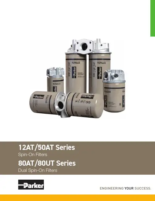
212AT/50AT80AT/80UT SeriesSpin-On FiltersApplications for Spin-On Filters• Mobile Equipment • Hydrostatic Drives • Industrial Power Units • Reservoir BreathersMounting•for flexibilityGauges/Switches • Identifies element condition during operation• No mess, oil is contained inside • Easy to handle • Single anddouble length filters for longer lifePorts• Both NPT and SAEstraight thread connections available. SAE Code 61 Flange on 80AT.Interchangeability • Parker canisters fit manycompetitors' heads. Contact Hydraulic & Fuel Filtration Division, search the Par<>Fit Toolkit at , or download our app.Parker’s latest range of Spin-On filter technology provides users withreliable performance in a lightweight, compact and cost effective package. These solutions provide protection to critical system components in a variety of low pressure applications.In addition to increased flow rates, Parker has expanded the product family to include new filter head configurations and flanged porting along withconsistency in filter element condition options.Recognized as a leader in product quality, Parker applies the latest in designand manufacturing techniques to deliver on our promise.Spin-On filters can be used in suction and return line filterapplications with pressures to 150 psi (10.3 bar).Improving system fluid cleanliness levels, providing better cold start performance and meeting service interval expectations are the primary objectives in the AT/UT series design. Parker filters utilize several types of filtration media to meet the demanding requirements of today’s applications.• Cellulose MediaThe original and most common media is made of naturalfibers. These twisted fibers are larger and more irregular than synthetic fibers — creating more resistance to flow or pressure drop.• Synthetic MediaThese man-made glass fibers are very uniform in size and shape — creating the least possible resistance to flow and providing improved efficiency to protect sensitive controls. • Par-Gel MediaA highly absorbent copolymer laminate with an affinity for water — allows hydraulic or lubrication fluid to pass freely but water is bonded to the media and forever removed from the system.312AT/50AT/80AT/80UT SeriesPerformanceFlow vs. Pressure LossLPM GPMP S I DB A R12AT -1 AssemblyLPMGPMP S I DB A R12AT -2 Assembly1086420LPM GPMP S I DB A R50AT -1 Assembly30252015105LPMGPMP S I DB A R30252015105LPMGPMP S I DB A R80AT -1 Assembly80UT -1 Assembly1086420LPM GPMP S I DB A R50AT -2 Assembly161412108642GPMP S I DB A RLPM181614121086420GPMP S I DB A R LPM80UT -2 Assembly80AT -2 AssemblyInstallation and Specification DataPressure Rating:Maximum AllowableOperating Pressure (MAOP): 150 psi (10.3 bar)Design Safety Factor: 2.5:1Operating Temperatures:-40ºF to 225ºF (-40ºC to 107ºC)Canister Collapse Rating:100 psid minimumCanister Condition Indicators:Gauge: Color coded 15/25 psi Gauge: Color coded vacuum Pressure Switch: Normally open 20 +/- 2 psi 5 Amps @ 24 VDC Vacuum Switch: Normally open 5" +/- 1" Hg 1.0 Amp @ 120 VAC Filter Material: Head: AluminumCanister: Low Carbon Steel Shipping Weights (approximate):Single length: 1.6 lbs.Double length: 2.7 lbs.Drawings are for reference only. Contact factory for current version.Spin-On FiltersLinear Measure: millimeterinchThread DepthDia 4Spin-On FiltersPressure Rating:Maximum AllowableOperating Pressure (MAOP): 150 psi (10.3 bar)Design Safety Factor: 2.5:1Operating Temperatures:-40ºF to 225ºF (-40ºC to 107ºC)Canister Collapse Rating:100 psid minimumCanister Condition Indicators:Gauge: Color coded 15/25 psi Gauge: Color coded vacuum Pressure Switch: Normally open 20 +/- 2 psi 5 Amps @ 24 VDC Vacuum Switch: Normally open 5" +/- 1" Hg 1.0 Amp @ 120 VAC Filter Material: Head: AluminumCanister: Low Carbon Steel Shipping Weights (approximate):Single length: 3.9 lbs.Double length: 4.8 lbs.Installation and Specification DataDrawings are for reference only. Contact factory for current version.Linear Measure: millimeterinch127.805.0357.152.2529.201.1525.401.005DiaInstallation and Specification DataPressure Rating:Maximum AllowableOperating Pressure (MAOP): 150 psi (10.3 bar)Design Safety Factor: 2.5:1Operating Temperatures:-40ºF to 225ºF (-40ºC to 107ºC)Canister Collapse Rating:100 psid minimumCanister Condition Indicators:Gauge: Color coded 15/25 psi Gauge: Color coded vacuum Pressure Switch: Normally open 20 +/- 2 psi 5 Amps @ 24 VDC Vacuum Switch: Normally open 5" +/- 1" Hg 1.0 Amp @ 120 VAC Filter Material: Head: AluminumCanister: Low Carbon Steel Shipping Weights (approximate):Single length: 11.3 lbs.Double length: 13.0 lbs.Drawings are for reference only. Contact factory for current version.Dual Spin-On FiltersLinear Measure: millimeterinchNPT Integral ThreadsGauge Port (4 places)Torque to 2-3 turns from finger tight6Ports (Both Ends) Integral Threads+1DANGER!Read and followall safety instructions.Failure to do so could resultin serious bodily injury ordeath.2. Turn off power supply topumping unit.3. Tag pumping unit out ofservice for filter change.4. Remove the old filter, whilecollecting all spilled fluid.Dispose of the old filter inaccordance with local, stateor federal regulations.5. Apply a thin film oflubricating oil to the gasketof the new filter.6. Thread new filter on the flowadapter or manifold untilthe gasket makes contact.Tighten according to filterlabel.7. Turn on fluid supply.8. Pressurize the system andcheck for leaks.WARNING! A pressuredifferential indicator mustbe installed for any systemcapable of generating morethan 25 psid across the filter.2. Filter unit must be installedusing a suitable mountingdevice or rigid piping.3. Filter unit must be installedwith flow in proper direction.4. Filter should be inspectedevery six months andchanged annually when slowflow occurs.5. Water absorbing filters- when the differentialpressure reaches 20-25 psidthe filter could be pluggedwith water and shouldbe immediately replaced.Failure to replace couldresult in internal filter ruptureresulting in water downstream.Spin-On Filters8Return Line Applications1. 25 lb bypass in flow adapterrecommended.2. Filter unit must be installedin the circuit just before thereservoir. DO NOT use ashutoff valve in the returnline for the filter that is beingchanged. A check valve isacceptable.3. Filter unit must be sizedto accept the total flowduring discharging from thecylinders and actuators.Suction Side Applications1. 3-5 lb bypass in flowadapter recommended toprevent pump cavitation.2. A vacuum gauge isrecommended to monitorfilter condition.3. Cavitation of the pump canbe a problem with the filteron the suction line. Alwaystry to minimize restriction byover sizing the filter, or byusing a microglass media.6. If water stoppage issuspected, remove the waterabsorbing filter and pour thecontents in a jar. If fluid iscloudy or water separates inthe jar, the filter is most likelyplugged with water. If wateris excessive in the jar it maybe necessary to have thetank cleaned or drained priorto further use.Spin-On FiltersAccessory Parts ListIndicating Pressure Gauge (15 PSI)Indicating Pressure Gauge (25 PSI)Pressure Switch1/8-27NPTF Vacuum Switch Linear Measure: millimeterinch1/8 NPTSeals IncludedIndicating Vacuum Gauge9Spin-On FiltersReservoir BreatherSizingSelect the proper size canister for the maximum rate of reservoir draw down or air exchange rate. As a rule of thumb, clean pressure drop should be limited to 0.18 psid (5" H 2O).A pipe flange, weld collar, etc. may be used to connect the adapter kit to the reservoir. Make sure that air is not able to leak around the adapter. When mounting on the side of the reservoir, make sure the installation is above the surface of the fluid.Recommended canister change out is after 500 hours of operation.More frequent replacement may be required when operated in heavily contaminated areas such as grinding operations, primary metal mills, and on mobile equipment. Under such conditions, increase replacement frequency to every 250 hours.* 99% Removal efficiency for particles larger than the stated size in air.Graphs are for 03C canisters only. Total pressure drop across canister, adapter, and pipe may be found by adding pressure drops below:+ 1.5% for each inch of 12AT adapter or 3/4" pipe used.+ 3.0% for each 3/4" elbow used.+ 1.0% for each inch of 50AT adapter or 1-1/4" pipe used.+ 2.0% for each 1-1/4" elbow used.Typical Installations mounted on side or top of reservoirAllow 1.25" for canisterremoval clearanceLinear Measure: millimeterinch1012AT/50AT/80AT/80UT SeriesSpin-On FiltersHow T o OrderSelect the desired symbol (in the correct position) to construct a model code.Example:Notes:1. Selecting 80AT or 80UT in Box 1 requires the selection of “G” in Box 6 and “H” in box 8.2. Nominal flow rates for single length filters: 12AT - 12GPM; 50AT - 35 GPM; 80AT/80UT - 55 GPM.Replacement Canisters11Aerospace Filtration Division Greensboro, North Carolina 336 668 4444Bioscience & Water Filtration Division Bioscience Filtration Oxnard, California877 784 2234Water PurificationCarson, California310 608 5600Engine Mobile Aftermarket Division Kearney, Nebraska308 234 1951Engine Mobile Original Equipment Division Modesto, California209 521 7860HVAC Filtration Division Industrial Gas Filtration &Generation DivisionLancaster, NY800 343 4048Industrial ProcessFiltration DivisionMineral Wells, T exas940 325 2575Bioscience EngineeringFiltration Division EMEABirtley, United Kingdom+44 (0) 191 410 5121Engine Mobile FiltrationDivision EMEADewsbury, United Kingdom+44 (0) 1924 487 037Gas Separation &Filtration Division EMEAT eam Valley, United Kingdom+44 (0) 191 402 9000Australia Filtration DivisionCastle Hill, Australia+61 2 9634 7777China Filtration DivisionShanghai, China+86 21 2067 2067India Filtration DivisionChennai, India+91 22 4391 0700Korea Filtration DivisionHwaseon City, Korea+82 31 359 0852Latin America Filtration DivisionSao Paulo, Brazil+55 12 4009 3500Parker Filtration Group。
MT型滤筒除尘器说明书
4、与其它类型的袋式除尘器相比较,具有体积小、重量轻(仅 为1/2~1/4),维护简便,寿命长(工况条件下1~2年)。
三、工作原理本除尘器一般为负压运行,含尘气体由进风口进入箱体,在折叠 滤筒内负压作用下,含尘气体从筒外透过滤料进入滤筒内,进入清洁 室从出风口排出,当粉尘小颗粒弥散在滤料表面上越积越多,阻力越 来越大,达到设定值时(也可时间设定),脉冲阀打开压缩空气直接 喷入滤筒中心,对滤筒进行顺序脉冲清灰,使滤筒外壁尘块层被崩溃 跌落,有效使粉尘进入灰斗,完成了清灰再生功能,使其恢复低阻运 行。
四、滤筒除尘器的型号及其含义MT 大面积滤筒除尘器脉冲反吹M过滤面积 滤筒排数过滤材质MT小面积滤筒除尘器:120过滤面积过滤材质脉冲反吹五、滤筒规格及参数小面积滤筒除尘器滤筒规格及参数大面积滤筒除尘器滤筒规格及参数注:处理风量为过滤风速0.6m/min情况下。
此滤筒为进口滤筒型号为UTA637、BHA聚酯合成滤料作防油防火表面后处理。
六、MT型除尘器选型参数MT小面积滤筒除尘器:MT大面积滤筒除尘器MT大面积滤筒除尘器九、电气部分:上电:合闸前先检查柜体并将所有的断路器分闸,然后将总闸合上,然后将电气柜中的热继电器合上,而后将断路器逐个合闸,最后把PLC电源合闸' 开机前检查首先保证各个限位没有被挪动、气压是否正常(如果气压不稳定不可开机工作),机械上没有工件和其它物件。
部分除尘器带有一个燃烧器,该燃烧器由送风风机和燃烧器分线箱组成。
当除尘给燃烧器的信号停止时,燃烧器停止,风机脉冲一次后停止。
除尘给燃烧器的信号结束,送风风机由设定的延时一段时间停止。
没有燃烧器不考虑。
除尘分为三个档位:1、手动位为单个控制系统,按下即启动,再次按下停止。
1)首先启动风机,待风机正常启动完毕,可启动脉冲控制,脉冲控制按照脉冲仪设定的参数依次循环,具体可参照脉冲控制仪说明书。
2)排灰和振动属于独立的部分,当排灰启动后,你适当的启动振动,防止除尘斗部分仍有粘砂。
TT系列陶瓷过滤机说明书2015年
3、 规格参数
3.1 TT 系列陶瓷过滤机基本参数
名称
过滤机参数
TT-3 TT-8 TT-12 TT-16 TT-20 TT-24 TT-30 TT-36 TT-
96
120 96 120 144 180 180 240
圆盘数量(圈) 3 4
- 1-
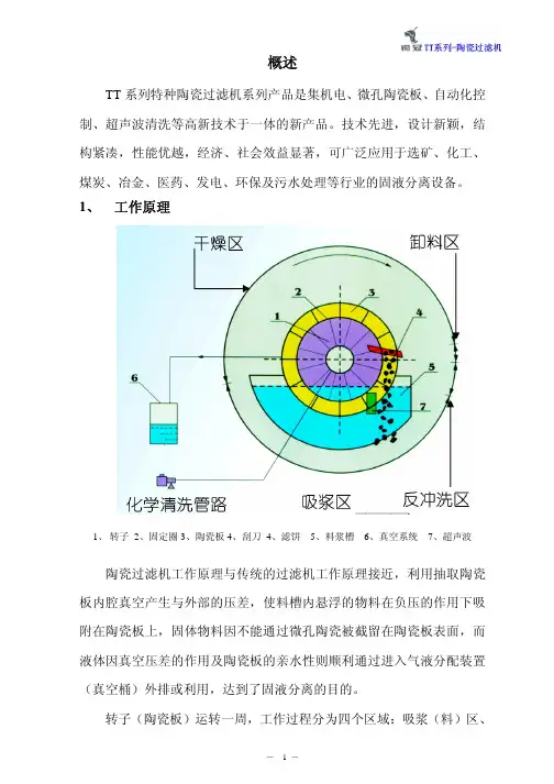
干燥区、卸料区、清洗区,反复循环。
1.1 滤饼形成(吸料区)
工作开始时,浸没在料浆槽的陶瓷板在真空的作用下,表面形成一 层较厚的颗粒堆积层,滤液通过陶瓷板过滤至分配阀到达真空桶。
1.2 滤饼干燥(干燥区)
转子载着滤饼通过吸浆区到干燥区,滤饼在真空作用下继续脱水干 燥。
1.3 滤饼剥离(卸料区)
反冲洗压力表 手阀
稀
酸
稀
泵
酸
桶
过滤器
管道泵 手阀 气阀
接水箱或 自来水
2.3.1 反冲洗装置 反冲洗装置由调节手阀、过滤器、反冲洗管道等组成,对每一个循环
的反冲洗区的陶瓷板进行由内向外冲洗,保证在每一个循环中陶瓷板微
孔得到疏通,在开车及联合清洗时工作。
反
冲
洗
槽体
分配阀
反冲洗压力表 手阀
管道泵 手阀 气阀
4、安装条件及注意事项
4.1 安装条件 正常状态下陶瓷过滤机的设计采用从浓密机直接进料(或泵进行输
送),因此进料管的敷设要有一定的斜度(一般情况下为 1∶10)。 设备布置工艺图所示位置仅供现场安装时参考用。如遇与现场相冲
突时,可根据现场的情况以不影响陶瓷过滤机必要工作条件及工艺为前 提。
浓酸桶的安装位置应便于槽车卸酸,其供酸方式需根据现场的具体 情况选择自流或磁力泵供酸。如采用自流,浓酸桶的标高应高于陶瓷过 滤机稀酸桶最高点 1 米。并且保证周围有足够的安全空间,有安全提示、 护栏及排放沟。
海滩S166T高速沙滤器产品说明书
Your Hayward S166T high-rate sand filter is a high performance, totally corrosion-proof filter that blends superior flow characteristics and features with ease of operation. It represents the very latest in high-rate sand filter technology. It is virtually foolproof in design and operation and when installed, operated and maintained according to instructions, your filter will produce clear, sparkling water with only the least attention and care. HOW IT WORKSYour filter uses special filter sand to remove dirt particles from pool water. The sand is loaded into the filter tank and functions as the permanent dirt removing media. The pool water, which contains suspended dirt particles, is pumped through your piping system and is automatically directed by the patented filter control valve to the top of the filter tank. As the pool water is pumped through the filter sand, dirt particles are trapped by the sand bed, and filtered out. The cleaned pool water is returned from the bottom of the filter tank, through the control valve and back to the pool through the piping system. This entire sequence is continuous and automatic and provides for total recirculation of pool water through your filter and piping system.After a period of time, the accumulated dirt in the filter causes a resistance to flow, and the flow diminishes. This means it is time to clean (backwash) your filter. With the control valve in the backwash position, the water flow is automatically reversed through the filter so that it is directed to the bottom of the tank, up through the sand, flushing the previously trapped dirt and debris out the waste line. Once the filter is backwashed (cleaned) of dirt, the control valve is manually resequenced to Rinse, and then Filter, to resume normal filtering. INSTALLATIONOnly simple tools (screwdriver and wrenches), plus pipe sealant for plastic adapters, are required to install and/or service filter.The filter should be placed on a level concrete slab, very firm ground, or equivalent as recommended by your pool dealer. Position the filter so that the piping connections, control valve and winter drain are convenient and accessible for operation, servicing and winterizing.Your filter is supplied complete with an optional pump mounting base which is pre-drilled for use with Hayward Power-Flo LX series pumps. The pump to filter connecting hoses supplied will accommodate Power-Flo LX pumps used with the mounting base, and Max-Flo or Super Pump installed at surface level. To connect pump to filter:Screw straight adapter, using Teflon pipe sealanttape or Permatex No. 2, securely into pumpdischarge. (Do not overtighten.)Screw elbow adapter, using Teflon pipe sealanttape or Permatex No. 2, securely into opening incontrol valve marked PUMP. (Do not overtighten.)Elbow should point just over RETURN opening. 1.2.a.b.IS166TN2-00PUMP MOUNTINGBASE (S164C)33”(84 cm)SPECIFICATIONSMODEL NUMBER EFFECTIVE FILTRATION AREADESIGN FLOW RATE MAXIMUM WORKINGPRESSURE REQUIRED CLEARANCEMEDIA REQUIRED FT 21.4S166TM 20.13GPM 35LPM 133PSI 50BAR 3.45INCH 18INCH 18MM 457MM 457FILTER SAND*0.45-0.55LBS 100KGS 45ABOVE SIDE TYPE AMOUNT *Also known as No. 20 or No. 1/2 Silica Sand.NOTE: ANSI/NSPI-4 Article V, standard for above-groundand on-ground pools, advises that components such as the filtration system, pumps and heater be positioned so as to prevent their being used as a means of access to the pool by young children.PARTS Model S166TS166T1575XS S166T1575XSN2REF.NO.123456891011121314*15*16*17*18**19**NO.REQ’D.11111111011112112111PART NO.SP071113ECX27081GMX600F GMX600NS SX202S SX164DA SX200Q SX180G SX180H SX164B SX164C ECX1108A SX160Z5SPX1105Z4ECX18028SPX1091Z2N2SABG SX164DAN2KITDESCRIPTIONVari-Flo Control Valve Assembly Pressure Gauge Valve/Tank O-Ring Flange Clamp (Valve-Tank)Sand ShieldLateral Assembly with Center Pipe Filter Tank with Skirt,Complete Lateral Assembly Lateral Gasket Drain CapFilter Support Stand (Skirt)Pump Base5/16”x 3/4”Mounting Screw Kit 1-1/2”Hose1-1/2”Elbow Adapter Hose Clamp1-1/2”Straight Hose Adapter Nature 2CanisterFolding Umbrella Lateral Assembly w/Center Pipe for Nature 2Canister*Furnished with PAK or System only.**Included only on filters supplied with SwimPure CanisterSX164AA17STOP here and load media per instructions (No. 3).Place hose clamps on clear hose and fit hose overstraight and elbow adapters and secure with clamps. Ifit is difficult to fit hose over the adapters, place hose inhot water for several minutes.NOTE:To prevent breakage and damage to pump and control valve, use only pipe sealants specifically formulated for plastics. Do not overtighten fittings or adapters.Loading sand media. Filter sand media is loaded through the top opening of the filter.Loosen flange clamp and remove Filter Control Valve(if previously installed).Cap internal pipe with sand shield to prevent sandfrom entering it. Be sure pipe is securely in place inbottom underdrain hub.We recommend filling tank approximately 1/2 way withwater to provide a cushioning effect when the filtersand is poured in. This helps protect the underdrainlaterals from excessive shock. (Be sure the winterdrain cap is securely in place on drain pipe.) Note:Check to confirm all laterals are in the downposition before loading with sand. (See Figure A onPage 2.)Carefully pour in correct amount and grade of filtersand, as specified. (Be sure center pipe remainscentered in opening). Sand surface should be leveledand should come to about the middle of the filter tank.Remove sand shield from center pipe.NOTE: If your sand filter is equipped with the SwimPure system or you are installing the SwimPure Retrofit Kit, then please follow the steps in the Instruction Sheet included in the SwimPure carton.Assemble Filter Control Valve to filter tank.Wipe filter flange clean.To install clamp, loosely preassemble both halves of theclamp with one screw and one nut, turning the nut twoor three times. Place clamp assembly on the filter neck.Insert filter control valve (with valve/flange O-ring inplace) into the tank neck, taking care that the centerpipe slips into the hole in the bottom of the valve.Install clamp around tank and valve flange andassemble second screw and nut. Tighten both sides ofclamp alternately and evenly. Make sure you tightenjust enough so that the valve may be rotated on thetank for final positioning.Carefully screw the pressure gauge, with pipe tape,into 1/4” tapped hole in valve body. Do not overtighten.Connect pump to control valve opening marked“PUMP” according to the instructions.Tighten both sides of clamp alternately and evenly. Usea correctly sized large screw driver and tighten firmlyto obtain a good seal.Please be sure to place vinyl protector caps over ends ofscrews.Make return to pool pipe connection to control valve opening marked RETURN and complete other necessary plumbing connections, suction lines to pump, waste, etc.Make electrical connections to pump per pump instructions. Be sure all circuits are protected by aproperly-sized ground fault circuit interrupter (GFCI).To prevent water leakage, be sure winter drain cap is securely in place and all pipe connections are tight. NOTE: If you have installed a SwimPure system, then please refer to Step 2 in the SwimPure Instruction Sheet (“Balance the Pool Water”).INITIAL START-UP OF FILTERBe sure correct amount of filter sand media is in tank and that all connections have been made and are secure.Depress Vari-Flo control valve handle and rotate to BACKWASH position. (To prevent damage to control valve seal, always depress handle before turning.)Prime and start pump according to pump instructions allowing the filter tank to fill with water. CAUTION: All suction and discharge valves must be open when starting the pump. Failure to do so could cause severe personal injury and/or property damage.Once water flow is steady out the waste line, run the pump for at least 1 minute. The initial backwashing of the filter is recommended to remove any impurities or fine sand particles in the sand media.Turn pump off, set valve to RINSE position. Start pump and operate until water in sight glass is clear—about 1/2 to 1 minute. Turn pump off, set valve to FILTER position and restart pump. Your filter is now operating in the normal filter mode, filtering particles from the pool water.Adjust pool suction and return valves to achieve desired flow. Check system and filter for water leaks and tighten connections, bolts, nuts, as required.Note the initial pressure gauge reading when the filter is clean. (It will vary from pool to pool depending upon the pump and general piping system). As the filter removes dirt and impurities from the pool water, the accumulation in the filter will cause the pressure to rise and flow to diminish. When the pressure gauge reading is 6-8 lbs.(2.7-3.6 kgs.) higher than the initial “clean” pressure younoted, it is time to backwash (clean) the filter (see BACKWASH under Filter Control Valve Functions). NOTE: During initial clean-up of the pool water, it may be necessary to backwash frequently due to the unusually heavy initial dirt load in the water.CAUTION: To prevent unnecessary strain on piping system and valving, always shut off pump before switching Filter Control V alve positions.To prevent damage to the pump and filter and for proper operation of the system, clean pump strainer and skimmer baskets regularly.FILTER CONTROL VALVE FUNCTIONSFILTER–Set valve to FILTER for normal filtering. Also use for regular vacuuming.BACKWASH–For cleaning filter. When filter pressure gauge rises 6-8 lbs. (2.7-3.6 kgs.) above start-up (clean pressure):Stop the pump, set valve to BACKWASH. Start pump and backwash, approximately 2 minutes or less, depending on dirt accumulation, until water in sight glass is clear. Proceed to RINSE.3.a.b.c.d.4.a.b.c.d.e.f.g.h. 5. 6.1. 7. 2.3.c.4.5.6.RINSE—After backwashing, with pump off, set valve to RINSE. Start pump and operate for about 1/2 to 1 minute. This ensures that all dirty water from backwashing is rinsed out of the filter to waste, preventing possible return to the pool. Stop pump, set valve to FILTER and start pump for normal filtering.WATER—To bypass filter for draining or lowering water level and for vacuuming heavy debris directly to waste.RECIRCULATE—Water is recirculated through the pool system, bypassing the filter.CLOSED—Shuts off flow from pump to filter.VACUUMING—Vacuuming can be performed directly into the filter. When vacuuming heavy debris loads, set valve to WASTE position to bypass the filter and vacuum directly out to waste.WINTERIZINGCompletely drain tank by unscrewing drain cap at base of filter tank. Leave cap off during winter.Depress Vari-Flo control valve handle and rotate so as to set pointer on valve top between any two positions. This will allow water to drain from the valve. Leave valve in this “inactive” position.Drain and winterize pump according to pump instructions.SERVICE & REPAIRSConsult your local authorized Hayward dealer or service center.No returns may be made directly to the factory without theexpressed written authorization of Hayward Pool Products, Inc.PROBLEM SOLVING LISTLOW WATER FLOWSHORT FILTER CYCLES POOL WATER WON’T CLEAR UP Check skimmer and pump strainer baskets for debris.Check for restrictions in intake and discharge lines.Check for air leak in intake line (indicated by bubbles returning to pool).Backwash filter.Check for algae in pool and superchlorinate as required.Be sure chlorine and pH levels are in proper range (adjust as required).Check surface of filter sand for crusting or caking (remove 1”of sand if necessary).Check chlorine, pH and total alkalinity levels and adjust as required.Be sure flow rate through filter is sufficient.Operate filter for longer periods.Be sure Vari-Flo valve is set on “Filter” position.1.2.3.4. 1.2.3. 1.2.3.4.REMEDYPOOL CHEMISTRY GUIDELINESACTION REQUIRED TO CORRECT POOL CHEMISTRY TO RAISETO LOWERSUGGESTED POOL CHEMISTRY LEVELS pHTOTAL ALKALINITYCHLORINE (UNSTABILIZED)CHLORINE (STABILIZED)CHLORINE STABILIZER (Cyanuric Acid)7.2 to 7.6100 to 130 ppm 0.3 to 1.0 ppm 1.0 to 3.0 ppm 40 to 70 ppmAdd Soda AshAdd Sodium Bicarbonate Add Chlorine Chemical Add Chlorine Chemical Add StabilizerAdd Muriatic Acid or Sodium BisulphateAdd Muriatic Acid No action - chlorine will naturally dissipate No action - chlorine will naturally dissipate Dilution - partially drain & refill pool with water that has not been treated with Cyanuric Acid.©2000 Hayward Printed in U.S.A.Rev. 11/00PLEASE REALIZE . . .Pure, clear swimming pool water is a combination of two factors–adequate filtration and proper water chemistry balance.One without the other will not give the clean water you desire.Your filter system is designed for continuous operation.However, this is not necessary for most swimming pools. You can determine your filter operation schedule based on your pool size and usage. Be sure to operate your filtration system longenough each day to obtain at least one complete turnover of your pool water.To properly sanitize your pool, maintain a free chlorine level of 1 to 3 ppm and a pH range of 7.2 to 7.6. Insufficient chlorine or an out of balance pH level will permit algae and bacteria to grow in your pool and make it difficult for your filter to properly clean the pool water.1.2.3.。
MT型滤筒除尘器说明书
九、电气部分:上电:合闸前先检查柜体并将所有的断路器分闸,然后将总闸合上,然后将电气柜中的热继电器合上,而后将断路器逐个合闸,最后把PLC电源合闸。
开机前检查首先保证各个限位没有被挪动、气压是否正常(如果气压不稳定不可开机工作),机械上没有工件和其它物件。
部分除尘器带有一个燃烧器,该燃烧器由送风风机和燃烧器分线箱组成。
当除尘给燃烧器的信号停止时,燃烧器停止,风机脉冲一次后停止。
除尘给燃烧器的信号结束,送风风机由设定的延时一段时间停止。
没有燃烧器不考虑。
除尘分为三个档位:1、手动位为单个控制系统,按下即启动,再次按下停止。
1)首先启动风机,待风机正常启动完毕,可启动脉冲控制,脉冲控制按照脉冲仪设定的参数依次循环,具体可参照脉冲控制仪说明书。
2)排灰和振动属于独立的部分,当排灰启动后,你适当的启动振动,防止除尘斗部分仍有粘砂。
2、自动为当选择自动位置时,风机自动启动,排灰、脉冲每15分钟(以调试人员设定时间为准)循环一次。
自动启动或者停止脉冲、排灰各一次。
1)自动启动首先需要关闭调风门,待风机启动后打开调风门。
没有电动调风门即直接启动风机。
2)自动启动风机后,开启振动和脉冲装置各运行一次,运行时间由PLC设定(具体由现场编程人员设定)。
3)自动运行中,在设定时间(PLC内部设定)到达后首先脉冲一个循环,然后排灰运行设定时间后停止。
3、在联动状态下,风机自动启动,排灰、脉冲每15分钟(以调试人员设定时间为准)循环一次(以调试人员设定时间为准。
自动启动或者停止脉冲、排灰各一次。
联动转台下,当PLC接受到外界给的联动信号,除尘器参照自动运行。
包含脉冲仪的除尘器,需要对照脉冲仪说明书进行调整,可调整脉冲宽度、脉冲间隔、脉冲循环时间,一般脉冲宽度为0.3-0.5秒,间隔为5-8秒,循环时间由由PLC或者脉冲控制仪设定,根据除尘的大小,循环时间都不一样。
注意:●为保证人身安全及设备的正常运行,在使用本电气控制系统前请详细阅读使用说明,充分理解各项内容,并按使用说明要求正确使用,不正确的使用,将会引起事故和降低系统的寿命。
TT系列陶瓷过滤机说明书2015年
反冲洗压力表 手阀
稀
酸
稀
泵
酸
桶
过滤器
管道泵 手阀 气阀
接水箱或 自来水
2.3.1 反冲洗装置 反冲洗装置由调节手阀、过滤器、反冲洗管道等组成,对每一个循环
的反冲洗区的陶瓷板进行由内向外冲洗,保证在每一个循环中陶瓷板微
孔得到疏通,在开车及联合清洗时工作。
反
冲
洗
槽体
分配阀
反冲洗压力表 手阀
管道泵 手阀 气阀
分配阀端
1、搅拌架 2、搅拌轴 3、搅拌电机 4、电机支座 5、联轴器 6、轴承座 7、支座 8、吊轴
- 5-
2.3 清洗系统
清洗系统分反冲洗装置、超声波清洗装置和化学清洗(酸洗)装置, 三者工作的目的是为了保障陶瓷板微孔通畅,保持陶瓷板的高效率的运 行。
分配阀
反 冲 洗
超 声 波
槽体
浓 酸 桶
气阀 接自来水
概述
TT 系列特种陶瓷过滤机系列产品是集机电、微孔陶瓷板、自动化控 制、超声波清洗等高新技术于一体的新产品。技术先进,设计新颖,结 构紧凑,性能优越,经济、社会效益显著,可广泛应用于选矿、化工、 煤炭、冶金、医药、发电、环保及污水处理等行业的固液分离设备。
1、 工作原理
1、 转子 2、固定圈 3、陶瓷板 4、刮刀 4、滤饼 5、料浆槽 6、真空系统 7、超声波
陶瓷过滤机工作原理与传统的过滤机工作原理接近,利用抽取陶瓷 板内腔真空产生与外部的压差,使料槽内悬浮的物料在负压的作用下吸 附在陶瓷板上,固体物料因不能通过微孔陶瓷被截留在陶瓷板表面,而 液体因真空压差的作用及陶瓷板的亲水性则顺利通过进入气液分配装置 (真空桶)外排或利用,达到了固液分离的目的。
(完整版)管道过滤器选型大全1
th i n gs i n t h e i r be i n g a r eg oo管道过滤器的种类与用途一 、 Y 型过滤器Y 型过滤器属于管道粗过滤器,可用于液体、气体或其他介质大颗粒物过滤,安装在管道上能除去流体中的较大固体杂质,使机器设备(包括压缩机、泵等)、仪表能正常工作和运转,达到稳定工艺过程,保障安全生产的作用。
当流体进入置有一定规格滤网的滤筒后,其杂质被阻挡,而清洁的滤液则由过滤器出口排出,当需要清洗时,只要将可拆卸的滤筒取出,处理后重新装入即可,因此,使用维护极为方便。
我公司所生产的Y 型过滤器可根据客户具体要求(特殊压力、特殊口径)定制。
Y 型过滤器具有制作简单、安装清洗方便、纳污量大等优点。
安装与维护:1、Y型过滤器可以水平安装,也可以垂直安装,进出口方向与阀体上的箭头方向应保持一致。
2、过滤器工作一段时间后,滤芯内沉淀了一定的杂质,这时压力降增大,流速会下降,需及时清除过滤器芯内的杂质3、清洗杂质时,特别注意过滤芯上的不锈钢钢丝网不能变形或损坏,否则,再装上去的过滤器,过滤后介质的纯度达不到设计要求,压缩机、泵、仪表等设备会遭到破坏。
4、如发现不锈钢钢丝网变形或损坏,需马上更换。
二、篮式过滤器篮式过滤器主要由接管、筒体、滤篮、法兰、法兰盖及紧固件等组成。
安装在管道上能除去流体中的较大固体杂质,使机器设备(包括压缩机、泵等)、仪表能正常工作和运转,达到稳定工艺过程,保障安全生产的作用当液体通过筒体进入滤篮后,固体杂质颗粒被阻挡在滤篮内,而洁净的流体通过滤篮、由过滤器出口排出。
当需要清洗时,旋开主管底部螺塞,排净流体,拆卸法兰盖,清洗后重新装入即可。
因此,使用维护极为方便。
goodforsoatimeandA安装与维护:1、篮式过滤器一般水平安装,进出口方向与阀体上的箭头方向应保持一致。
2、过滤器工作一段时间后,滤芯内沉淀了一定的杂质,这时压力降增大,流速会下降,需及时清除过滤器芯内的杂质。
- 1、下载文档前请自行甄别文档内容的完整性,平台不提供额外的编辑、内容补充、找答案等附加服务。
- 2、"仅部分预览"的文档,不可在线预览部分如存在完整性等问题,可反馈申请退款(可完整预览的文档不适用该条件!)。
- 3、如文档侵犯您的权益,请联系客服反馈,我们会尽快为您处理(人工客服工作时间:9:00-18:30)。
T型过滤器
使用说明书
中国·乐山市热工仪表有限公司
一、用途及特点
T型过滤器是输送介质的管道系统不可缺少的一种过滤装置,T型过滤器通常安装在减压阀、泄压阀、定水位阀或其它设备的进口端,用来清除介质中的杂质,以保护阀门及设备的正常使用。
T型过滤器具有结构先进,阻力小,排污方便等特点。
二、主要技术参数
公称压力:PN1.6MPa~15.0Mpa
公称通径:DN15~450㎜
适用介质:水、油、气体等
过滤精度:通水网为18~30目,通气网为40~100目,通油网为100~480目。
工作温度:≤200℃
法兰标准:JB、GB、HG
壳体材质:20G.304
滤筐、滤网材质:304
密封材质:耐油石棉橡胶、聚四氟乙烯、丁腈橡胶等
执行标准:Q/20696377-7.4-2011
三、安装与维护
1、根据过滤器的使用范围合理地使用。
2、安装前应将管道内的焊渣、杂物清除干净,以免损坏过滤器。
3、安装时应按过滤器的箭头方向进行。
4、过滤器的运行及维护系统最初工作一段时间后(一般不超过一周),应进行清洗,
以清除系统初始运行时积聚在滤网上的杂质污物。
在此后,须定期清洗。
清洗次数依据工况条件而定。
若过滤器不带排污丝堵,则清洗过滤器时要将滤网限位器以及滤网拆下。
警告:每次维护、清洗前,应将过滤器与带压系统隔离。
清洗后,重新安装时要使用新的密封垫。
5、过滤器使用中,应定期检查是否工作正常,发现异常情况,应立即消除,以免
造成事故。
6、长期存放时,应置于通风干燥处,并定期检查和保养。
四、定货须知
为了保证提供的产品能满足贵公司(厂)的使用要求,请按以下要求提供必要的参数:
1、产品型号
2、公称压力
3、公称通径
4、工作介质
5、工作温度
6、法兰标准
7、结构长度(有要求时)
五、简图。