智能水泵变频器说明书
恒亚机电全自动冷热水变频自吸泵说明书

恒亚机电全自动冷热水变频自吸泵说明书本说明书为恒亚机电全自动冷热水变频自吸泵的使用指南,旨在为用户提供相关产品的操作、维护和保养方面的知识。
一、产品概述:恒亚机电全自动冷热水变频自吸泵是一种高效、环保的水泵设备,适用于供热、供冷、冷热水循环和工业冷却等领域。
该水泵由高品质材料制成,具有自动控制和自吸功能,可有效提高水泵性能,降低能源消耗。
二、产品特点:1. 自动控制:该水泵设备配备了先进的自动控制系统,可实现自动启停,稳定运行。
用户可根据需要设置工作参数,并通过操作面板进行监控。
2. 变频电机:采用变频电机的设计,可以根据实际负荷情况自动调节运行频率,提高能效,延长使用寿命。
3. 自吸功能:具备自吸功能,无需额外加水,方便快捷进行启动操作。
4. 高效节能:该水泵设备采用高效率电机和优化的流体设计,有效降低能耗,节约能源。
5. 低噪音:优化设计的水泵结构和降噪措施,使其运行时噪音降至最低,避免干扰周围环境。
三、使用方法:1. 安装及连接:首先确保水泵处于平稳的地面上,然后按照安装图纸的要求进行安装。
根据工作环境和使用要求,选择合适的连接方式(旋转式管接头、脱盖式法兰等)。
2. 电气连接:根据水泵电控柜上的电气接线图,完成电气部分的连接,注意接线的可靠性和正确性,确保水泵能够正常工作。
3. 启动:按下启动按钮,水泵将开始自动启动。
观察指示灯和操作面板上的相关参数以确保水泵正常工作。
4. 运行监控:定期观察操作面板上的工作参数,并定期进行维护和保养工作,确保水泵的正常运行。
保持水泵周围环境清洁,注意防水、防尘和防腐。
四、注意事项:1. 请勿超过水泵额定功率或流量范围进行操作,以免损坏设备。
2. 定期检查电气设备的接线,确保电气连接可靠,避免潮湿环境导致的电器故障。
3. 遇到异常情况(如发生噪音、温度异常等),请立即停止使用并联系专业技术人员进行维修。
4. 禁止水泵在没有液体介质的情况下干运行,以免损坏机械密封件。
8100智能水泵变频器说明书(130-190)-2015-09-08

◎交流输入电源不能接到变频器输出端子 U、V、W 上,否则将导致变频器损坏并且不能 享受保修服务。 ◎不能对变频器进行耐压测试,否则将导致变频器损坏。 ◎变频器的主回路端子配线和控制回路配线应分开布线或垂直交叉,否则将会使控制信 号受干扰。 ◎主回路端子的接线电缆应使用带有绝缘套管的线鼻。 ◎当变频器和电机之间的电缆长度超过 50 米时,建议使用输出电抗器以保护变频器和电 机。
1.2 指示灯说明
◆ 运行:( 常亮 ):运行指示; ( 闪烁 ):休眠停机指示。 ◆ 停止: 停机指示(待机指示)。 ◆ 报警 1:控制器故障报警。 ◆ 报警 2:管网水压异常报警。
- 06 -
8100 系列
1.3 按键操作说明 三级菜单分别为:
① 功能码组号(一级菜单) ② 功能码标号(二级菜单) ③ 功能码设 定值(三级菜单)
8100 系列
目 录
第一章 操作面板说明 .......................06
1.1 操作面板示意图 ..........................06 1.2 指示灯说明 ..............................06 1.3 按键操作说明 ............................07 1.4 压力设置说明 ............................08
- 04 -
■ 运行
8100 系列
◎变频器接线完成并加上盖板后方可通电,严禁带电时拆卸盖板,否则可能导致触电。 ◎当对变频器设置了故障自动复位或停电后自动重启功能时,应预先对设备系统采取安 全保护措施,否则可能导致人员伤害。 ◎“STOP/RESET”(停止 / 复位)按键可能因某功能设置而失效,可在变频器控制系统 中安装一个独立的应急断电开关,否则可能导致人员伤害。 ◎变频器通电后,即使处于停机状态,变频器的端子仍带电,不可触摸,否则有触电危险。
kw6600变频恒压供水控制器说明书

kw6600变频恒压供水控制器说明书一、产品简介kw6600变频恒压供水控制器是一款高性能、高可靠性的供水控制系统。
该系统采用先进的变频技术和智能控制算法,实现对水泵的自动调节,确保供水压力稳定,满足各类用水需求。
广泛应用于住宅、商业、工业等领域。
二、产品特点1.高效节能:kw6600变频恒压供水控制器通过优化水泵运行参数,实现高效运行,降低能耗。
2.智能控制:系统具有自主学习功能,能够根据实际用水需求自动调节水泵转速,保持供水压力稳定。
3.稳定可靠:采用高品质元器件,确保系统在恶劣环境下稳定运行。
4.易于安装:产品设计紧凑,便于安装在各种场合。
5.操作简便:人性化设计,操作界面直观易懂。
6.故障自诊断:系统具备故障诊断功能,便于及时发现并解决问题。
三、技术参数1.电源电压:AC220V±10%2.功率范围:0.75kW-45kW3.供水压力范围:0.6MPa-1.6MPa4.控制方式:变频调速5.防护等级:IP54四、安装与调试1.安装前,请确保电源电压、频率与产品技术参数相匹配。
2.安装时,将控制器与水泵、传感器连接,遵循电气接线图。
3.调试时,设定合适的水泵启动、停止压力,确保系统正常运行。
五、操作与维护1.操作时,通过操作面板进行参数设置与查询。
2.定期检查水泵、传感器、电缆等设备,确保运行正常。
3.保持控制器清洁,避免进水、潮湿。
六、故障排除1.若系统无法启动,检查电源电压、电缆连接是否正常。
2.若系统运行中突然停止,检查电源电压、水泵故障等原因。
3.若供水压力不稳定,检查传感器、水泵运行参数设置是否合理。
通过以上内容,相信您对kw6600变频恒压供水控制器有了更深入的了解。
为确保产品正常运行,请严格按照说明书进行安装、调试与维护。
bedford百德福WLD160 系列 智能恒压变频水泵 使用说明书 V1.0.0
WLD160系列智能恒压变频水泵使用说明书广州市百福电气设备有限公司V1.0.0前言感谢您选用我公司WLD160系列智能恒压供水控制产品,我们将为您提供热情而周到的服务。
WLD160系列产品广泛应用于家庭生活取水、自来水加压、园林灌溉、蔬菜大棚供水。
专门针对供水用户设计,适应各种场合应用,操作简便。
现场参数设置正确后即可根据用水量自动恒压运行,无需人为干预。
无人用水自动停机,故障自动报警。
为用好本产品及确保使用者安全,使用前敬请详细阅读本说明书,确保正确使用。
阅读后请妥善保管。
目录1警示和安全 (1)1.1警示 (1)1.2安全注意事项 (1)2产品规格 (2)2.1型号说明 (2)2.2产品规格 (2)2.3工作性能曲线 (3)2.4外型尺寸 (3)3产品的安装 (4)3.1使用环境 (4)3.2安装要求 (4)4操作 (4)4.1操作面板 (4)4.2按键说明 (5)4.3显示界面前缀字母释义 (5)4.4.参数设置 (5)5功能参数 (6)6快速调试说明 (7)6.1参数设置 (7)7故障信息与排除方法 (7)7.1控制器运行故障代码 (7)7.2常见功能问题及处理对策 (9)1警示和安全1.1警示WLD160系列是电力电子新产品,为了安全使用,说明书有“危险”、“注意”等符号是提醒您在搬运、运输、检查、安装本产品时的安全防范事项。
危险——表示错误使用时,可能造成人员伤亡或其它事故。
注意——表示错误使用时,可能造成产品或系统的损坏。
危险●请勿拆卸、改造,否则可能造成触电、火灾、受伤;●通电中请勿打开面盖;●不得将电线、细棒、细丝等物品放进或掉入控制器内部,以免引发短路或触电危险;●变频器通电后,即使处于停机状态,变频器的端子仍带电,不可触摸,否则有触电危险;●请勿使水或其他液体溅入;●配线作业由有资格的电气专业人员进行,并依电气规程进行施工。
注意●请勿对控制器内部的零部件进行耐压测试;●绝不可将电源线连接至输出端子U、V、W上;●控制器内部的电路板元件若受静电影响或损坏,请勿随便触摸;●马达和控制器应和电源规格相匹配,否则可能造成运作异常甚至烧坏设备;●初次操作中若有严重的振动、噪声、发热或异味,应立即关闭电源,并联系供应商或服务中心;●不要将产品直接暴露于阳光或霜雪等室外环境中,以免发生变形或电击损坏。
人工智能变频泵控制系统说明书
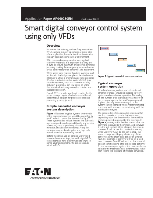
Smart digital conveyor control system using only VFDsOverviewNo matter the industry, variable frequency drives (VFD) can help simplify operations at every stepof the application, from the initial implementation through troubleshooting in your environment. With cascaded conveyors often working 24/7to deliver materials, it is important that they arein-sync to ensure maximum efficiency and minimal jamming, making the emergency stop mechanism a vital safety feature for personnel and equipment. While some large material handling systems, such as those in thermal power plants, require human interface to utilize a programmable logic controller (PLC) or distributed control system (DCS), less complex systems, such as a conveyor moving dishes in a cafeteria, can rely solely on VFDsthat are wired and programmed to conduct the cascaded operation.Overall, VFDs provide significant benefits for the entire conveyor system and offer a reliable and cost-effective solution for process control and protecting your equipment.Simple cascaded conveyor system descriptionFigure 1 illustrates a typical system, where eachof the cascaded conveyors would be controlled by an AC induction motor that is controlled by a VFD. These systems also include features like pull-cords and zero-speed switches in addition to any number of sensors, such as proximity, photoelectric, inductive, and vibration monitoring. Along the conveyor system, diverter gates and flaps help ensure materials are correctly routed.Before the digital age, all sensors were wiredto control contactor logic, but with digital VFDs, the sensors are now directly wired to VFDs. In some advanced systems, the sensors can be wired to PLCs.Figure 1. T ypical cascaded conveyor system Typical conveyorsystem operationAll safety features, such as the pull-cords and emergency stops, should be checked to verify system readiness before operation. Depending on the number of sensors and overall fidelity of the conveyor system, the start/stop commandis given manually to each conveyor, or the system can be operated with a master start/stop command with sensors communicating with the individual conveyors.The process logic for a cascaded system is that the first conveyor to start is the last to stop, depending upon the direction that the materials are being moved as guided by the diverters. In Figure 1, conveyor A is the first to start after the command is issued to the system, and conveyor E is the last to start. When stopping the system, conveyor E will be the first to cease operation, while Conveyor A will be the last to stop. The same concept would apply should any of the conveyors in the chain trip a sensor or a motor fault. For example, if conveyor C trips on a fault, then conveyors D and E will stop so that material doesn’t continue piling onto the stopped conveyor C. In a more complex system, the user can choose to divert the materials onto a different path, rather than forcing the stoppage of multiple conveyors.2Application Paper AP040230ENEffective April 2022Smart digital conveyor control systemusing only VFDsEATON Understanding sensor integrationThe most common sensor used in conveyor systems is a zero-speed switch, which provides feedback as to whether the conveyor is moving or has stopped. While an AC induction motor could be moving because VFDs are putting out voltage, the conveyor could actually be stopped. In that case, the zero-speed switch senses the actual movement—or lack thereof—coming from the conveyor belt. In Figure 1, if the zero-speed switch on conveyor C triggers, then the motors on conveyors C, D, and E will stop to prevent materials from piling up and accidental damage.It is important with the implementation of a zero-speed switch in the controls to begin sensing after the conveyor has started running at a certain frequency, but not before the conveyor has started moving. If the zero-speed switch begins sensing before the conveyor is running, then it will never start.When VFDs were less advanced, PLCs were a must for implementing control of a cascaded conveyor system, and before PLCs, hardware-wired relay controls were used. With advancements in the applications offered by VFD digital controls, most of the control functions required by the simple conveyor system (Figure 1) can be achieved by integrating the sensors to, and in the wiring between, the VFDs. Using only VFDs, rather than integrating PLCs with them, is a more cost-effective solution for achieving the same performance.How to integrate a conveyor system digitally with VFDsFor the following section, refer to Figure 1.Start command: A total of five VFDs—one for each conveyor motor—are connected on the control board. Run feedback from conveyor A is wired to conveyor B, and conveyor B is wired to conveyor C, and so on until all conveyors are connected to one another. The start command is issued to conveyor A, and the run feedback starts conveyor B, while conveyor B starts conveyor C, and onward until conveyor E begins moving. This is how VFD controls start all five conveyors.Conveying speed reference control: The main system speed reference input is only fed to conveyor A ’s VFD. Then, all five of the conveyor’s VFDs feed the speed control signal, i.e., A > B > C > D > E. Changing the speed reference to conveyor A subsequently changes the speed of the conveyors upstream that feed material to conveyor A.Stop/fault command: Just like the start command, the stop/fault command works via the five VFDs connected to one another on the control board. When the stop command is issued, conveyor E will be the first to stop, which is wired to then pass the command to conveyor D, and onward through the cascaded conveyors, i.e., E > D > C > B > A. Each conveyor is wired to the next in the chain, which is how the VFD stops all five conveyors. The faultcommand follows the exact same sequence as the stop command.Sensor interface: Users add more sensors to the conveyor system as fidelity increases. The zero-speed switch for each conveyor is wired to its specific external fault, and if triggered, the VFD will issue a fault to automatically stop the subsequent VFDs in the chain. The zero-speed switch can be bypassed by using drive-relay before the drive is running by setting the drive frequency above that of the moving conveyor. Once the relay picks up the preset speed frequency, it arms the zero-speed input on the same channel as the relay for initial bypass of zero-speed sensing. Simple control is achieved by using VFD digital controls without the need for a PLC.The pull-cords of the conveyors can be wired in series to the STO of the drives. This is the safest way to put an emergency stop on the drives running the motor and is possible to achieve with only VFDs.Figure 2. T ypical relay wiring for zero-speed sensingProximity sensors: Proximity sensors can be connected to the VFDs for a more intelligent start/stop by sensing the materials on the conveyor. Instead of running the systems continuously, it can be started and stopped based on the load that is traveling on the conveyor. This power-saving option enables the VFD to give a start command to the next conveyor in the cascade, only in the event it needs to be activated.Referring again to Figure 1, the proximity sensor would detect a load on conveyor E, and as soon as the load reaches a preset point, it would give a start command to conveyor D and so on until it reaches conveyor A.The same logic applies to the stoppage of conveyors. If the load falls below a certain preset threshold, it triggers a command to the rest of the conveyor system that a load isn’t being transported, thus turning it off to save power.Maintenance management: Sensors with vibration monitoring capabilities can be wired directly to the VFD to trigger a warning and generate a fault command to prevent damage to the system.Use of DM1 for a conveyor applicationSelection of DM1 modelBased on motor current selected for the conveyor, the user can select the DM1 model that supports 150% of the overload. DM1 is available in models capable of 110% or 150% overload for 60 seconds, but the conveyor application requires constant torque. Because of that, the 150% overload model (also known as an IH model) is recommended.In certain applications, the drive is required to deliver 200% overload, and the DM1 can deliver at that level for 2 seconds, every 20 seconds. After delivering the required torque in the overloaded zone, the drive will safely trip if the load demands higher torque for an extended period of time.Power and control wiring of DM1The DM1 installation manual will help determine recommended fuse protection and cable sizes, based on frame size and model. The manual also contains recommendations for grounding, EMC, brake resistor, and control wiring. Users should follow the design guidelines from the manual.Figure 3 shows typical control wiring for the DM1.3Application Paper AP040230ENEffective April 2022Smart digital conveyor control system using only VFDs EATON Figure 3. T ypical control wiring schemePlanning fieldbus control for the conveyorAs illustrated above, the control can be wired to the drive. If the conveyor system has a PLC, the DM1 Pro model offers onboard EtherNet/IP connection or, as an option, a Profibus T card forcontrolling and reading drive data via fieldbus link. The Modbus T RTU is available with every model.Eaton has developed Add-On Instructions (AOIs) for Rockwell PLC that support various assemblies, allowing for simple import to the Rockwell Studio5000, and used in PLC programming for controlling start/stop and speed reference to the DM1 drive. AOI also supports the data read from the PLC. For protocols and application notes to support PLC code implementation, refer to the quick start guide.DM1 software features for controlling conveyors Motor controlMotor control mode: The conveyor application can be run using V/F scalar control or Sensorless Vector Control (SVC). In V/F control mode, DM1 can offer +/–0.5% of base speed across a 30:1 speed range. If the speed reference to the conveyor is changing frequently, SVC control is recommended, which will provide +/–0.5% speed accuracy across a 60:1 speed range for the application.Speed reference: DM1 offers fixed speed reference throughdigital inputs that can be preset for speed reference, or the speed references can be an analog input or Fieldbus control register. DM1 offers various speed acceleration and deceleration profiles built into the drive control algorithms that can be selected by the user to minimize the equipment wear and tear.Start/stop mode: Ramp start/stop applications are typically used for conveyors, but DM1 also offers flying-start if required.Because particular conveyor applications might require a fast start/stop, the minimum programmable deceleration rate offered by DM1 is one-tenth of a second (0.1), but due to load inertia, actual stop time will vary.If the user desires a faster ramp rate than one-tenth of a second (0.1), the user can change the P1.2 setting. The user should make sure the speed reference is tethered to the motor design nominal speed, even though the P1.2 is set higher.For example, P 1.4 = 0.1 sec, P1.1 = 0, and P1.2 = 60 Hz If the drive is running at 40 Hz, then it will take(0.1/60) x 40 = 0.07 sec to drop to 0 Hz and 0.1 sec if the VFD was running at 60 Hz.Then, P 1.4 = 0.1 sec, P1.1 = 0, and P1.2 = 400 Hz The same thing changes if 40 Hz, then it will take(0.1/400) x 40 = 0.01 sec to drop to 0 Hz and 0.015 sec if the VFD was running at 60 Hz.For applications requiring multiple rapid starts/stops, an external dynamic braking resistor (DBR) should be considered, based on application duty cycle and the drive rating recommended in the catalog.Using an overvoltage (OV) regulator in the conveyor application to control the DC bus overvoltage is not recommended, as powermust be rapidly drained from the DC bus to achieve the fastest stop. When using the brake-chopper for external DBR, the user should disable the OV regulator in DM1.DC braking: Along with an external DBR, users can stop the conveyor via DC or flux brakes built into the DM1 drive. Because of the various field variables, it is recommended that brakingperformance is type-tested to determine the required performance.Application notes are available to support DC brake setup.Eaton1000 Eaton Boulevard Cleveland, OH 44122 United States © 2022 EatonAll Rights ReservedPrinted in USAPublication No. AP040230EN / Z26202 April 2022Eaton is a registered trademark.All other trademarks are propertyof their respective owners.Smart digital conveyor control systemusing only VFDsApplication Paper AP040230EN Effective April 2022Application controlIn addition to the standard start/stop control of the DM1, all models have a built-in PI controller for drive speed based on the process-control feedback.The PI controller is available for both inverted and non-inverted actions, and should be selected by the user based on the process. The DM1 Pro model offers more applications than the standard DM1 model.For a model comparison, reference the DM1 application manual. ProtectionsDM1 is a smart digital drive, offering protections to the drive itself, connected motor, and communications interface.Protections include—but are not limited to—motor thermal protection, input phase fault, external interlock fault, undervoltage and overvoltage, and loss of PI feedback.Additionally, the drive supports automatic restarts for certain faults, with the user selecting how many times the drive may restart during a predetermined period.T able 1. Built-in protection featuresDescriptionOvervoltage protection YesOvervoltage trip limit240 V drives: 430 V / 480 V drives: 850 V Undervoltage protection YesUndervoltage trip limit240 V drives: 210 V / 480 V drives: 390 V Earth fault protection YesInput phase supervision YesMotor phase supervision YesOvercurrent protection YesUnit overtemperature protection YesMotor overload protection YesMotor stall protection YesMotor underload protection YesDC bus overvoltage control Yes STO protectionDM1 offers SIL2-certified, built-in Safe Torque Off (STO). STO prevents an unexpected start of the motor, and therefore, stops the drive from producing power/torque to the load. This feature is particularly useful for maintenance and personnel protection.The STO trigger is a stop command to the drive, forcing the motor to coast to a stop. This function is initiated through the hardware circuit rather than the software, disabling the output IGBTs by either disconnecting the power supply to the gate control driver IC (STO1) or disabling the output of the gate control driver IC (STO2).The gate-drive output signals control the IGBT module, andwhen they are disabled, the drive will not generate torque in the motor shaft.More detailed application notes for STO wiring configurationsare available.Figure 4. STO wiring scheme for DM1 using dry contacts。
格兰富水泵自带变频器操作说明书 R100操作
13
13
13
13
14 有关安装详情,请参见标准水泵的安装与使用说明
15
15
16
16
16
16
16
16
16
16
17
17
2.1 电气连接—单相泵 注:用户或者安装人员要保证水泵得以按照现行有效的国际和当 地标准安装正确的接地和保护,所有工作必须由有资格的电气人 员来进行。
实际的电源电路连接参见图 3
图3
综述 双头泵 安装 电气连接—单相泵 电源开关 触电保护—间接触点 附加保护 马达保护 过电压保护 供电电压 泵的启动/停止 电气连接—三相泵 电源开关 触电保护—间接触点 附加保护 马达保护 过电压保护 电源电压 泵的启动/停止 其它连接 信号电缆 泵的设定 工厂设定 通过控制面板进行设定 设定值设定 设定为最大工作曲线 设定为最小工作曲线 泵的启动/停止 通过 R100 进行设定 运行菜单 设定值的设定 运行模式设定 故障指示 警报记录 状态菜单 实际设定值显示 运行模式显示 实际值显示 实际速度显示 输入功率和功耗显示 运行时间显示 安装菜单 选择控制模式 控制器的设定 选定外部设定值信号 选择故障、运行和待命信号继电器 锁定水泵上的按钮 水泵编码 选择数字输入功能 传感器设定 设定最小和最大工作曲线 外部强制控制信号 启动/停止输入 数字输入 外部设定值信号 总线信号 设定的优先级 指示灯和信号继电器 绝缘测量 技术数据—单相泵 电源电压 漏电电流 输入/输出 技术数据—三相泵 电源电压 漏电电流 输入/输出 其它技术数据 废物处理
2.1.3 附加保护 如果水泵所连接的电力系统带有附加的对地漏电断路器保
护,则该断路器必须用以下符号进行标记。
2.1.7 泵的启动/停止 由电源执行的启动和停止次数每小时不得超过 4 次。 如果需要更多的启动和停止次数,则启动/停止水泵时,需
水泵变频器的使用方法及参数调整

水泵变频器的使用方法及参数调整1. 水泵变频器的介绍水泵变频器是一种用于控制水泵运行速度的设备,通过调节电压和频率来实现水泵的启停、运行速度调整等功能。
在工业生产、农业灌溉、建筑工程等领域中广泛应用。
2. 水泵变频器的使用方法•安装及连接电源:首先确保水泵变频器与电源连接正确,接线牢固,各接口无松动。
•设置相关参数:根据实际情况设置水泵变频器的相关参数,包括输入输出电压、额定频率、最大输出频率等。
•手动控制:在手动模式下,可通过控制面板手动调整水泵的启停、运行频率等操作。
•自动控制:在自动模式下,可通过外部传感器或控制系统实现对水泵的自动控制,根据需求调整频率和运行状态。
•故障诊断:当水泵变频器出现故障时,及时进行故障诊断,找出原因并进行修复,确保设备正常运行。
3. 水泵变频器参数调整•输出频率设置:根据水泵的实际需求设置输出频率,一般情况下应根据水泵的额定频率来调整。
•最大输出频率:设定水泵变频器的最大输出频率,一般情况下应考虑到水泵本身的最大工作频率限制。
•输出电压限制:设定水泵变频器的输出电压限制,保证在合理范围内运行,避免损坏水泵。
•过载保护参数:设置水泵变频器的过载保护参数,当水泵超载时能及时停止运行,避免损坏设备。
•其他参数:根据具体情况调整相关参数,如加速时间、减速时间、启动方式等,以确保水泵正常运行。
4. 注意事项•安全操作:在设置参数和调整过程中,务必确保安全操作,避免发生意外事故。
•定期维护:定期检查水泵变频器的运行情况,保持设备清洁,及时处理故障,延长设备寿命。
•合理使用:根据实际需求合理使用水泵变频器,避免长时间超负荷运行,确保设备稳定运行。
通过以上方法和参数调整,可以更好地使用水泵变频器,提高水泵的工作效率,延长设备使用寿命。
希望以上内容对您有所帮助,谢谢阅读。
JTE388智能恒压供水变频器用户手册

JTE388 series智能恒压供水变频器用户手册第一章安全信息及注意事项●严禁用潮湿的手进行作业。
●严禁在电源没有完全断开的情况下进行配线作业。
●智能恒压机在通电运行过程中,请勿打开面盖或进行配线作业,否则有触电的危险。
●实施配线、检查等作业时,须在关闭电源10分钟后进行,否则有触电的危险。
●在运行状态下停电再上电, 智能恒压机会自动启动,请在上电之前确保使用安全,否则有可能造成人身伤亡事故。
●请勿安装使用元件损坏或缺失的智能恒压机,以防发生人身意外及财产损失。
●主回路端子与电缆必须牢固连接,否则因接触不良可能造成智能恒压机的损坏。
●确保将智能恒压机安装在防火材料上(如金属),以防失火。
●确保无异物进入智能恒压机,如电线碎片、焊锡、锌铁片等,以防电路短接导致智能恒压机烧毁。
●在智能恒压机的输入电源侧,请务必配置电路保护用的无熔丝断路器或带漏电保护的断路器,以防止因智能恒压机故障而引起的事故扩大化。
●实施配线、检查等作业时,须在关闭电源10分钟后进行,否则有触电的危险。
●长时间不使用的智能恒压机请务必将输入电源切断,以免因异物进入或其它原因导致智能恒压机损坏,甚至引起火灾。
●由于智能恒压机的输出电压是PWM脉冲波,因此在其输出端请不要安装电容或浪涌电流吸收器(如压敏电阻),否则将会导致智能恒压机出现故障跳闸,甚至功率元器件的损坏。
如已有安装的,请务必拆除。
第二章外围电气元件及连接1)不要在恒压机的输出侧安装电容器或浪涌抑制器,这将导致恒压机的故障或电容和浪涌抑制器的损坏。
2)恒压机的输入/输出(主回路)包含有谐波成分,可能干扰恒压机附件的通讯设备。
因此,安装抗干扰滤波器,使干扰降到最少。
3)本系列恒压机虽内装有雷击过流保护装置,对于感应雷有一定的自我保护能力,但对于雷电频发处客户还应在恒压机前端加装防雷保护装置。
4)在海拔高度超过1000m的地区,由于空气稀薄造成恒压机的散热效果变差有必要降额使用。
- 1、下载文档前请自行甄别文档内容的完整性,平台不提供额外的编辑、内容补充、找答案等附加服务。
- 2、"仅部分预览"的文档,不可在线预览部分如存在完整性等问题,可反馈申请退款(可完整预览的文档不适用该条件!)。
- 3、如文档侵犯您的权益,请联系客服反馈,我们会尽快为您处理(人工客服工作时间:9:00-18:30)。
用户手册前言感谢您选用8100智能水泵变频器,本说明书为您提供相关的操作说明及参数的详细解释,安装、运行、维护或检查之前,敬请认真阅读本说明书。
使用前,务必确认接线是否正确以及水泵的转向是否正确。
目录第一章操作面板说明 (06)1.1操作面板示意图 (06)1.2指示灯说明 (06)1.3按键操作说明 (07)1.4压力设置说明 (08)第二章型号、外观及接线 (09)2.1型号说明 (09)2.2外形尺寸和安装尺寸 (09)2.3主电路与控制端子接线图 (15)2.4传感器接线图 (16)2.5端子标识及说明 (17)第三章快速调试 (19)第四章8100参数表 (22)4.1运行状态面板显示参数 (22)4.2停机状态面板显示参数 (22)4.3单机常用参数组 (23)4.4多泵联机常用参数组 (25)4.5调试参数组 (26)4.6PID及休眠参数组 (27)4.7水泵保护参数组 (29)4.8电机参数组 (30)4.9保护和故障参数组 (31)4.10端子参数组 (33)4.11通讯参数组 (34)4.12监控参数组 (35)4.13代理商参数组 (36)4.14厂家参数组 (36)4.15部分参数详细说明 (37)第五章故障信息及排除方法 (45)5.1故障代码详述 (45)5.2常见故障及其处理方法 (48)第六章通讯协议 (50)6.1命令码及通讯数据描述 (50)第七章典型应用案例 (54)7.1单泵控制案例1 (54)7.2单泵控制案例2 (55)7.3多泵控制案例 (57)7.4多联机通讯协议 (57)7.5一拖二控制案例 (58)安全注意事项危险:表示可能会导致死亡或严重人身伤害的状况。
注意:表示可能会导致人身中等程度的伤害或轻伤,以及发生设备损坏的状况。
同时,该标志也用于表示错误或不安全使用的注意事项。
■到货检查◎若变频器损坏或者零件缺失,则不可安装或运行。
否则可能会导致设备损坏或人身伤害。
■安装◎安装、移动时请托住产品底部,不能只拿住外壳,以防砸伤或摔坏变频器。
◎变频器要远离易燃易爆物体,远离热源,并安装于金属等阻燃物上。
◎变频器安装在电柜或其他封闭物中时,要在柜内安装风扇或其他冷却设备、设置通风口以确保环境温度低于40℃,否则可能因为环境温度过高而损坏变频器。
■接线◎接线必须由合格的专业电气工程人员完成,否则有可能触电或导致变频器损坏。
◎确定电源处于断开状态时再开始接线,否则可能导致触电或发生火灾。
◎接地端子要可靠接地,否则变频器外壳有带电的危险。
◎请勿触摸主回路端子,变频器主回路端子接线不要与外壳接触,否则可能导致触电。
◎制动电阻的连接端子是(+)、PB,请勿连接除此以外的端子,否则可能导致火灾。
◎接线前确认变频器额定电压、相数和输入电源电压、相数相符合,否则可能导致火灾或人身伤害。
◎交流输入电源不能接到变频器输出端子U、V、W上,否则将导致变频器损坏并且不能享受保修服务。
◎不能对变频器进行耐压测试,否则将导致变频器损坏。
◎变频器的主回路端子配线和控制回路配线应分开布线或垂直交叉,否则将会使控制信号受干扰。
◎主回路端子的接线电缆应使用带有绝缘套管的线鼻。
◎当变频器和电机之间的电缆长度超过50米时,建议使用输出电抗器以保护变频器和电机。
■运行◎变频器接线完成并加上盖板后方可通电,严禁带电时拆卸盖板,否则可能导致触电。
◎当对变频器设置了故障自动复位或停电后自动重启功能时,应预先对设备系统采取安全保护措施,否则可能导致人员伤害。
◎“STOP/RESET”(停止/复位)按键可能因某功能设置而失效,可在变频器控制系统中安装一个独立的应急断电开关,否则可能导致人员伤害。
◎变频器通电后,即使处于停机状态,变频器的端子仍带电,不可触摸,否则有触电危险。
◎不要采用断路器来控制变频器的停止、启动,否则可能导致变频器损坏。
◎因变频器使运行速度从低到高的时间极短,所以在运行前请确认电机和机械设备处于允许的使用范围内,否则可能导致设备损坏。
◎散热器和制动电阻温度较高,请勿触摸,否则可能引致烫伤。
◎变频器出厂时预设的参数已能满足绝大部分设备运行要求,若非必要,请勿随意修改变频器参数。
即使某些设备有特殊需求,也只能修改其中必要的参数。
否则,随意修改参数可能引致设备损坏。
■维护和检查◎通电时请勿触摸变频器的端子,否则可能引致触电。
◎请指定合格的电气工程人员进行维护、检查或更换部件等工作。
◎断电后至少等待10分钟或者确定没有残余电压后才能进行维护和检查,否则可能引致人员伤害。
◎PCB板上有CMOS集成电路,请勿用手触摸,否则静电可能损坏PCB板。
■其它◎严禁私自改造变频器,否则可能引致人员伤亡。
擅自更改后的变频器将不再享受保修服务。
第一章操作面板说明1.1操作面板示意图(1)菜单:从固定模式转到参数模式时使用。
(2)压力/设定:设定水压快捷键以及设定参数时的确定键。
(3)移位:切换显示内容以及修改参数时移动光标用。
运行状态下按“移位”键可在运行频率、输出电流、设定压力以及反馈压力之间来回切,修改参数时,按“移位”键,闪烁位为当前可修改位。
(4)▲▼键:用于设定参数值和设定压力值的修改。
(5)运行:启动方式为键盘时的启动按钮。
(6)停止/复位:启动方式为键盘时的停止按钮和故障复位按钮。
(7)停机时参数监控状态下按“移位”键5秒以上,F0、F1组参数可恢复出厂设置,当屏幕显示的提示字母“End”结束后,表示恢复出厂设置完成。
1.2指示灯说明◆运行:(常亮):运行指示;(闪烁):休眠停机指示。
◆停止:停机指示(待机指示)。
◆报警1:控制器故障报警。
◆报警2:管网水压异常报警。
1.3按键操作说明三级菜单分别为:①功能码组号(一级菜单)②功能码标号(二级菜单)③功能码设定值(三级菜单)说明:在三级菜单操作时,可按“菜单”或“压力/设定”返回二级菜单。
两者的区别是:按“压力/设定”将设定参数存入控制板,然后再返回二级菜单,并自动转移到下一个功能码标号;按“菜单”则直接返回二级菜单,不存储参数,保持并停留在当前功能标号。
在三级菜单状态下,如参数没有闪烁,表示该位不可修改,可按“移位”键切换闪烁位;注:参数表中标注“●”的参数,请在停机状态下修改,标注“◎”的参数为实际检测记录值,不能更改。
举例:将F0.02从0改为1,长按菜单键2秒可进入参数组。
1.4压力设置说明附:压力换算关系式:0.1MPa(兆帕)=100KPa(千帕)=1Bar(巴)=1Kgf/cm2(公斤力/平方厘米)第二章型号、外观及接线2.1型号说明2.2外形尺寸和安装尺寸0.75~2.2KW外型尺寸及安装尺寸示意图4KW~7.5KW外型尺寸及安装示意图11kW~18.5kW外型尺寸及安装尺寸示意图22kW~37kW外型尺寸及安装尺寸示意图45kW~55kW外型尺寸及安装尺寸示意图75kW~110kW外型尺寸及安装尺寸示意图132kW~185kW外型尺寸及安装尺寸示意图200kW~250kW外型尺寸及安装尺寸示意图280kW~400kW外型尺寸及安装尺寸示意图2.2.1外引键盘的外形尺寸0.75kW~2.2kW外引键盘的外形尺寸4kW~7.5kW外引键盘的外形尺寸11kW ~400kW 外引键盘的外形尺寸2.2.2外引键盘的托盘尺寸11kW ~400kW 外引键盘的外形尺寸2.3主电路与控制端子接线图注意事项:1、端子:◎表示主回路端子:○表示控制回路端子。
2、选择的控制器电压为220V时,接端子R、T即可。
3、0.75~2.2kW没有M5和M6。
2.4传感器接线(1)端子说明◆10V/24V---远传压力表/压力变送器电源接线端◆AVI---0~10V模拟信号输入端◆ACI---4~20mA信号输入端◆GND---10V电源信号地◆COM---24V电源信号地(2)接线图本控制器可接远传压力表和压力变送器两类反馈器件,请根据反馈器件配合下列各图接线。
①远传压力表:工作电压10VDC,输出0~10VDC,接线方式如下图所示②24V压力变送器:工作电压范围10~30V,输出4~20mA,特别注意2.2KW及以下功率段无24V端子。
二线制压力变送器接线图三线制压力变送器接线图③10V压力变送器:工作电压范围10DC,输出4~20mA三线制压力变送器接线图2.5控制端子标识及说明(1)控制端子[0.75kW-2.2kW(G)]控制端子:TA TB TC M1M2M3M424V COM GND FM AM ACI10V AVI GND MCM MO1 [4kW~400kW(G)]控制端子:(2)控制回路端子功能说明(3)控制回路端子接线说明请使用多芯屏蔽电缆或双绞线连接控制端子。