G040-123伺服阀检测仪说明书
流量检测仪使用说明书

Flo-Tech, PFM6 流量压力检测仪使用说明书流量压力检测仪的使用要领1. 检测仪各部名称(图1)涡轮流量计各部名称(图2)2. Flo-tech检测仪参数* 为现用检测仪(1) 检测仪使用要点本检测仪操作简单,不需要特殊练习,就可以立刻使用。
为了正确的判断试验结果,有必要事先了解测试对象的液压系统和各液压执行部件,掌握必要的资料,比如:操作压力、流量、溢流阀设定压力、液压泵的最高输出压力、液压泵的性能曲线等。
①液压软管的连接检测仪如上表所示有三种机型,其软管的连接分两种类型a、PFM6-50、PFM6-85为1英寸的PT内螺纹。
b、PFM6-200上附有1英寸PT螺纹的连接器。
90°的管接头、T型管接头、阀等距离检测仪的输入端最好在30cm以上,因为这些部件将会给流体的测量带来误差。
软管的另一侧(与被测机器连接侧)通常与连接检测仪一侧为相同连接螺母,所以当管径或螺纹不同时,请利用转接器。
②操作要领检测仪的操作是简单的,但误操作将会给检测仪或被测试机器、回路带来不良影响。
使用者在使用前请读熟本使用说明书,避免误操作,以提高测试效率。
a、转换开关通常在中央位置(OFF)测试流量时请放在(FLOW)档位测试油温时请放在(TEMP)档位测试结束后,请勿必将开关拨回到OFF位置。
干电池使用过期电压下降时,仪表(流量、温度计上的冒号:)将发生闪烁。
此时,请更换干电池。
b、认真确认软管是否已正确无误地连接在检测仪的输入、输出端。
检测仪可以并列接入高压侧,但流向若是接反则不能测量正确的流量。
c、液压回路动作前,应将加载阀反时针方向旋转打开。
d、加载阀可以用手简单地进行操作,在加压和卸压时,请缓慢地进行操作。
e、液压回路动作停止之前,要将加载阀打开,确认压力是否已降到零。
在进行多项压力测试时,每一次测试结束,也都应该将加载阀先打开,然后进行下一个项目的测试。
f、安全圆片是保护检测仪和液压机器的,测试时,请密切注意压力表的读数,使之不要超过回路的最高压力。
Omega 流量监测仪产品文档说明书
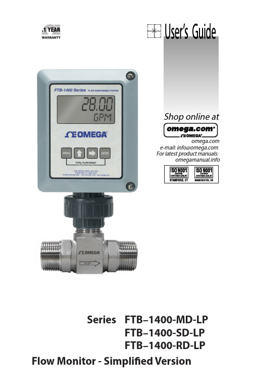
e-mail:**************For latest product manuals:Shop online atSeries FTB–1400-MD-LP FTB–1400-SD-LP FTB–1400-RD-LPFlow Monitor - Simplified VersionServicing North America:Servicing Europe:U.S.A.:Omega Engineering, Inc., One Omega Drive, P.O. Box 4047ISO 9001 Certified Stamford, CT 06907-0047Toll-Free: 1-800-826-6342Tel: (203) 359-1660FAX: (203) 359-7700e-mail:**************Canada:976 BergarLaval (Quebec), Canada H7L 5A1Toll-Free: 1-800-826-6342TEL: (514) 856-6928FAX: (514) 856-6886e-mail:*************For immediate technical or application assistance:U.S.A. and Canada:Sales Service: 1-800-826-6342/1-800-TC-OMEGA ®Customer Service: 1-800-622-2378/1-800-622-BEST ®Engineering Service: 1-800-872-9436/1-800-USA-WHEN ®Mexico:En Español: 001 (203) 359-7803FAX: (001) 203-359-7807**************.mxe-mail:*****************Benelux:Managed by the United Kingdom Office Toll-Free: 0800 099 3344TEL: +31 20 347 21 21FAX: +31 20 643 46 43e-mail:**************Czech Republic:Frystatska 184733 01 Karviná, Czech RepublicToll-Free: 0800-1-66342TEL: +420-59-6311899FAX: +420-59-6311114e-mail:*****************France:Managed by the United Kingdom OfficeToll-Free: 0800 466 342TEL: +33 (0) 161 37 29 00FAX: +33 (0) 130 57 54 27e-mail:**************Germany/Austria:Daimlerstrasse 26D-75392 Deckenpfronn, GermanyToll-Free************TEL: +49 (0) 7059 9398-0FAX: +49 (0) 7056 9398-29e-mail:*************United Kingdom:OMEGA Engineering Ltd.ISO 9001 Certified One Omega Drive, River Bend Technology Centre, NorthbankIrlam, Manchester M44 5BD EnglandToll-Free: 0800-488-488TEL: +44 (0)161 777-6611FAX: +44 (0)161 777-6622e-mail:**************.uk OMEGAnet ® Online Service Internet e-mail **************It is the policy of OMEGA Engineering, Inc. to comply with all worldwide safety and EMC/EMI regulations that apply. OMEGA is constantly pursuing certification of its products to the European New Approach Directives. OMEGA will add the CE mark to every appropriate device upon certification.The information contained in this document is believed to be correct, but OMEGA accepts no liability for any errors it contains, and reserves the right to alter specifications without notice.WARNING: These products are not designed for use in, and should not be used for, human applications.CONTENTSINTRODUCTION . . . . . . . . . . . . . . . . . . . . . . . . . . . . . . . . . . . . . . . . . . . . . . . . . . . . . . . . . . .4 SPECIFICATIONS . . . . . . . . . . . . . . . . . . . . . . . . . . . . . . . . . . . . . . . . . . . . . . . . . . . . . . . . . .6 OPERATING THE MONITOR . . . . . . . . . . . . . . . . . . . . . . . . . . . . . . . . . . . . . . . . . . . . . . . .7 BASIC PROGRAMMING MODE . . . . . . . . . . . . . . . . . . . . . . . . . . . . . . . . . . . . . . . . .7 PROGRAMMING . . . . . . . . . . . . . . . . . . . . . . . . . . . . . . . . . . . . . . . . . . . . . . . . . . . . . . .7 FTB–1400 Simplified 4-20 mA Programming . . . . . . . . . . . . . . . . . . . . . . . . .10 ADDITIONAL INPUT OPTIONS . . . . . . . . . . . . . . . . . . . . . . . . . . . . . . . . . . . . . . . . . . .12 TROUBLESHOOTING GUIDE . . . . . . . . . . . . . . . . . . . . . . . . . . . . . . . . . . . . . . . . . . . . .17 DEFAULT K-FACTOR VALUES . . . . . . . . . . . . . . . . . . . . . . . . . . . . . . . . . . . . . . . . . . . . .17 PART NUMBERING . . . . . . . . . . . . . . . . . . . . . . . . . . . . . . . . . . . . . . . . . . . . . . . . . . . . . .18 REPLACEMENT PARTS . . . . . . . . . . . . . . . . . . . . . . . . . . . . . . . . . . . . . . . . . . . . . . . . . . .183INTRODUCTIONThe FTB–1400 Flow Monitor is a state-of-the-art, digital signal processing flow monitor, designed to provide the user with exceptional flexibility at a very affordable price . Though designed for use with Omega FTB–1400 flow meters, this display can be used with almost any flow meter producing a low amplitude AC output or contact closure signal(s) .This flow monitor is capable of accepting a low-level frequency input for calculating flow rate and total . These calculations can then be displayed in the desired units of measurement . All FTB–1400 flow monitors come pre-calibrated, from the factory, if ordered with an Omega FTB–1400 Flow Meter . If required, however, it can easily be re-configured in the field . The monitor’s large 8 digit by .75" numeric liquid crystal display makes extend-ed range viewing practical . The second 8 digit by .38" alphanumeric display provides for selectable units viewing in run mode and prompts for vari-ables in program mode . Finally, the user can choose between displaying rate, total, or alternating between both rate and total .Figure 1: Flow Monitor Face4FEATURES• Displays Rate and/or Total• Large 0 .75 Inch, 8 Digit Display for Easy Viewing• Simple, Front Panel Programming• Various Mounting Styles Available• NEMA 4X Suitable for Outdoor Mounting• Intrinsically Safe• Microprocessor Based, Low Power Components• 4-20 mA Loop Powered• Automatic Decimal Point Locating• Lead Zero Blinking• Surface Mount Technology Use Throughout5SPECIFICATIONSPower Supply:4-20 mA loop powerPower Consumption:25 mA (maximum)Alphanumeric Rate and Total Display:8 digit, .75" high numeric display8 character, .38" high alphanumeric displayFixed or toggle modes of operation for flow rate and totalizer display Pulsed Output Signal:Outputs one pulse for each increment of the least significanttotalizer digitMax . Voltage: 30 VdcPulse Type: Opto-Isolated open collector transistorPulseWidthONState:***************************** Magnetic Pick-up Inputs:Frequency Range: 0 to 3500 HzTrigger Sensitivity: 30 mV p-pOver Voltage Protected: ±30 VDCFrequency Measurement Accuracy: ±0 .1%Temperature Drift: 50 ppm / ºC (max)Transient Overvoltages: Category 3, in accordance with IEC664 Pollution Degree: 2, in accordance with IEC664Mounting Classification:Meter Mount: NEMA 4X EnclosureRemote Mount: NEMA 4X EnclosureSwivel Mount: NEMA 4X EnclosureEnvironmental:Operating Temperature: -22 ºF to +158 ºF (-30 ºC to +70 ºC)Humidity: 0-90% Non-condensingUnits of Measure:Gallons, Oil Barrels, Liters, Cubic Meters, MGal, Cubic FT, MCF, MMCF Megltrs, Acre FT, Liq . Barrels, LBS, KGSTime Intervals: Day, Hour, Minute, Second6OPERATING THE MONITORThe monitor has two modes of operation referred to as the RUN mode and the PROGRAM mode . Both the run mode and the program mode display screen enunciators confirming the state of the monitor . A quick glance at the lower left hand corner of the LCD screen will confirm operating status . Normal operation will be in the RUN mode . To access the program mode, press the MENU button until the first programming screen is displayed . After programming the display with the necessary information, a lock out feature can be turned on to prevent unauthorized access or changing the meter’s setup parameters .BASIC PROGRAMMING MODEKeys:MENU – Switch between RUN and PROGRAM modesUP Arrow – Scrolls through programming sub-menus in forwarddirection and increments numeric variablesRIGHT Arrow – Scrolls through programming sub-menus in reverse direction and moves the active digit to the rightENTER – Used to enter sub-menus, save programming informationand in the reset processIf your monitor was ordered with an Omega flow meter, the two compo-nents ship from the factory calibrated as a set . If the monitor is a replace-ment, the turbine’s K-factor has changed, or the monitor is being used with some other pulse generating device, programming will be necessary . PROGRAMMINGEach turbine flow meter is shipped with either a K-factor value or frequency data . If frequency data is provided, the data must be converted to a K-factor before programming . K-factor information, when supplied, can usually be found on the neck of the flow meter or stamped on the body . The K-factor represents the number of pulses per unit of volume . The K-factor will be needed to program the monitor .ENTER PRO GRAM MO DE – Change to program mode by press-ing the MENU button once . The mode indicator will change from RUN to PROGRAM .78ton once . The current meter size number will begin to flash . Using the arrow keys, scroll through the size choices until you find the bore size ofyour meter . Press ENTER once to save the meter size choice .Rate / Total DisplayAndProgrammingKeys Mode IndicatorAndProgramming ChoicesFigure 2: Flow Monitor ControlsENTER THE METER’S K-FACTOR UNIT – Directly after the METER size is selected, the display’s K-factor unit must be chosen . Use the UP arrow key to select your K-factor unit . For meters calibrated in gallons, use PUL/GAL (pulses per gallon); for meters calibrated in cubic meters, use PUL/M3 (pulses per cubic meter), etc . Press ENTER to save the K-factorunit and advance to the next parameter .SELECT THE RATE/TOTAL UNITS OF MEASURE – The monitor allows the choice of five common rate/total units . The monitor shows the rate/ total unit that the display is currently set for . If the current selection is correct, press the ENTER key once to advance to the next parameter . To change to an alternate unit, use the arrow keys to scroll to the desiredrate unit and press ENTER to save the choice .SELECT THE DISPLAY FUNCTION – The monitor can display RATE or TOTAL or alternate between BOTH rate and total . At the DISPLAY prompt, press the ENTER key once . The monitor now shows the display mode currently in effect . If the current selection is correct, press the ENTER key to advance to the next parameter . To change to an alternate display mode, use the ar-row keys to scroll to the desired display mode and press ENTER to save the choice .A TEST function is also available in the Display Function sub-menu . With the test function selected, the display acts like a frequency counter and displays the raw input frequency being supplied to the frequency input terminals . This is very useful when troubleshooting flow problems .9TOTALIZER PULSE OUTPUT – The pulse output parameter can be either enabled or disabled . When enabled this output generates 20 mS duration pulse for every time the least significant digit of the totalizer increments . The amplitude of the pulse is dependent on the voltage level of the supply connected to the pulse output and is limited to a maximum 30 VDC . FTB–1400 SIMPLIFIED 4-20 MA PROGRAMMINGFLOW 4mA SETTING – When the loop powered option is ordered, the flow rate that corresponds to 4mA must be set . Zero is default flow rate for this setting . If the current selection is correct, press the ENTER key once to advance to the next parameter . If adjustment is required, use the RIGHT arrow key to select the position of the number you wish to change . Then use the UP arrow key to increment the number . Once you have completed this step, press the ENTER key to advance to the next parameter .FLOW 20mA SETTING – The flow rate that corresponds to 20mA must be set next . The turbine meter’s maximum flow rate is the default value .If the current selection is correct, press the ENTER key once to advance to the next parameter . If adjustment is required, use the RIGHT arrow key to select the position of the number you wish to change . Then use the UP arrow key to increment the number . Once you have completed this step, press the ENTER key to advance to the next parameter .4-20mA CALIBRATIO N – When ordered with a 4-20mA option, this menu item allows the fine adjustment of the 4-20mA output . The 4mA setting is typically between 35 and 50 . To set the 4mA value, connect an ammeter in series with the loop power supply . At the 4mA OUT prompt, adjust the 4mA value to obtain a 4mA reading on the amme-ter . The UP arrow key increments the value and the RIGHT arrow key decrements the value . When a steady 4mA reading is obtained on the ammeter, press the ENTER key to lock in this value and move to the 20mA adjustment . The 20mA adjustment is performed using the same procedure as the 4mA adjustment .4-20mA TEST – The monitor contains a diagnostic routine that allows the simulation of mA values between 4 and 20 to check output track-ing . At the 4-20TEST prompt the arrow keys change the simulated mA output in increments of 1mA . The ammeter should track the simulated mA output . If a 4-20mA test in not necessary, pressing the ENTER key once will escape the testing at any time .1011Figure 3: Typical Ammeter ConnectionPASSWO RD – Password protection prevents unauthorized users fromchanging programming information . Initially, the password is set to all ze-ros . To change the password, simply enter any 4 digit code using the arrow keys as previously described to enter the password value . Pressing ENTER once will store the password and take you back to the RST PSWD screen .RST PSWD – The reset password screen allows the operator to enter any 4 digit code for the manual reset totals function .RESET TOTAL – To reset the monitor total display, in RUN mode press the MENU and ENTER simultaneously until TOTAL RST starts to flash . The TOTAL RST will stop flashing and the display will return to the RUN mode at the conclusion of the reset procedure .STORE TOTAL – The current total can be manually stored in the monitor’s flash memory . Press and hold the ENTER key for 2 seconds . The display will respond with a flashing TOTALSVD and then return to the RUN mode .AUTOMATIC STORE TOTAL – The monitor is equipped with a store total feature that works automatically, saving the current total to flash memory . The frequency of saves depends on the power supply option chosen .Loop Powered: Once every ten minutes . ADDITIONAL INPUT OPTIONSThe FTB–1400 Flow Monitor is capable of receiving magnetic pick-up input (small signal sine wave) or a contact closure input (pulse) . Since Omega FTB–1400 Flow Meters utilize a magnetic pick-up, the monitor is shipped configured for magnetic pick-up input . To change to a contact closure in-put, remove JP2 from the top two pins and jumper them to the bottom two pins . See Figure 4 .+10 - 30 VDC+1 - 5 VDCFigure 4: Wiring Diagram12Figure 5: Basic Programming Menu13REMOTE DISPLAY14151SWIVEL MOUNTFigure 6: MOUNTING OPTIONSFigure 7: Installation Drawing 16TROUBLESHOOTING GUIDEDEFAULT K-FACTOR VALUES17PART NUMBERINGFTB–1400–X D–LPMounting StyleM -Meter MountR -Remote MountS -Swivel MountREPLACEMENT PARTS18Where Do I Find Everything I Need for Process Measurement and Control?OMEGA…Of Course!Shop online at SMTEMPERATUREThermocouple, RTD & Thermistor Probes, Connectors, Panels & Assemblies Wire: Thermocouple, RTD & Thermistor Calibrators & Ice Point ReferencesRecorders, Controllers & Process Monitors Infrared PyrometersPRESSURE, STRAIN AND FORCETransducers & Strain Gages Load Cells & Pressure Gages Displacement Transducers Instrumentation & AccessoriesFLOW/LEVELRotameters, Gas Mass Flowmeters & Flow Computers Air Velocity IndicatorsTurbine/Paddlewheel Systems Totalizers & Batch ControllerspH/CONDUCTIVITYpH Electrodes, Testers & Accessories Benchtop/Laboratory MetersControllers, Calibrators, Simulators & Pumps Industrial pH & Conductivity EquipmentDATA ACQUISITIONData Acquisition & Engineering Software Communications-Based Acquisition Systems Plug-in Cards for Apple, IBM & Compatibles Datalogging System sRecorders, Printers & PlottersHEATERSHeating CableCartridge & Strip Heaters Immersion & Band Heaters Flexible Heaters Laboratory HeatersENVIRONMENTALMONITORING AND CONTROLMetering & Control Instrumentation Refractometers Pumps & TubingAir, Soil & Water MonitorsIndustrial Water & Wastewater TreatmentpH, Conductivity & Dissolved Oxygen InstrumentsM-5299/0613☑☑☑☑☑☑☑☑☑☑☑☑☑☑☑☑☑☑☑☑☑☑☑☑☑☑☑☑☑☑☑☑☑。
干法除尘切换站液压伺服系统使用说明书

中宝滨海镍铁干法除尘切换站液压伺服系统使用和维护说明书中国重型机械研究院中宝干法除尘切换站液压伺服系统使用和维护说明书中宝干法除尘液压切换伺服系统由液压站、液压阀台和配管组成,用于控制系统中放散杯阀及回收杯阀的动作。
共有2套液压伺服系统,控制功能完全相同,分为1#液压控制系统和2#液压控制系统。
下面以一套液压伺服系统的为例进行控制说明。
如果要区分各电气信号,则在相应的代号前加上1、2系统代号即可。
如代号为YV1则分别变为1YVO1、2YV01。
1.设备组成及性能参数1.1 主要性能参数油箱容积:0.5m3主泵装置:最大流量:60L/min 电机功率:22KW工作压力:15MPa转速:1500rpm蓄能器总容积:2X25L=50L循环泵流量:40L/min循环泵电机功率: 1.1KW循环过滤器:过滤精度5μm回油过滤器:过滤精度10μm压油过滤器:过滤精度10μm适用介质:美孚N46#抗磨液压油供油温度:45℃-55℃清洁度要求:NSA1638 7级1.2液压系统组成液压系统有液压站及液压阀台组成。
1.2.1 液压站主要由油箱装置、主泵装置、循环过滤冷却装置组成。
①油箱装置(1台)主要用于存储系统介质,并兼有散热、杂质沉淀等功能。
油箱为长方体结构,有效容积为0.5m3,采用不锈钢材料。
油箱装置带有3个2KW的电加热器(125-1¯3)。
为了适应系统自动化和可靠性方面的要求,油箱装置带有液位继电器(130)以对油箱液位进行自动监控报警;油箱装置带有液位继电器(130)以对油箱液位进行自动监控报警;油箱装置带有进口HYDAC的温度控制器(121)以对系统的加热、冷却发出控制信号。
油箱装置还带有液位计(123)、空气过滤器(103)和放油球阀(124)等。
油箱装置还装有主回油过滤器(114)1只,过滤精度10μm,过滤器堵塞可发讯报警。
②主泵装置(2台)主泵装置输出流量60L/min;压力15MP;22KW。
系列伺服阀和比例阀安全操作及保养规程
系列伺服阀和比例阀安全操作及保养规程1. 引言本文档旨在提供系列伺服阀和比例阀的安全操作及保养规程,以确保设备的正常运行和延长设备的使用寿命。
请在操作和保养设备时,严格遵守以下规程。
2. 安全操作规程2.1 前期准备在操作伺服阀和比例阀之前,请确保已进行以下准备工作:•确保设备处于断电和压力释放状态。
•根据设备规格和工作要求,选择正确的阀门和管道连接方式。
•检查管道和连接件的密封性和完整性。
2.2 正确操作操作伺服阀和比例阀时,请遵循以下指导:•使用正确的操作工具,避免使用不当工具和过大的力量。
•注意观察指示灯和显示屏的状态,及时记录异常情况。
•确保操作过程中的稳定操作环境,避免操作时的震动和干扰。
2.3 避免危险操作伺服阀和比例阀时,请注意以下事项以避免危险:•禁止以防止意外的方式操作设备。
•不得将手指或其他物体伸入阀门或管道内部。
•注意避免设备的过热和过载运行,及时进行冷却和负载平衡。
2.4 紧急情况处置在出现紧急情况时,请执行以下步骤:•立即关闭阀门并切断电源。
•观察并记录异常情况的详细信息。
•通知相关维修人员,并提供必要的技术支持。
3. 设备保养规程3.1 定期检查定期检查是保持设备良好运行状态的关键。
请根据以下步骤进行定期检查:•检查阀门和管道的密封性,及时修复漏气和泄漏问题。
•检查伺服阀和比例阀的电气连接,确保连接牢固可靠。
•检查阀门和管道的表面状况,清除积尘和异物。
3.2 清洁和润滑适当的清洁和润滑是保持设备正常工作的必要条件。
请遵循以下步骤进行清洁和润滑:•使用适当的清洁剂和工具清洁设备表面,避免使用腐蚀性或磨蚀性物质。
•使用适量的润滑剂对运动部件进行润滑,避免过量使用。
•定期更换润滑剂,并清理润滑系统中的污垢和沉积物。
3.3 故障排除和维修当设备出现故障时,请参考以下步骤进行故障排除和维修:•根据设备手册和技术说明书,查找并分析故障原因。
•根据故障分析结果,采取相应的维修措施。
Omega PCL120 精密循环测试仪说明书

D-99Ordering Examples: PCL120, precision loop calibrator.OCW-1 OMEGACARE SM extends standard 1-year warranty to a total of 2 years.With an accuracy of 0.015% of reading and 0.001 mA resolution, the PCL120 has the highest precision in its class. Other features that make the PCL120 stand out include a “% error” function, which eliminates manual error calculation and allows the display of actual versus ideal error at any calibration point. The PCL120 can simulate, power, and measure 2-wire transmitters. Its’ automatic step and ramp functions enable remote calibration of 4 to 20 mA devices.The PCL120 has many innovative, powerful features that make calibration easy. A few clearly marked keys give the user access to the full functionality of the unit. The STEP and RAMP output modes automate either a discrete 4-8-12-16-20-16-12-8-4 mA stair step output or 2 speeds of a linear 4-20-4 mA ramp output. Pressing the AUTO key (1) activates this time-saving function. To further aid remote calibration, the PCL120 features a minimum/maximum value recall function. In the measure mode, holding the AUTO(/MAX) key (1) gives a direct readout of the maximum value, while holding the 25%(/MIN) key (4) gives a direct readout of the minimum value. Holding the % ERROR key (2) while turning the large knob provides instant feedback on the difference between the ideal and actual current values required for a given device response. This tells the user whether the device is within its accuracy range. No further calculations are necessary. A LOOP POWER key (3) provides instant 24 Vdc loop power output. The 25% (4) key provides instant outputs of 4, 8, 12, 16, and 20 mA loop current, with increments occurring each time the key is pushed.PCL120, shown smaller than actual size.OMEGACARE SM extended warranty program is available for models shown on this page. Ask your sales representative for full details when placing an order. OMEGACARE SM covers parts, labor and equivalent loaners.PreciSion LooP caLibrator very high accuracyU ±0.015% ReadingAccuracy U 0.001 mA Very HighResolution U % Error Function—Eliminates Manual Error CalculationU E xtended AdjustmentRange—Digital Knob and User-Selectable Decade Output Allow Large and Incremental (0.001 mA Step) Output ChangesU R eads 0 to 28 VdcU B uilt-In 250 Ω ResistorFacilitates Calibration of Hart ® DevicesU R emote CalibrationThrough Automatic Step and Ramp FunctionsU L oop PowerMeasurement Capability U S imulates, Powers,and Measures 2-Wire TransmittersU 5-Preset Outputs(4, 8, 12, 16, 20 mA)U F useless Input ProtectionUp to 250 Vac U P rotected by FullRubber Boot SPECIFICATIOnS (@ 25°C)Input Current Range: 0 to 24 mA; -25 to 125%Voltage (Reading): 0 to 28 Vdc Input Protection: Fuseless up to 250 Vac Output Source/Simulate Range: 0 to 24 mA; -25 to 125%Drive Capability: Without Hart: 1200 Ω With Hart: 950 ΩLoop Supply Voltage: 24 Vdc Range Select: Decade; incremental in 0.001 mA steps Resolution: 1 µA Accuracy: ±0.015% of reading ±2 µA Environmental Operating Temperature: -10 to 55°C (14 to 131ºF)Storage Temperature: -20 to 70°C (-4 to 158ºF)Power: 9 Vdc; battery included Mechanical Dimensions (Without Boot): 144.7 H x 80 W x 3.63 mm D (5.7 x 3.15 x 1.43")Weight: 340 g (12 oz)。
Omega HHAQ-110 可携带多气体检测仪用户指南说明书

HHAQ-110e-mail:**************For latest product manuals: Shop online at SMUser’s GuideUser GuideThanks for our using our products.Before using this device, please read this manual carefully.Safety NoticeBefore using this device, please firstly read the below information: Do not use if the device is damaged. Before using, please check for cracks or parts missing. If the device is damaged oruncompleted, please contact Omega Engineering.We highly recommend you do "impact test" described in Section4.6 everyday to check performance of the device.And please calibrate it by following Section 4.8 if the test value is beyond specific range.Bump test is to confirm the good response ability of the sensor, and to ensure that the audio, visual and vibration alarms work properly.Use only accessories specially designed for HHAQ-110.Use only the charger supplied with the device, Do not recharge the device in a hazardous area.For devices with catalytic or semiconductor sensors are exposedto the target gas with concentrations beyond its detecting range, the increased working load, will badly affect its function or damage the device.Devices with catalytic or semiconductor sensor will be damagedif exposed to environments containing lead chromate, sulfur compound, phosphorus compound or silicon; do not use the device in such environments.Please don't expose the device to the environment which consists of hydrogen sulfide, halogenated hydrocarbon or high corrosive gases for a long time. Otherwise, it will slow the response of the gas sensor and reduce the sensitivity. If the device has to be used in the above environment, please follow Section 4.3 to carry out the Bump test before using it.Please don't expose the device to an environment withelectric shock, strong magnetic field or serious continuousmechanic shocking.Disposal of the Lithium battery inside should be handled by the qualified persons or dangerous goods handling operators.Unauthorized disassemble, adjustment or repair of the gasdevice is forbidden.Avoid dropping or severe vibration of the device.For any problem beyond the description of this manual, please contact Omega Engineering.1. Brief introductionHHAQ-110 is a compact and lightweight multi gas detector that continuously measures combustibles, O2, CO, H2S and other toxic gases in ambient air. Its functional and watertight design (IP 66) incorporates a Bump proof, rubberized housing to meet the toughest requirements of harsh environments like underground tunnels, mines etc.Main features:Friendly human-machine interfaceUltra-wide angle LCM screenSelf adjusting function to lower the testing errorAdjustable 2-level alarm levels; STEL and TWA alarmAudible, visual and vibrative alarm signalsSelf protection design for combustible gas sensorBattery low voltage alert functionWith real-time clockIntrinsically safe design2. Technical dataDetection method: Diffuse naturallyDetecting gas: See the Table 1 and Table 2 on the last page Response time:Flammable gas: T90<30sO2, CO, H2S: T90<30sOther gases: T90<120sIndication error: ±5% FS (LEL) / ±5ppm (toxic gas)Working condition:Temperature: -20°C~50°C Humidity: <95%RH (no condensation) Power source: Lithium battery, DC3.7V 1800mAhCharging time: ≤ 6 hoursBattery working time: ≥ 8 hours (no alarm status)Explosion proof: Exia II CT3 GaIngress protection: IP66Dimension: L*W*H 120mm×68mm×30mm Weight: About 178g3. Structure drawing and display informationButton function:Power on: Hold button for 1 second and then release it Power off: Hold button for 3 seconds till the screen is off Open backlight: Press button onceMute and cancel vibration: During alarming status, press button onceCheck device status: In the status of power on, backlight is on and detection status, press button once and the screen will show the device status including the max. value, themin. value, STEL value, TWA value, present time, serialnumber and version number.Calibration: After the device entering detection status, hold button for more than 20 seconds. The screen will firstturn off and then turn on. When the screen showscalibration status, release the button.4. Operation instruction4.1 Power onWhen the device is powered off, hold the button for 1 second and then release it. The buzzer gives sound once and the device is on. The screen will in turn display power one interface, warm-up interface, self test information, high alarm level, low alarm level, TWA value, STEL value etc. And then, the device enters into detection mode. On the screen, it shows the value of the target gases.N ote: The device is initially set as auto zero calibration after power on, always power on the device in the clean air. Otherwise, the device will not work properly.4.2 Power offIn the power on mode, hold the button for 3 seconds. Buzzer will give 3 long sounds and 2 short sounds. Then the device is off.4.3 AlarmingWhen the gas concentration in the air reaches or exceeds thepreset alarm levels, the device will give audible, visual and vibrative alarming signals. If the user cannot leave this environment, he can cancel the audible and vibrative signals by pressing the button, so as to save the battery voltage.If the target toxic gas concentration reaches or exceeds the preset value, the device will also give STEL and TWA alert signals.The device will also give sensor fault alert signal and low voltage alert signal. On the screen, it will show the relative signal indication.Note:The functions of STEL alert, TWA alert, sensor fault alert and low voltage alert must be activated in advance when using.4.4 Device status checkingWhen powering on, backlight is on and detection status, press the button once and the screen will show the device status including the max. value, the min. value, STEL value, TWA value, present time, serial number and version number.4.5 CalibrationWith the device entering detection mode, hold the button for more than 20 seconds. The screen will first turn off and then turn on. When the screen shows calibration status, release the button.After warm up, the device will be in zero calibration automatically.Please put the device in clean air.When the screen shows the calibration gas point, please follow the drawing on next page to input a standard calibration gas.If you do not have a standard calibration gas, do not attempt to calibrate this instrument yourself. Doing so will compromise its accuracy. The device will automatically analyze the input gas and the complete the input gas and the complete the calibration of the sensors. After successful calibration, the screen will show the calibrated sensor name and relative information.4.6 Bump testIn order to make sure the device is working normally, it is suggested to do a bump test once every day before using.Test method:a. After the device is powered on, put it in to the target gas orstandard gas environment which is above the high alarm level.If the device works normally, then user can carry it for detection purpose.b. If the detector reading is above the normal indication errorrange, then please follow the above Section 4.5 to re-calibrate the device.c. If the device doesn’t response to the gas, please contact OmegaEngineering.5. ChargingWhen the device cannot be powered on due to low voltage, please charge the device through the supplied charger. After correctly connecting the device with the AC100~240V power source, the device will be automatically power on and show the charging icon. When the screen icon shows the battery voltage is full, please unplug the device, and use normally.Warning:In charging status, the device has no detection function.It’s forbidden to charge the device on working site, so as to avoid any fire or explosion occurring.Please charge the device when it is power off, so as to ensure the charging efficiency.Note:Please charge it once every 3 months if the device is not used for long time.It’s forbidden to charge the device in the environment which temperature is below than 0°C, because it will possibly damage the battery.6. Sensor using and replacementThe device adopts sensor module. During using, please note the life span of the sensor modules. When the sensor module is expired, contact Omega Engineering to purchase a new module.In order to assure the accuracy, it’s suggested to re-calibrate the sensor modules once every 6 month.If replacement sensor modules are purchased, the package includes the sensor module and calibration parameter file. After plugging the new sensor module onto the device, please import the parameter file into the device through the software on the PC.7. Trouble shootingFault Reason SolutionCannot power on Too low voltageDead lock Circuit faultNo response to gas Warming up Wait till it ends Circuit faultValue displayed is notcorrectSensor overdueNot calibrated for longtimeCalibrate the sensorTime display is notcorrect Battery is used upCharge the deviceand set the time Electromagneticinterference Reset the timeGas value displayed isnegativeSensor drift Make zero calibrationSensor fault displayed onthe screen Sensor faultCharge deviceContact OmegaContact OmegaContact OmegaContact OmegaContact Omega8. Using noticeAvoid dropping or shocking the device.If using in high concentration gas environment, the device can not work normally.Please strictly follow this manual to use the device. Otherwise, it will cause the incorrect detection result or damage the device.Do not use or store the device in any corrosive environment or harsh environment (like exceeding high or low temperature, high humidity, electromagnetic field, strong sunshine etc.).After long term use, if there is dust on the interface, please use clean soft cloth to clean it. Otherwise, surface will be scratched or damaged.In order assure the detection accuracy, recommended re-calibration period is every 6 months and cannot be more than 1 year.Dispose used Lithium battery in accordance with local requirements.For any problem not described in this manual, please contact Omega Engineering.Disassembling, modifying and repairing the device should be carried out by authorized personnel.Do not charge the device or upload the date to PC in hazardous environments.Attached Table 1Target gas Flammable gasSensor type Catalytic sensorThermal conductionDetection unit LEL* VOL *LEL: Lower Explosive LimitDetection range 0~100%LEL 0~100%VOLLow alarm range 10%LEL ~25%LEL No alarming function High alarm range 25%LEL ~80%LELPreset low alarm 20%LEL Preset high alarm 50%LELAttached Table 2Gas Detection Range Preset Low Alarm Preset High Alarm TWA STEL O 2 0-30%vol 19.5%vol 23.5%vol / / H 2S 0-100ppm 10ppml 15ppml 10ppml 15ppml CO0-1000ppm35ppml200ppml35ppml200ppmlWARRANTY/DISCLAIMEROMEGA ENGINEERING, INC. warrants this unit to be free of defects in materials and workmanship for a period of 13 months from date of purchase. OMEGA’s WARRANT Y adds an additional one (1) month grace period to the normal one (1) year product warranty to cover handling and shipping time. This ensures that OMEGA’s customers receive maximum coverage on each product.If the unit malfunctions, it must be returned to the factory for evaluation. OMEGA’s Customer Service Department will issue an Authorized Return (AR) number immediately upon phone or written request. Upon examination by OMEGA, if the unit is found to be defective, it will be repaired or replaced at no charge. OMEGA’s WARRANT Y does not apply to defects resulting from any action of the purchaser, including but not limited to mishandling, improper interfacing, operation outside of design limits, improper repair, or unauthorized modification. This WARRANTY is VOID if the unit shows evidence of having been tampered with or shows evidence of having been damaged as a result of excessive corrosion; or current, heat, moisture or vibration; improper specification; misapplication; misuse or other operating conditions outside of OMEGA’s control. Components in which wear is not warranted, include but are not limited to contact points, fuses, and triacs.OMEGA is pleased to offer suggestions on the use of its various products. However, OMEGA neither assumes responsibility for any omissions or errors nor assumes liability for any damages that result from the use of its products in accordance with information provided by OMEGA, either verbal or written. OMEGA warrants only that the parts manufactured by the company will be as specified and free of defects. OMEGA MAKES NO OTHER WARRANTIES OR REPRESENTATIONS OF ANY KIND WHATSOEVER, EXPRESSED OR IMPLIED, EXCEPT THAT OF TITLE, AND ALL IMPLIED WARRANTIES INCLUDING ANY WARRANTY OF MERCHANTABILITY AND FITNESS FOR A PARTICULAR PURPOSE ARE HEREBY DISCLAIMED. LIMITATION OF LIABILITY: The remedies of purchaser set forth herein are exclusive, and the total liability of OMEGA with respect to this order, whether based on contract, warranty, negligence, indemnification, strict liability or otherwise, shall not exceed the purchase price of the component upon which liability is based. In no event shall OMEGA be liable for consequential, incidental or special damages.CONDITIONS: Equipment sold by OMEGA is not intended to be used, nor shall it be used: (1) as a “Basic Component” under 10 CFR 21 (NRC), used in or with any nuclear installation or activity; or (2) in medical applications or used on humans. Should any Product(s) be used in or with any nuclear installation or activity, medical application, used on humans, or misused in any way, OMEGA assumes no responsibility as set forth in our basic WARRANTY / DISCLAIMER language, and, additionally, purchaser will indemnify OMEGA and hold OMEGA harmless from any liability or damage whatsoever arising out of the use of the Product(s) in such a manner.OMEGA’s policy is to make running changes, not model changes, whenever an improvement is possible. This affords our customers the latest in technology and engineering. OMEGA is a registered trademark of OMEGA ENGINEERING, INC.© Copyright 2016 OMEGA ENGINEERING, INC. All rights reserved. T his document may not be copied, photocopied, reproduced, translated, or reduced to any electronic medium or machine-readable form, in whole or in part, without the prior written consent of OMEGA ENGINEERING, INC.FOR WARRANTY RETURNS, please have the following information available BEFORE contacting OMEGA:1. P urchase Order number under which the product was PURCHASED,2. M odel and serial number of the product under warranty, and 3. R epair instructions and/or specific problems relative to the product.FOR NON-WARRANTY REPAIRS, consult OMEGA for current repair charges. Have the following information available BEFORE contacting OMEGA:1. Purchase Order number to cover the COST of the repair,2. Model and serial number of the product, and3. R epair instructions and/or specific problems relative to the product.RETURN REQUESTS / INQUIRIESDirect all warranty and repair requests/inquiries to the OMEGA Customer Service Department. BEFORE RET URNING ANY PRODUCT(S) TO OMEGA, PURCHASER MUST OBTAIN AN AUTHORIZED RETURN (AR) NUMBER FROM OMEGA’S CUSTOMER SERVICE DEPARTMENT (IN ORDER TO AVOID PROCESSING DELAYS). The assigned AR number should then be marked on the outside of the return package and on any correspondence.The purchaser is responsible for shipping charges, freight, insurance and proper packaging to prevent breakage in transit.***********************The information contained in this document is believed to be correct, but OMEGA accepts no liability for any errors it contains, and reserves the right to alter specifications without notice.。
伺服阀的使用
伺服阀的使用1、伺服阀的使用:设备选用的伺服阀均有自己的特点,在使用中需严格按照该种伺服阀的使用说明书要求进行操作。
一般来说,射流管式伺服阀要求用户不能拆卸伺服阀体,只能冲洗伺服阀的精密过滤器。
有些型号的伺服阀在用户处则可以进行整体拆洗,但拆卸的人员必须经过专业的技能培训才行。
伺服阀的装拆应在尽可能干净的环境中进行,拆装前对伺服液压系统停机,操作时应先取下连接到伺服阀上的电气信号插头,再卸掉伺服液压系统的剩余压力,然后拆下伺服阀。
在洁净的90、93、97号汽油中清洗所有的零件,对阀体一些清洁不到的地方,可以采用大号塑料外壳的医用注射器吸取汽油进行多次注射冲洗,零件清洗后可以晾干或用软气管以洁净、干燥的空气吹干。
(特别注意:不要采用玻璃管的注射器进行相关操作,因为玻璃管注射器在经过汽油的浸泡后容易碎裂,造成不安全的事故发生。
)清洗后的伺服阀,一定要放在洁净的环境中使其不要受到二次污染。
安装、拆卸冲洗板时也要与伺服阀一样,特别注意环境的洁净度,这样可以保障系统经过冲洗后的洁净度,才能保障伺服阀的耐用和控制的准确性。
伺服阀的精度等级较高,价格也较高,对其进行操作时需要特别小心细致,以防止在拆装过程中对其损坏。
伺服阀的过滤器、过滤芯可采用干净的90、93、97号汽油冲洗,对杂质和污染物多的过滤器滤芯也只能进行反复多次冲洗,不可对其采取火烧的办法来处理,假如采用火烧一些纤维状的物质碳化后会夹在过滤器中,容易使过滤器发生更进一步的堵塞,影响过滤器的使用,导致伺服阀的性能下降,严重时会导致伺服阀失效。
有一类过滤器是采用塑料材料制成的,假如采用火烧的办法,将使过滤器彻底报废。
⑶伺服阀使用的注意事项:①由于每种型号的伺服阀都有其额定的电压、液压等级;因此禁止伺服阀在超过额定电压、液压等级的条件下使用。
②禁止使用未经过滤的液压油,更不能使用其他不合格的液压油。
③禁止在伺服阀周围使用明火,同时也禁止其在高温状态下工作(使用环境要求见伺服阀说明书)。
电液比例伺服阀控实验台操作指导书

电液比例伺服阀控实验台操作指导书电液比例伺服阀控实验台主要用于完成伺服阀、比例阀的静特性实验和电液位置控制系统实验,也可以完成电液比例伺服系统的研究型实验。
阀控实验台主要组成元件见图1。
实验台需要与液压泵站和测控系统配合使用,具体操作如下:一、实验前准备1、启动前首先检查线路,确保测控计算机、测控箱、通电正常,正常后启动测控计算机、同时为测控箱上电。
2、检查电液比例伺服阀控实验台接线和泵源连接的软管接头是否漏油,确保无线路断裂、接头松动,无液压漏油、管路开裂等现象。
3、检查油源的压力油出口和回油口的闸阀是否打开,液压油箱的液位是否在规定范围内。
确认正常后,方可开机进行试验。
4 、启动油源电机,交替调节比例溢流阀和电磁溢流阀,使系统压力调定到所需值;如试验完毕或短时不用,交替调节比例溢流阀和电磁溢流阀,使压力下降到最低压力,系统处于卸荷状态。
二、实验台控制油路操作按油源操作步骤,启动泵源并调定好系统压力,将压力油进油闸阀根据所使用的阀搬至相应位置。
压力油进油闸阀有3个,分别控制进入试验比例阀、试验伺服阀和加载伺服阀的压力油,在做不同的试验项目时,打开相应的进油闸阀。
根据选定的实验项目,参考油路图确定正确操作方法,将相关闸阀搬至相应工作位置。
注意,闸阀中心的红一字线与闸阀长边中心线一致时为接通,垂直时为切断。
具体的操作如下:三、实验操作步骤3.1 流量特性实验流量特性实验是通过控制伺服阀或比例阀线圈电流的变化,测量阀的流量大小的变化情况。
得出电液伺服阀或比例阀的空载流量与阀的线圈电流之间的关系,流量-电流曲线为阀的流量特性曲线。
操作步骤:1)调节阀供油压为额定供油压力,切换实验油路——关闭QF3、4、5、7,打开QF6、8、9,将两个节流阀开口调至最大开口。
2)选择通过测试程序,选择伺服阀或比例阀的“流量特性”检测项目,测控箱选择“仪控”工作方式(具体操作见测控箱使用说明书)。
3)通过计算机程序和多功能测控箱产生频率为0.01Hz至0.05Hz幅值为额定电流的三角波信号加给伺服阀或比例阀(详细操作见测控软件说明书)。
- 1、下载文档前请自行甄别文档内容的完整性,平台不提供额外的编辑、内容补充、找答案等附加服务。
- 2、"仅部分预览"的文档,不可在线预览部分如存在完整性等问题,可反馈申请退款(可完整预览的文档不适用该条件!)。
- 3、如文档侵犯您的权益,请联系客服反馈,我们会尽快为您处理(人工客服工作时间:9:00-18:30)。
APPLICATION NOTES VALVE CHECKERG040-123伺服阀检测仪说明书型号G040-123翻译:许国超本文件供参考2010年6月CONTENTS 目录Chapter Title Page 扉页1. Description 3产品描述 32. Specification 7规格说明3. Quick Start 9快开4. Connecting to valve and plant 11阀的设备连接5. Plant mode operation (in line) 12工作模式操作(在线)6. Checker mode operation (stand alone) 15检测模式操作(离线独立)7. External 24V supply 17外部供电24V8. Valve performance checks 18阀性能检测9. Block diagram 20流程图DESCRIPTION 产品描述The Moog G040-123 Valve Checker is an instrument capable of checking the flow control function of nearly the complete range of Moog electrical feedback(efb) proportional and servo valves. Mechanical feedback (mfb) and pressure control valves are not catered for by the G040-123.穆格 G040-123型伺服阀监测仪是一种能对穆格阀就近能对阀的流量控制,比例阀和伺服阀电气信号反馈检测的仪器。
带机械反馈的压力控制阀不能用G040-123型检测仪。
The feature that makes it so versatile is the way it can test a valve while thevalve is still installed in its normal operating plant. This is done at two levels,“in line” and “stand alone”.这种仪器特点能对安装在阀台上正常工作的阀门进行多方面的检测和操作。
这里有两种测试方式:在线检测和独立检测。
Plant (In Line) 工厂工作(在线检测)As in fig a) the plant and valve operate normally. In fig b) the Valve Checker isconnected between the plant electronics and the valve such that all the plant electronics’ signals, to and from the valve, are connected as normal. The ValveChecker monitors the plant electronics’ signals and the signals back from thevalve, enabling a check of the valve’s performance.图a为电气线路与控制阀通常连接方式;图b为伺服阀检测仪串联在电气线路和控制阀总电气线路之间,保证阀输出输入线路在正常状态。
检测仪器能检测电气信号和输入给阀信号,来检测阀的性能。
Checker (Stand Alone) 检测模式(独立检测)In this mode the plant command is switched out while the Valve Checker generates the command to the valve and monitors the signals back from it. Thevalve remains installed in the plant but the plant command signals are disconnected. Checking while still installed in the plant provides the added benefit of checking the valve by observing the reaction of the plant to the ValveChecker’s commands.在这个模式下操作,工厂工作指令被断开,检测仪的控制信号输给阀,阀的反馈信号在回到检测仪。
尽管检测仪还串联在电路中,但工作的信号已经被断开。
检测的同时,可以由检测员给出指令来监测被测阀的动态变化。
The Valve Checker is powered by the plant electronics which also continue tosupply the valve in both plant and checker modes of operation. As well, there is a +24V DC power connector on the front panel for 24V DC and ± 15V DC powered valves, without connection to the plant electronics’ power.检测仪的供电源由原电路供给,同时能继续提供给被检测的阀在“工作”和“检测”模式操作提供电源。
同样这里的24V直流电源可以提供阀电子元件所需的24V直流电源或± 15V 直流电源。
无须外接其它的电器电源。
Two cables connect the Valve Checker to the plant electronics and valve. Each of the Valve Checker models is dedicated to a power supply voltage and connector type. It is necessary to select the model type that has the correct connector and supply voltage. The table below shows the model numbers and their supply/connector types.连接在检测仪的两条电气线一条接供给的电线,另一条接被检测阀的上。
不论检测仪那个模式下都是这样连接来提供电源电压和连接方式(接头一般类型一样),对于必须要选择类型的要纠正连接类型和提供的电源电压。
下表提供的是型号和电源电压参数Model dash number table:零件模块参数表Model dash 型号— connector 接头、插接件 supply 供给There are six functional blocks on the front panel.在面板上有六个的功能模块1. Q Command 电流指令 4. Control 控制2. Spool 滑阀 5. Enable 开启,允许3. Power 电源 6. Valve Connector 阀连接接口Q Command 电流指令This block is active only when checker mode is selected. The rotary pot adjuststhe Q command level.只有在选在“检测模式”下这部分模块才能投入使用,旋转钮是调整电流的大小量的。
The grey test point gives a 0 to 10V signal proportional to the actual voltage orcurrent being delivered to the valve. The rotary selector switch selects the signal type that is connected to the valve.这个灰色的测电位点提供0V~10V成比例的输出真是电信号,信号主动传递给被检测的阀件,旋转的扶手开关选着输给阀信号的类型The +/- switch connects the valve Q command signal to the non-inverting (+ve gives P A) and inverting (+ve gives P B) inputs.这个“+/-”开关是连接阀的Q指令开关,开关在“+”位置(阀给油P A)输入,在“-”位置(阀给油P B)输入。
Spool滑阀The spool position signal from the valve is always available at the green spooltest point and passed on to the plant electronics regardless of the mode of operation. The green spool test point gives a 0 to 10V signal proportional tothe spool signal from the valve. The LED display to the left of the test point provides a rudimentary indication of the signal. The centre blue null LED willbe illuminated when the spool signal is less than 10.不论哪种控制模式下,从阀来的阀芯位置信号总是在测试点上呈绿色,这些绿色测试点上的电信号与提供的0 ~ 10V电信号成正比例。
LED指示灯显示左边的测试点的迹象,提供了一个初步的信号,中心蓝色的LED零位指示灯在阀芯电信号小于10%时才亮。
An understanding of the checker load switch is important for successful use ofthe Checker, when the spool signal is a current (10mA or 4-20mA). When the valve has a current output there must be a path through which the current can flow, for the Checker to be able to measure the current. When the plant lectronics do no provide this load, or the Checker is not connected to the plant electronics, the Checker load switch connects a 100 Ohm load to ground (0V) on the spool signal, enabling a current to flow.检查员了解负荷开关,并成功运用的检查是很重要的。