【民间秘方】三个100%治愈痔疮的神奇秘方精编版
SPECIFICATIONS 产品说明书

SPEC19-08 10/15)Outlet: 1-1/4” tube outlet for 1-1/4” slip joint connectionACCESS PANELSHeavy-gauge steel with vandal-resistant screws. Provides access for easy hook-up of all plumbing connections. SUGGESTED SPECIFICATIONSUnit shall include powder-coated finish with vandal-resistant pushbutton actuation, vandal-resistant bubbler with integral hood guard, and contour-formed rounded basin to reduce splash and prevent standing water. Fountain shall comply with ANSI 117:1 and ADA for visual and motion disabilities. The manufacturer shall certify the unit to meet the requirements of NSF/ANSI 61, and the Safe Drinking Water Act.Outdoor TubularModel LK4410FRK is shown.2222 Camden Court Oak Brook, IL In keeping with our policy of continuing product improvement, Elkay reserves the right to change specification without notice. Please visit for the most current version.ModelColor OptionADA CompliantNSF/ANSI 61CertifiedLK4410FRK*(Refer to Finish Color Options)••* Select color option to complete model number. Example: LK4410FRK EVG Beige Black Blue Brown Evergreen GrayOrange Purple Terracotta Red White YellowN o w Av a i l a bl ei n12Co l o r s !Each 4410 FR consists of 2 cartons of the following:• Fountain• Single Freeze-Resistant Valve System - 97243CThis specification describes an Elkay product with design, quality and functional benefits to the user. When making a comparison of other producer’s offerings, be certain these features are not overlooked.FINISH COLOR OPTIONS – Choose color option to complete your model number, add as suffix example: LK4410FRK EVGMatte finish: Evergreen = EVG Gloss finish: Beige = BGE Gray = GRY Terracotta = TER Black = BLK Orange = ORN White = WHT Blue = BLU Purple = PUR Yellow = YLWBrown = BRN Red = REDOPTIONS• Hose Bib (Locking) - LK4471LHB * (Choose color option to complete your model number)• Hose Bib (Non-Locking) - LK4470NLHB* (Choose coloroption to complete your model number)• Direct Bury Kit - 97890CPrinted in the U.S.A.Page 2MODEL LK4410FRK Outdoor TubularFreeze-Resistant FountainOPERATING PRESSURES:Supply water 20 – 105 psi maximumMOUNTING INSTRUCTIONS and PLUMBING INSTRUCTIONSSite and drainage excavation is required for fountain installation. Refer to owner’s manual for site preparation details. Provide solid, well-drained surface to mount pedestal fountain (concrete pad recommended) with adequate support (300 lb. load minimum). (6) 3/8” minimum fasteners (not included) should be attached securely to mounting surface in order to secure fountain, (Refer to rough-in diagram), and be sure to allow an opening for the freeze-resistant valve in the ground as shown in the diagram below). Refer to local codes for any additional requirements.Locate and install plumbing through ground as required. Assemble fountain to prepared site and mounting pad.NOTE: Fountain is not furnished with service valve.Position pedestal over plumbing and secure base to fasteners. Remove access panels and connect supply and water lines. Turn on water supply and check for leaks. Refer to owner’s manual for detailed instructions.Reassemble access panels to pedestal. Trap and service stop not included.2222 Camden Court Oak Brook, IL 。
BT100 Bass Amplifier用户指南说明书

BT100 BASS AMPLIFIER USER’S GUIDEIntroduction . . . . . . . . . . . . . . . . . . . . . . . . . . . . . . . . .3The Front Panel . . . . . . . . . . . . . . . . . . . . . . . . . . . .4,5The Rear Panel . . . . . . . . . . . . . . . . . . . . . . . . . . . . . .5Some Suggested Settings . . . . . . . . . . . . . . . . . . . . . .6System Block Diagram . . . . . . . . . . . . . . . . . . . . . . . .7Technical Specifications . . . . . . . . . . . . . . . .back cover2Congratulations!You are now the proud owner of the Crate BT100 Bass Amplifier. The BT100 features two different channels: a distortion channel, featuring Crate’s exclusive Shape control for quick and easy access to the tone you need, and a clean channel with a four-band rotary EQ. Another unique and valuable feature of this amplifier is the Octave control. This feature electronically creates a second signal that is one octave lower than the original signal. An active electronic tuner, conveniently located on top of the amplifier, allows you to get in tune and stay in tune “on the fly.” The Mute switch allows you to tune in silence without changing the channel Level controls. A built-in Limiter keeps your sound clean even at full output power levels, and front panel jacks are provided for connecting a CD player and a pair of headphones, thereby optimizing your practice time.Like all Crate products, your BT100 is designed by musicians and built using only the best components. Extensive testing at the hands (and ears) of skilled technicians and musi-cians insures you that this amplifier is the absolute best it can be.In order to get the most out of your new bass amp, we urge you to check out the infor-mation in this manual before you begin playing.And thank you for choosing Crate.Declaration Of Conformity#34, Effective 01-01-2001Manufacturer’s Name:SLM ElectronicsProduction Facility:1901 Congressional Drive, St. Louis, MO 63146, USAProduction Facility:700 Hwy 202 W, Yellville, AR 72687, USAShipping Facility:1400 Ferguson Ave., St. Louis, MO 63133, USAOffice Facility:1400 Ferguson Ave., St. Louis, MO 63133, USAProduct Type:Audio AmplifierComplies with the following Standards:Safety:EN60065, E60065, C22.2, UL6500 and/or UL813EMC:Directive 89/336/EEC, EN55103, EN55013, EN61000,and/or FCC 47CFR 15B clASupplementary information provided by:SLM Electronics - R & D Engineering1901 Congressional Drive, St Louis, MO 63146, USATel.: 314-569-0141, Fax: 314-569-0175341. INPUT:Use this 1/4” jack to connect your bass to the amplifier by means of a shielded instrument cable.2. -15dB/0dB:Use this switch to match the output signal level of your instrument to the amplifier. If your instru-ment has standard pickups, setting the switch to the 0dB position (switch in the out position) should yield the best results. If your bass has active electronics or high output pickups, set the switch to the -15dB position (switch depressed).3. MUTE:This switch, when depressed, interrupts the signal prior to the power amplifier, allowing you to tune your instrument in silence.4. GAIN:Use this control to adjust the amount of distortion for the Distortion channel. As you rotate the control clockwise the amount of distortion increases.NOTE:The BT100 employs an internal noise gate on the Distortion channel to keep residual noise to a minimum.The Clean channel’s Level control (#8) must be turned up above “0” in order for the noise gate to trigger proper-ly. The Gain control (#4) and input signal level also affect the noise gate.5. SHAPE:Use this control to adjust the tone of the Distortion channel, from a studio “V”-shaped tone to a more “live,” more present sound.6. LEVEL:Use this control to adjust the output level of the Distortion channel.7. CHANNEL SWITCH:Use this switch to select either channel. With the switch in the out position, the Clean channel is selected. When the switch is depressed, the Distortion channel is selected. The adjacent LED illumi-nates when the Distortion channel is selected. NOTE:When using a footswitch: when this switch is depressed,the footswitch switches between the Distortion channel and the Clean channel; when this button is in the out posi-tion, the Clean channel is always active, and the footswitch turns the Distortion channel on and off, allowing you a blend of both channels.8. LEVEL:Use this control to adjust the output level of the Clean channel, and as part of the Octave level control (see #13).9. LOW:Use this control to adjust the low frequency output of the Clean channel.10. LOW MID:Use this control to adjust the lower-midrange frequency output of the Clean channel.11. HIGH MID:Use this control to adjust the upper-midrange frequency output of the Clean channel.12. HIGH:Use this control to adjust the high frequency output of the Clean channel.13. OCTAVE:The BT100 features internal circuitry which creates a second signal which is one octave lower than the input signal. Use this control in conjunction with the Clean channel’s Level control (#8) to adjust the level of the octave signal.14. MASTER:Use this control to adjust the overall output level of the amplifier.15. LIMIT LED:This LED illuminates when the internal limiting circuit is active. Occasional flashing during play-ing is normal. If the Limit LED remains illuminated, reduce the output level of the amplifier until the LED flashes.16. CD INPUT:Use these RCA jacks to connect the line level (or headphones) output of a CD player, tape deck or rhythm machine to the amplifier. The signal level from these jacks is adjusted by the Master control (#14). If the signal from the source connected to these jacks is too strong, use the output level control on the source to adjust the signal to obtain the proper level for a good mix.17. HEADPHONES:Use this jack to listen to the amplifier through a pair of stereo headphones. The internal speaker is disconnected when the headphones jack is used. To avoid possible damage to your hearing, do not use headphones for extended periods of time at extremely loud listening levels.The Front Panel:518. POWER:Use this switch to turn the amplifier on and off. The adjacent LED illuminates when the amplifier is turned on.19. ELECTRONIC TUNER (top panel, not shown):This active electronic tuner is on whenever the amplifier is turned on, allowing you constant, “real-time” tuning. The tuner is fully chromatic – use the flat and sharp indica-tors until the LED between them illuminates, indicating proper tuning.The Rear Panel:20. AC LINE CORD (not shown):The grounded power cord should only be plugged into a grounded power out-let that meets all applicable electrical codes and is compatible with the voltage, power, and frequency require-ments stated on the rear panel. Do not attempt to defeat the safety ground connection.21. EXTERNAL SPEAKER:Use this jack to connect the amplifier to an external speaker cabinet. This jack is wired in series with the internal speaker, which remains active when this jack is used. A 4 ohm external speaker cabinet is recommended.22. FOOTSWITCH:Connect a two-button footswitch (such as the Crate CFS-2) here for remote control of the channel selection/“blend” (see #7) and octave on/off. (When the Channel Switch [#7] is depressed, the footswitch switches between the Clean channel and the Distortion channel; when the switch is in the out position, the Clean channel is always active, and the footswitch turns the Distortion channel on and off, allowing you a blend of both channels.)23. EFFECTS LOOP SEND:Use this jack to connect an external signal processor to the amplifier by means of a shielded signal cable. Connect the other end of this cable to the input jack of the external processor.24. EFFECTS LOOP RETURN:Use this jack to connect an external signal processor to the amplifier by means of a shielded signal cable. Connect the other end of this cable to the output jack of the external processor.25. BALANCED LINE OUT:Use this XLR jack to send a balanced line level signal to an external power amplifi-er, mixing board, or recording console.26. PRE/POST:Use this switch to determine whether the Balanced Line Out signal is Post-EQ (switch depressed)or Pre-EQ (switch in the out position).27. GROUND LIFT:This switch, when depressed, lifts the ground connection at the Balanced Line Out jack (#25).This may help reduce hum in the Balanced Line Out signal.28. VOLUME: Use this control to adjust the signal level at the Balanced Line Out jack (#25).POSTGND67BUFFEREQNOISE GATETUNERA BC D EF GSHAPEOCTAVEBALANCED EFFECTS BLENDEXTERNAL SENDPHONESPOWER SPEAKERATTENUATORRETURN SWITCHING CIRCUITRYBT100 Technical Specifications:Specifications subject to change without notice©2003 ST. LOUIS MUSIC, 1400 FERGUSON, ST. LOUIS, MO. 6313347-673-01 • 012904。
M-100 用户手册说明书

M-100 USER’S MANUALRESEARCH, INNOVATE, CREATE“Whenever I speak about my company I speak with the passion we have. Located in the Paris region of France, I have ensured that Micromega has the best ele-ments of my industrial group at their availability. In an age where music is dematerializing, we are committed to staying at the forefront of technology and growing under our ‘made in France’ banner.The M-one programme, with its incredible audio quality, technical capacity and sleek design represents a major advance in the history of our company. The result of three years of research by our team, we are proud to introduce to you what we believe is the most effective and complete integrated stereo amplifier of its kind.Micromega is synonymous with technological advances, expertise, reliability and sound clarity. All of our products reflect these demands.”Didier HAMDI, CEO MicromegaThe advantages of the M-One amplifier series :• High quality, A/B class amplification• Resonant power supply• Symmetrical design• Asahi Kasei AK4490 DAC converter• Acoustic correction in situ using Room EQ1 and EQ2 (included or as an op-tion)• Binaural processing of the headphone output (included or as an option)• Cover and remote control machined from aluminium block• Android and iOS compatible control app (October 2016)1 - OVERVIEW (4)1.1 Front and top (4)1.2 Back (5)1.3 Sides (ventilation) (6)1.4 Bottom (7)1.5 Infrared remote control (8)2 - CONNECTIONS (9)2.1 Phono input for a vinly turntable (9)2.2 RCA line input (10)2.3 Balanced XLR analogue input (11)2.4 Coaxial digital input (12)2.5 Optical digital input (13)2.6 AES-EBU input (14)2.7 USB input (Type B) (15)2.8 Bluetooth aptX connection (16)2.9 I²S input ..................................................................................................182.10 LAN connection .. (19)2.11 Speaker connections (20)2.12 Connecting headphones (21)2.13 Subwoofer output (22)2.14 Pre-out (23)2.15 Trigger sockets (24)2.16 Mains power supply (25)2.17 Fuse (26)3 - USER GUIDE (27)3.1 Starting up (27)3.2 Choosing your source (28)3.3 Ajusting the balance (29)3.4 A justing sensitivity (30)3.5 Renaming the sources (31)3.6 Updating the M-100 (32)3.7 Updating the network module .................................................... (33)4 - SPECIFICATIONS (34)1.1 Front and topThe M-100 amplifier has two displays so that it can be controlled from any position. The displays will automatically adjust to whichever position the amplifier is in (e.g. flat, attached to wall).There is a headphone socket on the front so that you can listen to your music in complete peace. A “Binaural” process (as an option) allows you to re-create the 3D sound scene through the headphones which is lost in classic stereophonic recordings.On the top of the device are 4 buttons which you can use to adjust the reactions of your amplifier (see section 3.1 for more information).Carefully check that the packaging is intact. If you feel it may have been tampered with or damaged please contact your vendor.Carefully remove your device from the packaging. Store the packaging in a secure, dry place: if you need to return your device to the vendor you will require the original packaging.1. Overview1.2 BACKLine level inputa n a l o gi n p u t s d i g i t a li n pu t s a n a l o gi n p u t s tri g g e rTurntableinput ROOM EQ mic plugBalanced inputCoaxial input AES - EBU inputOptical inputUSB inputI²S inputsLAN input USB update inputLeft binding postPre-outSub-outRight binding postFuseMains power supply Trigger1.3 Sides (ventilation)The M-100 amplifier should be positioned so that it can receive sufficient ventilation. Do not obstruct the air vents on the side of your amplifier. You should leave at least 10cm of space around the air vents.We advise against placing the M-100 inside a closed furniture or space1.4 BottomYou will find a connection guide under your M-100 amplifier which illustrates all of the input and ouput terminals available. Do not try to open the M-100It contains potentiallylife-threatening high voltageTake note that the M-100 has spiked feets. It can harm your furniture. Use the included rubber pads to avoid damage.1.5Infrared remote controlON / OFF MuteChange display sizeAjust volumeInput selector« Bluetooth Connect »- Press and release : pairing will start- Press and hold (for 10 seconds then release) : clear Bluetooth memory2.1 Phono input for a vinyl turntableThe « PHONO » input on the M-100 amplifier is compatible with MM and MC cartridges.You can select the correct cartridge for your turntable using the switch located on the back of the amplifier.• If your turntable has an MM cartridge, you should place the switch in the MM position •If your turntable has an MC cartridge, you should place the switch in the MC positionThere is a ‘GND’ grounding terminal near the Phono plugs so that you can connect the grounding terminal of your record player if necessary.Phono input2. CONNECTIONSMM MC2.2 RCA line inputThe M-100’s « LINE » input can be used to connect any device with RCA analogue output.RCA lineinput2.3 Balanced XLR analogue inputThe M-100’s « BALANCED» input can be used to connect any device with symmetrical analogue output.Balanced XLRanalogue input2.4 Coaxial digital inputThe M-100’s « COAX » input can be used to connect any device with an SPDIF coaxial output.The signal should be a PCM stereo signal up to 32bit/768kHz.Coaxial Digital inputYOUR BLU-RAY OR DVD PLAYER MUST BE CONFIGURED IN PCM ON THE AUDIO OUTPUTOTHERWISE IT COULD PRODUCE AN INTENSE NOISE IN YOUR SPEAKERS AND DAMAGE THEM2.5 Optical digital inputThe M-100’s « OPTO » input can be used to connect any device with a TOSlink digital connection.The signal should be a PCM stereo signal up to 24bit/192kHzOptical digital inputYOUR BLU-RAY OR DVD PLAYER MUST BE CONFIGURED IN PCM ON THE AUDIO OUTPUTOTHERWISE IT COULD PRODUCE AN INTENSE NOISE IN YOUR SPEAKERS AND DAMAGE THEM2.6 AES-EBU InputThe M-100’s « AES » input can be used to connect any device with an AES-EBU connection on XLR. The signal should be a PCM stereo signal up to 32bit/768kHz.AES - EBU input2.7 USB Input (Type B)The M-100’s « USB » input can be used to connect any computer with a USB port.The signal should be a PCM stereo signal up to 32bit/768kHz or DSD/DSD-DoP up to 11.2MHz.A USB driver will be required for any computer using Windows. You can download the driver from the M-One page on the Microme-ga website.For computers using OS X or macOS you will not need an additional driver.USB input2.8 Bluetooth® aptX® connectionThe M-100’s « BT » connection can be used to wirelessly connect smartphones, tablets, computers or MP3 players with Bluetooth®. The Bluetooth® link is compatible with aptX® for the best sound quality. To make this manual easier to read, the term « Smartphone » will be used in this section to mean smartphones, tablets, computers and MP3 players. To connect via Bluetooth® for the first time:• Ensure that the Bluetooth® function on your smartphone is turned on.• Use the remote control to click on the ‘BT’ button.• You should see the « M-ONE » appear on the list of Bluetooth® connections available on your smartphone. To establish a connection select the « M-ONE ».• Launch music on your smartphone.To connect via Bluetooth® with a different smartphone, tablet etc.• Ensure that the Bluetooth® function on your smartphone is turned on.• Use the remote control to click on the ‘BT’ button.• Then press release the « BTC » button on the remote control.• You should see the « M-ONE » appear on the list of Bluetooth® connections available on your smartphone. To establish a connection select the « M-ONE ».• Launch play on your smartphone.The following time you select the BT input :• If the Bluetooth® on your smartphone is turned on, the connection will work automatically once you select the ‘BT’ button on the amplifier using the remote.NB : Bluetooth® is a « point to point » connection. This means that if a tablet is already connected to the amplifier, you will not be able to connect your smartphone at the same time. You will need to disconnect your tablet from the amplifier before connecting your smartphone.2.9 I²S InputThe M-100’s « I²S » inputs are ONLY TO BE USED with future Micromega products.Only for use with MICROMEGA productsI²S input2.10 LAN ConnectionThe M-100 can receive music via its network socket (LAN). In order to do this you must connect an Ethernet cable between your modem/router (Internet box) and the M-ONE.You should use DLNA/UPnP compatible software (e.g. JRiver) on your computer to send music to the M-One.LAN input2.11 Speaker connectionsThe amplifier’s terminal block is compatible with naked cables, banana plugs and fork plugs.Naked cables : reveal approx. 10mm of naked cable. Unscrew the terminal block until there is a gap and insert the cable. Screw the block back into placeBanana plugs : once you have attached the banana plugs to the cable, insert the plug into the centre of the terminal.Fork plugs : once you have attached the fork plugs to the cable, unscrew the terminal block until there is space to insert each fork plug. Screw the block back into placeRight speakerLeft speaker2.12 Connecting headphones at the front of the amplifierYou can connect headphones at the front of the amplifier using a 3.5mm mini-jack. If your headphones have a 6.35mm jack then you will need to use an adapter.Once headphones are connected to the front the speakers are rendered inactive. The headphone and speaker volume controls are separate and memorised independently.This headphone terminal is compatible with the « binaural » process which is available as an option. Micromega has researched HTRF (Head Related Transfer Function) in order to reproduce the original sound scene (in front of you).2.13 Subwoofer outputSortie sub-outYou can connect a Subwoofer to the RCA Sub-Out input. This input has a low pass filter with a limiting frequency of 400 Hz.You should control the cutoff frequency and the volume using the control panel on your subwoofer.2.14 Pre-out line outIf you are using an external power amplifier, please use XLR cables to connect it to the Pre-out terminals. The volume of the Pre-Out terminals is variable and follows the volume indicated on your M-100 amplifier.Pre-out2.15 Trigger socketsTrigger sockets enable the use of the amplifier as part of a home automation system.Trigger IN : Can be used with control voltages from 5 to 12V. The amplifier turns on when this voltage is running through it and off when it isn’t.Trigger OUT : When the amplifier is turned on there are 5V running through the Trigger OUT terminal.TriggerINTriggerOUTUse 3.5 mm mono mini-jack sockets2.16 Mains power supplyMain power supplyWe recommend you connect all of your music sources and speakers before connecting the power e the power cable supplied with your amplifier.Check that the mains supply on the label (packaging or underneath the device)matches the mains supply in situ.2.17 FuseIf you are having electrical problems you may need to change the fuse. Please replace it with an identical fuse to the one originally supplied.Use a flat screwdriver to unscrew the fuse holder.If after changing the fuse, it blows again, please contact your vendor.Fuse3. User Guide3.1 Starting upOnce you have attached all of your music sources, spea-kers and the power supply you can turn it on:• Press and release the red ‘STBY’ button on theremote whilst aiming it at the amplifier.• Press the button on the top left of the amplifier.• Red light will turn off on the productAfter a few seconds you should see the ‘Micromega’logo appear on the displays.To turn off your amplifier, use the same process.ON / Standby3.2 Choosing your sourceUSBAES<OKThe main display (fig. 1) shows which input is active (USB), the volume (20) and any specifications of the input signal (only for digital signals).To change the input source, press on the button at the bottom left.A list of sources will now appear in place of the volume (fig. 2).By using the up and down arrows you can select the desired source and confirm using the « OK » button.If you change your mind and don’t want to change the source, press the top left button ( « < » ) to return to the main display.Fig. 1Fig. 2Point the infrared remote control at the device and use it to select your music source.You can use the buttons at the top of the amplifier to do this if you prefer.USB20192 kHz3.3 Adjusting the balanceUSBBAL<OKFig. 1Fig. 2Adjusting the balance enables you to compensate for any dissymmetry in the two speakers related to your listening position. The volume can be adjusted to be louder on one side than the other (6dB on each side).Adjusting the balance effects all sources.From the main display (fig. 1), press on the button at the bottom left.Scroll through the list until ‘BAL ’ (fig. 2) appears and confirm with ‘OK’A balance screen appears where you can make adjustments. You can confirm any adjustments by selecting ‘OK’ or cancel them using ‘<’.symbolise there is an active balance setting (here to the right)3.4 Adjusting sensitivityFig. 1Fig. 2Adjusting sensitivity enables you to compensate for a signal level difference between your sources (+ or - 6 dB).This adjustment is particular to each input. You should be connected to the source you wish to adjust before starting (in this example we are adjusting the LINE terminal).From the main display (fig. 1), press on the button at the bottom left.Scroll through the list until ‘SENS’ (fig. 2) appears and confirm with ‘OK’A sensitivity screen appears where you can make adjust-ments. You can confirm any adjustments by selecting ‘OK’ or cancel them using ‘<’.SENS<OKsymbolise there is an active sensitivity setting (here, sensitivity is lowered)LINE3.5 Renaming the sources20Fig. 1Fig. 2For certain terminals (AES, OPTO, COAX, LINE, XLR) you can select from a predefined list of names.From the main display (fig. 1), press on the button at the bottom left.Scroll through the list until ‘NAME’ (fig. 2) appears and confirm with ‘OK’Scroll through the list of predefined names and choose the name which you feel suits your source best.You can confirm any adjustments by selecting ‘OK’ or cancel them using ‘<’.NAME<OKLINELINENB: Renaming of all inputs can be done through the Micromega app3.6 Updating the M-100Fig. 1Fig. 2Download the .zip folder which contains updates files on the M-One page of our website: Instructions for updates :- Extract the downloaded .zip on your computer- Copy « M-ONE-Vxx.img » onto a USB key (formatted in FAT)- Turn off your M-100 and disconnect it from the mains. - Insert the USB key 1 into port 1 at the back of the M-100- Reconnect the mains, the update will start (fig.1)- A few moments later, an ‘update completed’ message will appear (fig.2)-Disconnect the mains, take out the USB key and reconnect the mains.Micromega M-one software update USB drive found update file found Update completed.Switch off M-one and remove USB drive.NB : If a update is available, you should update to get the most out of your device.3.7 Updating the network module Download the .zip folder which contains updates files on theM-One page of our website: Instructions for updates :- Extract the downloaded .zip on your computer- On your M-One : go to INFO menu (fig. 1) and take note ofthe IP adress written on the second page (fig. 2)If the IP adress is shown as « 000.000.000.000 », download the mobile application (available on Google Play & App Store). This app will list all the connected devices on your network. You must look the IP adress for « Audio Renderer» or «Micromega M-One». - On your computer : write your IP adress in your browser navigation bar- Follow the instructions to update the network module. Select the « NMR-Vxx.bin » file and validate- The network module may take several minutes before rebootingFig. 1Fig. 2<OKINFO MCU FW 0023Serial number<OKINFO nmrs-eng-efs-v1.11.1.8IP 001 .000 .000 .2034. SpecificationsAmplifier sizeWidth : 430 mm Depth : 350 mmHeight (with spikes) : 56 mmAmplifier weight Net weight : 9 kgGross weight : 10,7 kgPackaging (overbox)Width : 735 mm Depth : 600 mm Height : 150 mmPackaging (box)Width : 685 mm Depth : 542 mm Height : 85 mmPower Consumption Standby : 1W 2 channels -1/8 Pmax under 8 Ohms : 140WRated output power P RMS under 8 Ohms : 2*100W P RMS under 4 Ohms : 2*200WSignal to noise ratio Digital input : 106 dB(A)Balanced analog input : 103 dB(A)Unbalanced analog input : 100 dB(A)Phono MM input : Higher than 75 dB(A)Speaker output residual noise, open inputµV160 : under8OhmsµV200 4: under OhmsOutput impedance @250Hz under 8 Ohms 15mΩ500à Damping factor Sup.Total harmony distorsionTHD, 8 Ohms, 63 Hz : under 0,001% THD, 8 Ohms, 1 kHz : under 0,005% THD, 8 Ohms, 10 kHz : under 0,05% THD, 4 Ohms, 63 Hz : under 0,001% THD, 4 Ohms, 1 kHz : under 0,01% THD, 4 Ohms, 10 kHz : under 0,07%Intermodulation distorsion - SMPTEIMD, from 1W to P NOM, 8 Ohms under 0,01% IMD, from 1W to P NOM, 4 Ohms under 0,02%Intermodulation distorsion - DynamicDIM 30, 50W, 8 Ohms under 0,02% DIM 30, 100W, 4 Ohms under 0,05%Channels separation96dBH z under Crosstalk,1k80dBH z under10kCrosstalk,Analog input sensitivityPhono MM, 47 kOhms 12 mVRMS Phono MC, 110 Ohms 1,2 mVRMSVRMS 1,4 Analogue:VRMS 1,7 :BalancedSub-out outputH z400:frequencyCut-offAUDIS MICROMEGA13-15 rue du 8 Mai 194594470 Boissy-Saint-LégerFRANCE parisFRANCE01.02.03.04.05*********************/micromegahifi。
Sennheiser G3 无线电话系列产品说明说明书
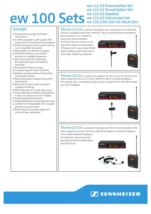
ew 100 Setsew 112 G3 Presentation Setew 122 G3 Presentation Set ew 152 G3 Headsetew 172 G3 Instrument Setew 135/145/165 G3 Vocal SetsThe ew 122 G3 is a wireless microphone set. The ew 122 G3 consists of thesame components as ew 112 G3 but with ME 4 clip-on cardioid microphone.The compact clip-on microphone rejects noises coming from the side which means less risk of feedback.The ew 152 G3 is a wireless microphone set. The ew 152 G3 consists of the same components as ew 112 G3 but with ME 3 headworn cardioid microphone.The included condenser headworn microphone is easy to wear, has great pop protection and produces powerful sound.FEATURESSturdy metal housing (transmitterand receiver)42 MHz bandwidth: 1,680 tunable UHF frequencies for interference-free reception Enhanced frequency bank system with up to 12 compatible frequenciesHigh-quality true diversity reception Automatic frequency scan feature searches for available frequencies Pilot tone squelch for eliminating RF interference when transmitter is turned offEnhanced AF frequency rangeIncreased range for audio sensitivityWireless synchronization of transmitters via infrared interfaceIlluminated graphic display (transmitter and receiver)Auto-Lock function avoids accidental changing of settingsHDX compander for crystal-clear sound Transmitter feature battery indicatation in 4 steps, also shown on receiver display Programmable Mute function Integrated Equalizer and Sound c heck mode Contacts for recharging BA 2015 accupack directly in the transmitterWide range of accessories adapts the system to any requirementThe ew 112 G3 is a wireless microphone set, consisting of a True Diversityreceiver, a bodypack transmitter with ME 2 clip-on omni-directional microphone plus accessories. It is versatile for every style of presentations.A wireless link from receiver to the transmitter allows synchronization of frequencies for easy setup. Backlit graphic displays make them easy to read under all lighting conditions.The ew 135 G3 is a wireless microphone set, consisting of a True Diversityreceiver, a handheld transmitter with e 835 microphone head plus accessories. It is versatile for every style of music and presentations. A wireless link from receiver to the transmitter allows synchronization of frequencies for easy setup. Backlit graphic displays make them easy to read under all lighting conditions.The ew 145 G3 consists of the same components as ew 135 G3but with an e 845 microphone head.The ew 165 G3 consists of the same components as ew 135 G3but with an e 865 microphone head.FEATURESew 135 G3/ew 145 G3/ ew 165 G3 Vocal SetsSee above mentioned list of features plus Handheld transmitter with easy-exchangeable microphone heads from evolution seriesThe ew 172 G3 is a wireless instrument set, consisting of a True Diversityreceiver, a bodypack transmitter with CI 1 jack cable plus accessories. It is versatile for picking up instruments.The system features a virtual cable emulator to get sound response just like a cable, a built-in guitar tuner and an EQ. The frequency respon-se starts at 25 Hz for natural bass reproduction.ARCHITECT’S SPECIFICATIONSew 112 G3 Presentation SetComplete plug & play wireless microphone set with clip-on microphone (permanent polarized, omni-directional) for multi-purpose application. The devices shall have metal housings for rugged use. 42 MHz bandwidth with 1,680 tunable frequencies. 20 banks with up to 12 compatible frequencies, 1 bank for individual selectable frequencies. Scan function and wireless synchronization to the transmitter for easy setup. HDX compander delivers high-quality sound performance. The transmitter shall have a sensitivity range of 48 dB. The receiver offers a maximum output level of +18 dBu (+6 dB gain). True Diversity and pilot tone squelch for interference-free reception.The transmitter shall have a programmable Mute switch (RF on/off, AF on/off, disabled)Charging contacts on transmitter for recharging BA 2015 accu pack directly in the transmitter shall be available. 3-step battery + Low-Battery indication on transmitter and receiver shall give reliable information on operation time. Menu operation, auto-lock function and illuminated graphic displays on transmitter and receiver for user-friendly operation.A RF Mute function on transmitter and receiver allows offline settings. An equalizer and soundcheck mode is integrated in the receiver.A wide range of clip-on and headworn microphones and accessories shall be available for the system. The wireless microphone system shall feature a true-diversity receiver with 42 MHz of available tuning bandwidth with a total of 1,680 frequencies accessible in 25 kHz steps. The wireless microphone receiver must feature one balanced XLR output with a max. output of +18 dBu, and one unbalanced ¼” output with a max. output of +12 dBu. The wireless microphone receiver must feature two BNC antenna inputs, one for each receiver module in the true diversity system.The wireless microphone receiver must feature an automatic frequency scanning function that utilizes twenty (20) banks of pre-coor-dinated frequencies that are free of intermodulation interference. The wireless microphone receiver must also feature a user bank in order to store user defined frequencies. The wireless microphone transmitter must operate on two 1.5 V AA battery cells. The wireless microphone transmitter must have access to 1,680 frequencies tuned in 25 kHz steps across a defined 42 MHz bandwidth. The wireless microphone transmitter must feature a backlit display that displays frequency information, AF level, battery level. The wireless micro-phone transmitter must transmit a pilot-tone squelch. The wireless microphone transmitter must have a specified RF output power of 30 mW. The wireless microphone receiver must accept 12 V DC power via BNC antenna inputs.ew 122 G3 Presentation SetComplete plug & play wireless microphone set with clip-on microphone (condenser, cardioid) from Sennheiser evolution series for multi-purpose application. Further discription see paragraph ew 112 G3.ew 152 G3 Head SetComplete plug & play wireless microphone set with headworn microphone (permanent polarized, cardioid) for hands-free application. Further discription see paragraph ew 112 G3.ew 172 G3 Head SetComplete plug & play wireless instrument set from Sennheiser evolution series for multi-purpose application.Further discription see paragraph ew 112 G3.ew 135 G3 Vocal SetComplete plug & play wireless microphone set with easy-exchangeable e 835 microphone head (dynamic, cardioid) from Sennheiser evolution series for multi-purpose application. Further discription see paragraph ew 112 G3.ew 145 G3 Vocal SetComplete plug & play wireless microphone set with easy-exchangeable e 845 microphone head (dynamic, super-cardioid) from Sennheiser evolution series for multi-purpose application. Further discription see paragraph ew 112 G3.ew 165 G3 Vocal SetComplete plug & play wireless microphone set with easy-exchangeable e 865 microphone head (electret-condenser, super-cardioid) from Sennheiser evolution series for multi-purpose application. Further discription see paragraph ew 112 G3.SySTEMRF frequency range ................................................ 516…865 MHz1,785....1,800 MHzTransmission/receiving frequencies ................... 512.....1,865 MHz: 1,6801,785....1,800 MHz: 1,500Presets (12)Switching bandwidth ............................................. 512.....1,865 MHz: 42 MHz1,785....1,800 MHz: 15 MHzCompander ...............................................................HDXFrequency response ...............................................25…18,000 HzSignal-to-noise ratio ..............................................> 110 dB(A)THD, total harmonic distortion ............................< 0,9 %RECEIVERSTrue diversityAntenna connector .................................................2 x BNC, 50 OAudio output level (balanced) .............................XLR: +18 dBu maxAudio output level (unbalanced) ........................Jack: +12 dBu maxDimensions ...............................................................202 x 212 x 43 mmWeight .......................................................................~ 900gTRANSMITTERRF output power .....................................................typ. 30 mW battery AA (Mignon)Power supply............................................................2 x AA batteriesOperating time ........................................................typ. 8hInput voltage range mic ........................................1.8 V effInput voltage range line ........................................3 V effDimensions ...............................................................82 x 64 x 24 mmWeight .......................................................................~ 160gContinued on page 5Microphones (SK 100)ME 2ME 3-ew ME 4Microphone type .............................condenser condenser condenserSensitivity .........................................20 mV/Pa 1.6 mV/Pa40 mV/PaPick-up pattern ................................omni-directional cardioid cardioidMax. SPL ............................................130 dB SPL150 dB SPL120 dB SPL Microphone heads (SKM 100)MMD 835-1MMD 845-1MMK 865-1Radio microphone type .................dynamic dynamic condenserSensitivity ......................................... 2.1 mV/Pa 1.6 mV/Pa 1.6 mV/PaPick-up pattern ................................cardioid super-cardioid cardioid/super-cardioid,switchableMax. SPL ............................................154 dB SPL154 dB SPL152 dB SPL Frequency response .......................80.....18,000 Hz80.....18,000 Hz80.....18,000 HzDELIVERY INCLUDES for ew 112 / ew 122 / ew 152 / ew 172 G31 EM 100 G3 rack-mount receiver1 SK 100 G3 bodypack transmitter1 ME2 clip-on microphone (omni-directional) (ew 112) or1 ME 4 clip-on microphone (cardioide) (ew 122) or1 ME 3-ew headset microphone (cardioid) (ew 152) or1 CI instrument cable (ew 172)1 NT2 power supply unit2 Antennas2 Stacking elements2 AA batteries1 Instruction ManualDELIVERY INCLUDES for ew 135 / ew 145 / ew 165 G31 S KM 100-835 G3 handheld transmitterwith cardioid dynamic head or1 S KM 100-845 G3 handheld transmitterwith super-cardioid dynamic head or1 S KM 100-865 G3 handheld transmitterwith super-cardioid condenser head1 EM 100 G3 rack receiver1 MZQ 1 microphone clip1 NT2 power supply unit2 Antennas2 Stacking elements2 AA batteries1 Instruction ManualPOLAR PATTERN0510152025dB30°30°60°60°90°90°120°150°120°150°0°180°125 Hz 250 Hz 500 Hz 1000 Hz2000 Hz 4000 Hz 8000 Hz 16000 HzME 3-ewME 4-ewMMD 835-1MME 865-1MMD 845-10510152025dB30°30°60°60°90°90°120°150°120°150°0°180°125 Hz 250 Hz 500 Hz 1000 Hz2000 Hz 4000 Hz 8000 Hz 16000 Hz0510152025dB30°30°60°60°90°90°120°150°120°150°0°180°125 Hz 250 Hz 500 Hz 1000 Hz2000 Hz 4000 Hz 8000 Hz 16000 Hz0510152025dB30°30°60°60°90°90°120°150°120°150°0°180°125 Hz 250 Hz 500 Hz 1000 Hz2000 Hz 4000 Hz 8000 Hz 16000 Hz0510152025dB30°30°60°60°90°90°120°150°120°150°0°180°125 Hz 250 Hz 500 Hz 1000 Hz2000 Hz 4000 Hz 8000 Hz 16000 Hzew 112 G3 Presentation Set Cat. No. ew 112 G3-A-EU 516...558 MHz 503100 ew 112 G3-A-US 516...558 MHz 503169 ew 112 G3-A-UK 516...558 MHz 503170 ew 112 G3-G-EU 566...608 MHz 503171 ew 112 G3-G-US 566...608 MHz 503172 ew 112 G3-G-UK 566...608 MHz 503173 ew 112 G3-B-EU 626...668 MHz 503174 ew 112 G3-B-US 626...668 MHz 503175 ew 112 G3-B-UK 626...668 MHz 503176 ew 112 G3-C-EU 734...776 MHz 503177 ew 112 G3-C-US 734...776 MHz 503178 ew 112 G3-C-UK 734...776 MHz 503179 ew 112 G3-D-EU 780...822 MHz 503180 ew 112 G3-D-EU-X 780...822 MHz 503181 ew 112 G3-D-UK 780...822 MHz 503182 ew 112 G3-E-EU 823...865 MHz 503183 ew 112 G3-E-EU-X 823...865 MHz 503184 ew 112 G3-E-UK 823...865 MHz 503185 ew 112 G3-GB 606…648 MHz 504638 ew 112 G3-1G8 1,785…1,800 MHz504900 ew 122 G3 Presentation Set Cat. No. ew 122 G3-A-EU 516...558 MHz 503101 ew 122 G3-A-US 516...558 MHz 503187 ew 122 G3-A-UK 516...558 MHz 503188 ew 122 G3-G-EU 566...608 MHz 503189 ew 122 G3-G-US 566...608 MHz 503190 ew 122 G3-G-UK 566...608 MHz 503191 ew 122 G3-B-EU 626...668 MHz 503192 ew 122 G3-B-US 626...668 MHz 503193 ew 122 G3-B-UK 626...668 MHz 503194 ew 122 G3-C-EU 734...776 MHz 503195 ew 122 G3-C-US 734...776 MHz 503196 ew 122 G3-C-UK 734...776 MHz 503197 ew 122 G3-D-EU 780...822 MHz 503198 ew 122 G3-D-EU-X 780...822 MHz 503199 ew 122 G3-D-UK 780...822 MHz 503200 ew 122 G3-E-EU 823...865 MHz 503201 ew 122 G3-E-EU-X 823...865 MHz 503202 ew 122 G3-E-UK 823...865 MHz 503203 ew 122 G3-GB 606…648 MHz 504639 ew 122 G3-1G8 1,785…1,800 MHz504901ew 152 G3 Presentation Set Cat. No.ew 152 G3-A-EU 516...558 MHz 503102ew 152 G3-A-US 516...558 MHz 503205ew 152 G3-A-UK 516...558 MHz 503206ew 152 G3-G-EU 566...608 MHz 503207ew 152 G3-G-US 566...608 MHz 503208ew 152 G3-G-UK 566...608 MHz 503209ew 152 G3-B-EU 626...668 MHz 503210ew 152 G3-B-US 626...668 MHz 503211ew 152 G3-B-UK 626...668 MHz 503212ew 152 G3-C-EU 734...776 MHz 503213ew 152 G3-C-US 734...776 MHz 503214ew 152 G3-C-UK 734...776 MHz 503215ew 152 G3-D-EU 780...822 MHz 503216ew 152 G3-D-EU-X 780...822 MHz 503217ew 152 G3-D-UK 780...822 MHz 503218ew 152 G3-E-EU 823...865 MHz 503219ew 152 G3-E-EU-X 823...865 MHz 503220ew 152 G3-E-UK 823...865 MHz 503221ew 152 G3-GB 606…648 MHz 504640ew 152 G3-1G8 1,785…1,800 MHz504902ew 172 G3 Instrument Set Cat. No.ew 172 G3-A-EU 516...558 MHz 503103ew 172 G3-A-US 516...558 MHz 503223ew 172 G3-G-EU 566...608 MHz 503224ew 172 G3-G-US 566...608 MHz 503225ew 172 G3-B-EU 626...668 MHz 503226ew 172 G3-B-US 626...668 MHz 503227ew 172 G3-C-EU 734...776 MHz 503228ew 172 G3-C-US 734...776 MHz 503229ew 172 G3-D-EU 780...822 MHz 503230ew 152 G3-D-EU-X 780...822 MHz 503231ew 172 G3-D-UK 780...822 MHz 503332ew 172 G3-E-EU 823...865 MHz 503233ew 172 G3-E-EU-X 823...865 MHz 503234ew 172 G3-E-UK 823...865 MHz 503235ew 152 G3-GB 606…648 MHz 504641ew 152 G3-1G8 1,785…1,800 MHz504903Continued on page 10ew 135 G3 Vocal Set Cat. No. ew 135 G3-A-EU 516...558 MHz 503104 ew 135 G3-A-US 516...558 MHz 503237 ew 135 G3-A-UK 516...558 MHz 503238 ew 135 G3-G-EU 566...608 MHz 503239 ew 135 G3-G-US 566...608 MHz 503240 ew 135 G3-G-UK 566...608 MHz 503241 ew 135 G3-B-EU 626...668 MHz 503242 ew 135 G3-B-US 626...668 MHz 503243 ew 135 G3-B-UK 626...668 MHz 503244 ew 135 G3-C-EU 734...776 MHz 503245 ew 135 G3-C-US 734...776 MHz 503246 ew 135 G3-C-UK 734...776 MHz 503247 ew 135 G3-D-EU 780...822 MHz 503248 ew 135 G3-D-EU-X 780...822 MHz 503249 ew 135 G3-D-UK 780...822 MHz 503250 ew 135 G3-E-EU 823...865 MHz 503251 ew 135 G3-E-EU-X 823...865 MHz 503252 ew 135 G3-E-UK 823...865 MHz 503253 ew 135 G3-GB 606…648 MHz 504642 ew 135 G3-1G8 1,785…1,800 MHz504904 ew 145 G3 Vocal Set Cat. No. ew 145 G3-A-EU 516...558 MHz 503105 ew 145 G3-A-US 516...558 MHz 503255 ew 145 G3-G-EU 566...608 MHz 503256 ew 145 G3-G-US 566...608 MHz 503257 ew 145 G3-B-EU 626...668 MHz 503258 ew 145 G3-B-US 626...668 MHz 503259 ew 145 G3-C-EU 734...776 MHz 503260 ew 145 G3-C-US 734...776 MHz 503261 ew 145 G3-D-EU 780...822 MHz 503262 ew 145 G3-D-EU-X 780...822 MHz 503263 ew 145 G3-D-UK 780...822 MHz 503264 ew 145 G3-E-EU 823...865 MHz 503265 ew 145 G3-E-EU-X 823...865 MHz 503266 ew 145 G3-E-UK 823...865 MHz 503267 ew 145 G3-GB 606…648 MHz 504643 ew 145 G3-1G8 1,785…1,800 MHz504905ew 165 G3 Vocal Set Cat. No. ew 165 G3-A-EU 516...558 MHz 503106 ew 165 G3-A-US 516...558 MHz 503269 ew 165 G3-G-EU 566...608 MHz 503270 ew 165 G3-G-US 566...608 MHz 503271 ew 165 G3-B-EU 626...668 MHz 503272 ew 165 G3-B-US 626...668 MHz 503273 ew 165 G3-C-EU 734...776 MHz 503274 ew 165 G3-C-US 734...776 MHz 503275 ew 165 G3-D-EU 780...822 MHz 503276 ew 165 G3-D-EU-X 780...822 MHz 503277 ew 165 G3-D-UK 780...822 MHz 503278 ew 165 G3-E-EU 823...865 MHz 503279 ew 165 G3-E-EU-X 823...865 MHz 503280 ew 165 G3-E-UK 823...865 MHz 503281 ew 165 G3-GB 606…648 MHz 504644 ew 165 G3-1G8 1,785…1,800 MHz504906RECOMMENDED ACCESSORIESCat. No. Earworn microphones, 3.5 mm jack plugomni:black Ear Set 1-ew504232 beige Ear Set 1-ew-3 504233cardioid:black Ear Set 4-ew504236 beige Ear Set 4-ew-3504237Clip-on microphones, 3.5 mm jack plug omni:black MKE 1-ew502876 white MKE 1-ew-1502877 brown MKE 1-ew-2502878 beige MKE 1-ew-3502879 black MKE 2-ew Gold009831 beige MKE 2-ew-3 Gold 009832 black MKE 40-ew500527Headmicrophones thin connection cable, 3.5 mm jack plugomni:black HSP 2-ew009866 beige HSP 2-ew-3009872 cardioid:black HSP 4-ew009867 beige HSP 4-ew-3009873Headmicrophones thin connection cable, 3.5 mm jack plug, shorter microphone boom and smaller neckbandomni:black HSP 2-ew-M500693 beige HSP 2-ew-3-M500692 cardioid:black HSP 4-ew-M500699 beige HSP 4-ew-3-M500698Antenna Splitter for 1800 MHz – ASA 1-1G8504914 Antenna Booster for 1800 MHz – AB 3-1G8504915 Directional Antenna for 1800 MHz – AD 1800504916 19“ RackMount Kit – GA 3503167 Antenna Front Mount Kit – AM 2009912 Power supply for one L 2015NT 1-1-EU (EU version, 230 V) 503158 NT 1-1-UK (UK version, 230 V) 503874 NT 1-1-US (US version, 120 V) 503873 Power supply for up to three L 2015NT 3-1-EU (EU version, 230 V) 503159 NT 3-1-UK (UK version, 230 V) 503877 NT 3-1-US (US version, 120 V) 503876 GA 3 – Rack-mount kit 503167 AM 2 – Antenna Mount kit 009912 CC 3 – System Case 503168 L 2015 – Charging unit 009828 BA 2015 – Rechargeable battery pack 009950Cat. No. ASA 1 – Active antenna splitter 503165 A 1031 – Antenna 004645 A 2003 – Passive directional antenna 003658 AB 3 – Antenna booster 021822 ME 4 – Clip-on microphone, cardioid, black 503156 CI 1 – Instrument cable 503163 ew 135 / ew 145 / ew 165 G3 Vocal SetsMMD 835-1 – evolution microphone head 502575 MMD 845-1 – evolution microphone head 502576 MME 865-1 – evolution microphone head 502581 MZW 1 – Windshield 004839 KEN 2 – Identification rings 530195 LA 2 – Charging adapter forhandheld microphones 503162 CC 3 – System case 503168Sennheiser electronic GmbH & Co. KG Am Labor 1, 30900 Wedemark, Germany 0 4 / 1 3 S e n n h e i s e r i s a r e g i s t e r e d t r a d e m a r k o f S e n n h e i s e r e l e c t r o n i c G m b H & C o . K G . w w w . s e n n h e i s e r . c o m . C o p y r i g h t ©0 4 / 2 0 1 3 . A l l r i g h t s r e s e r v e d . E r r o r s a n d o m i s s i o n s e x c e p t e d .ew 100 SetsContact your local Service Partner:。
摩托罗拉通讯设备 SPECTRA 系列产品部件清单说明书
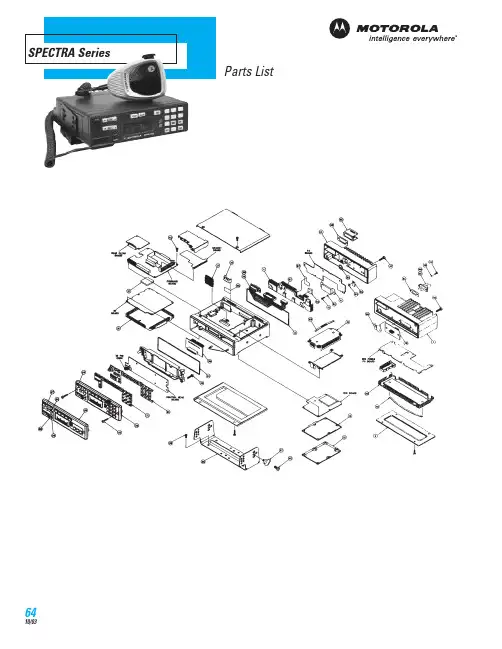
SPECTRA SeriesParts ListParts ListREF.NO.PART NO.DESCRIPTION REF.NO.PART NO.DESCRIPTION12680010M02Heatsink, 30-watt22680009M03Heatsink, 12-watt32680105N01Shield, 30-watt PA board 42680011M01Shield, 12-watt PA board 51580048N01Cover, 30-watt PA6---Shield, power module8---Gasket, heatsink111580098L01Shield, receiver front end 121580097L01Cover, VCO board143280247N01Gasket, VCO151580099L01Shield, RF board172880260M01Header, floating184280007M01Clip, regulator223080239N02Cable, PA ribbon250180016R09Housing, front cover, with keypad 261580010P02Housing, front cover, without keypad 273805670X04Pushbutton Rocker, “MODE”283805670X03Pushbutton Rocker, “VOLUME”293880092J01Key, “DIM”303880092J02Key, “HOME”317580189L03Keypad330310945A14Screw, tapping; 6 used 343280289L02Gasket, housing370384244C06Screw, machine, wing(5.0 x 0.8 x 10)380780086N02Trunnion, mounting 390300136756Screw, tapping, instl hrdwr(10-16 x 5⁄8) (6)400310908B08Screw, machine, instl hrdwr(5.0 x 0.8 x 10) (4)410310911A11Screw, machine (3.0 x 0.5 x 8.0); 12W-3 ,30W-5 used42---Screw, tapping (3.5 x 0.6 x 8.0) (board mtg) 440380043L01Screw, metric (3.0 x 10); 44 used 450380077M01Screw, control head mount; 2 used 460380077M02Screw, hex socket (30-watt); 2 used 470380077M03Screw, hex socket (12-watt); 2 used48---Screw (3.5 x 0.6 x 46) 490400131974Washer, flat (.130 x .312 x .030); 2 used 500480017F01Washer, pivot; 2 used517582200H01Pad; 3 used52---Washer, compression; 3 used 530484180C01Washer, shoulder550980272N02Connector, POW56---Insulator, regulator58---Insulator, alumina602680186M01Shield, 30-watt PA613280015M01Gasket, power connector623280088M01Gasket, accessory connector 643880227M04Cap. On/Off Switch654280016M03Clip, accessory connector674280265M02Clip, coax, 12-watt PA; 2 used 695584300B01Handle; 8 used705584300B04Handle716180017S01Lightpipe726480108R01Assembly, PA feedthrough, 30-wattHMN1050D Desk Top Microphone (for control station operation)HLN1220B Handset with Hang Up Box HMN1053BHSN4018BHMN1050DRLN4075A Radio Mount with Hardware RLN4076A Vehicle Mount with HardwareRLN4077A Angle Bracket with 20°Fixed Angle and 50°Swivel RLN4078A Flat Bracket with 50°SwivelMiscellaneous HardwareHLN6025A Key Lock Mount HLN6008A Remote Mount Kit, with 17 Foot CableAntennas800 MHzHAF4002A 1/4 Wave, roof top (806-900 MHz)RRA4983A 3dB, roof top (806-900 MHz)900 MHzRRA4935A 3dB, roof top w/14 ft. cable (890-960 MHz)RAF4003ARM 3dB, roof top w/22 ft. cable (890-960 MHz)VHFHAD4006A 1/4 Wave, roof top (136-144 MHz)HAD4007A 1/4 Wave, roof top (144-152 MHz)HAD4008A 1/4 Wave, roof top (150.8-162 MHz)HAD4009A 1/4 Wave, roof top (162-174 MHz)RAD4010ARB 3dB, roof top (136-174 MHz)UHFHAE4002A 1/4 Wave, roof top (403-430 MHz)HAE4003A 1/4 Wave, roof top (450-470 MHz)HAE4004A 1/4 Wave, roof top (470-512 MHz)HAE4010A 3.5dB, roof top (406-420 MHz)HAE4011A 3.5dB, roof top (450-470 MHz)HAE4012A 3.5dB, roof top (470-495 MHz)HAE4013A 3.5dB, roof top (494-512 MHz)HLN6025AHAE4003ARRA4935A6680387A70T-6 Torx Bit6680387A72T-8 Torx Bit6680387A74T-10 Torx Bit6680387A75T-15 Torx Bit6680387A77T-25 Torx BitMagnetic Screwdriver0180320B16Magnetic Screwdriver Set with BitsInsertion andExtraction ToolInstalls and/or removes wires fromaccessory connector.6680163F01Insertion and ExtractionToolHex L-Shaped Key SetRecommended for front panel and PA removal/installation. 10 pieceset from 1.27mm to 6mm.0180370B87Metric Hex L-Shaped Key SetRVN4001N Programming Software, 3-1⁄2˝ Diskette (includes binderand manual)RailroadRVN4099B Programming Software, 3-1⁄2˝ Diskette (includes binderand manual)Radio Interface BoxLinks radio programming cable andcomputer interface together. Providesrequired voltage shift to enablecommunications between radio andcomputer. Requires computer interface cable, radio programmingcable, and a 9 volt snap type battery (6082728J01) or wall mountpower supply. Order separately.RLN4008E Radio Interface BoxRSX4043A6680387A706680387A746680163F01RLN4008ERF Service Cables3080373B25RF Injection Board Output Cable. Connects to the RX injection output of the VCO assembly for testing RF injection level 3080373B26BNC (M) to SMB (M) Cable3080373B41BNC (F) to Taiko-Denki (M) Cable3080373B27BNC (M) to Taiko-Denki (F) AdapterTKN8531C Key-Variable Loader Cable5880384G68SMA to BNC Adapter5880367B21Mini-UHF Male to ‘N’ Female Adapter Programming CableRequired to program radio, acts as a link between RIB box and Radio.3080369B73Programming CableService Manuals6881076C20Astro Digital SPECTRA BasicService Manual, VHF, UHF, 800 MHz 6881076C25Astro Digital SPECTRA Detailed ServiceManual, VHF, UHF, 800 MHz6880101W33SPECTRA Detailed Service Manual 6881074C45SPECTRA Service Manual, 800 MHz 6880101W37SPECTRA Service Manual, 900 MHz 6881070C95SPECTRA Service Manual, VHF 6880101W39SPECTRA Service Manual, UHF 6880102W33SPECTRA Service Manual, Securenet。
KPX 100可编程密码键盘指南说明书

∙∙∙∙D.A.P. Reset seePage 5∙∙∙∙∙∙∙∙∙????#*This must be done after DAP resetRecord the new code0 0 0 0*Set system into programming mode with factory set master code.8 9 0 0 8 9 0 1 # #Set system to single user mode, clear all previous data & refreshes system Set system to multi user mode, clear all previous data & refreshes system4 0 4 1 4 2 1 to 999# # # Output 1 in momentary mode from 1 to 999 seconds Output 1 in Start / Stop Mode (toggle) Output 1 in Start / Stop Mode (toggle) with accelerated code5 0 5 1 5 21 to 999 # # #Output 2 in momentary mode from 1 to 999 seconds Output 2 in Start / Stop Mode (toggle) Output 2 in Start / Stop Mode (toggle) with accelerated code0 2# # #4 digits, fixed 4 digits, fixed 4 digits, fixedPersonal Master Code & Super User CodeUser Code 1 for output 1 with Duress Code function User code 2 for output 21 Personal Master Code & Super User Code # 100 User codes in Group 1 for output 1 with Duress Code function0 1 2 00 to 99 0 to 94 to 8 digits4 to 8 digits 4 to 8 digits10 User Codes in Group 2 for output 2##i)ii)7 0 7 1 7 27 6 5 to 1000 # # ##After 10 successive false codes, keypad will lock for 30 secondsAfter 10 successive false codes, the Duress output switches to groundSelectable from 5 to 10 successive false codes, the keypad locks for 15 minutes. The keypad can be reset to release lock with the Master Code at any time during the locking period. Removal of all above security settings8 0 8 0 # #1 0Door Forced Open Alarm is Activated Door Forced Open Alarm is Disabled8 11 #1 second notification beep is given to notify the person outside to open the door when output relay is activated with a user code or egressbutton. Good for the locking device that gives no sound when it activates, such as magnetic lock. 8 1 0 #Notification beep disabled and replaced by 2 short successful code entry beeps for valid user codes.8 2 1 #Auto Entry Mode is selected. Key that followsthe user code is not required in code entry. The usercodes must be set in the same digit length as theMaster Code in Auto Entry mode and the code can be 4-8 digits82#Manual Entry Mode is selected. Key that followsthe user code is required in code entry. The user codescan be 4-8 digits and are not required to be the samelength as the Master Code.##8 3 8 3 1 0# #Tones are active on key pressTones are off. Use for silent environment requirements9 9# #No Propped Open AlarmTime from 1 to 999 seconds until door propped open activates alarm0 1 to 999*Keypad exits programming mode and returns to normal operationMASTER CODE*8 9 0 0#MASTER CODE*891#*MASTER CODE*LOCATION 1#OPTIONLOCATION n#OPTION n*0 0 0 0 * ----------- 8 9 0 0 # -----------0 3 2 8 9 1 8 3 2 1 # # --- --- 2 6 8 5 4 # ---4 0 1#Output 1 has been set to momentary mode with 1 second duration5 1 # ------------------- O utput 2 has been set to Start / Stop (toggle) mode7 21 0# ---------* ----------------------------*#8321685 4------------------ Output 1 activates for 1 secondOutput 2 Starts or Stops (toggle mode)#83 2 1 --------- Output 1 activates for 1 second 8 3 2 1--------- Output 2 Starts or Stops (toggle mode)# # 1 2 0 3 2 1--------- Duress output activates (output switches to (-) ground) & Output 1activates for 1 second8 3 #8 3 2 1--------- --------- Output 1 starts Output 1 stops3 2 8 9---------Lockout is reset and keypad resumes normal operation#0 0 0 0 --------- System is set to programming mode using factory set Master User Code * 8 9 0 1 --------- System is set to Multi-User Mode *8 (see note (a) below#0 3 2 8 -------- 3289 has been stored as the new Personal Master Code & Super User Code# 9 1 8 3 2 -------- 8321 has been stored as 1st user code in Group 1 with duresscode function# 1 0 11 3 32 --------33221 has been stored as 3rd user code in Group 1 withduress code function# 2 0 3 1 2 6 8 -------- 6854 has been stored as 1st user code in Group 2# 5 1 4 2 5 4 3 -------- 54321 has been stored as 2nduser code in Group 2#2 2 1 4 ---------------------------- Output 1 is set to Momentary Mode with 1 second duration#0 1 5 --------------------------------- Output 2 is set to Toggle Mode#1 7 ------------------------- Keypad is set to lock for 15 minutes after 10 successive falsecodes# 21 0* -----------------------------------##8 3 2 1 # ----------------------------------- Output 1 activates for 1 second1 12 1 # ------------------------------- Output 1 activates for 1 second3 3 3 2 2 # ------------------------------- Output 1 activates for 1 second1#6 8 5 4 # ----------------------------------- Output 2 Starts or Stops (toggle mode)5 4 3 2 Output 2 Starts or Stops (toggle mode)1#-------------------- 1 1 1 2 --------11223 has been stored as 2nd user code in Group 1 withduress code function# 2 0 2 3#------------------------------- 0 3 2 1 # --- Duress output activates (switches to ground) & Output 1 activates for 1 second3 1 2 2 # ---D uress output activates 9 switches to ground) & Output 1 activates for 1 second 3 5 3 2 2 # ---D uress output activates 9 switches to ground) & Output 1 activates for 1 second 18 3 #8 3 2 1 -------------------- ------------- Output 1 starts Output 1 StartsOutput 1 Stops1 1Output 1 Starts1 12 2---------Output 1 Stops3###3 2 8 9 # ------------------------------- Output 1 activates for 1 second 1 3 2 8 9# ------------------------------- Output 2 Starts or Stops (toggle mode)23 2 8 9 --------- Lockout is reset and keypad resumes normal operation#* *3 2 8 9 --------- Keypad is now in Programming Mode#1 0 5 #2 3 #*∙∙∙∙∙∙∙∙∙∙∙∙(B) DOOR SENSa) Door Auto Relock – the system willimmediately re-lock the door after a validaccess has been gained to prevent “tailgate”entry.b) Door Forced-open alarm – The keypad willgenerate an instant alarm if the door isforced to open. Enable the function withProgram Option 801c) Door Propped Open Alarm – The keypadwill generate an alarm if the door is leftopen longer than the pre-set time. Enablethe function with Program Option 9 withduration of 1 to 999 seconds.With the help of a normally closed door d) Inter-lock Control – When the door is open Position sensor (usually a magnetic door the inter-lock output of the keypad will give switch) o n the door to set up the following a (-) command to de-activate the other functions. keypad in an inter-lock system.∙∙∙∙。
KIT-Z100 快速入门指南说明书
Scan for full manualKIT-Z100 Quick Start GuideThis guide helps you install and use your KIT-Z100 for the first time.Go to /downloads/KIT-Z100 to download the latest user manual and check if firmware upgrades are available.Step 1: Check what’s in the packageECU-Z1001 19V DC power adapter and cord 1 Quick start guide KT-107Z/KT-107ZRB (with restricted BW, up to 5.35GHz) 1 5.2V power adapter and cord Tabletop mount On-wall mount unit 1 C-USB/Micro B cableInstallation screwsPanel Mount plate1 right-angle OTG USB cableStep 2: Get to know your KIT-Z100ECU-Z100KT-107Z/KT-107ZRBBoth Table-top mount and wall mount include the following connectors: • A power connector, when notusing the PoE Ethernet port. • PoE RJ-45 Ethernet Port toconnect to an Ethernet cable. • A USB connector:▪ For the table-top mount, aMicro-USB port, forconnecting an external USB device (for example, a headset or memory disk). ▪ For the wall mount, a Type AUSB port is available using the right-angle OTG USB cable (included).Step 3: Mount ECU-Z100Install ECU-Z100 using one of the following methods:• Attach the rubber feet and place the unit on a flat surface.• Fasten a bracket (included) on each side of the unit and attach it to a flat surface(see /downloads/KIT-Z100).• Mount the unit in a rack using the recommended rack adapter(see /product/KIT-Z100).• Ensure that the environment (e.g., maximum ambient temperature &air flow) is compatible for the device. • Avoid uneven mechanical loading.• Appropriate consideration of equipment nameplate ratings should be used for avoiding overloading of the circuits.• Reliable earthing of rack-mounted equipment should be maintained.Step 4: Mount KT-107Z/KT-107ZRBMounting on a table using one of the following options:Portable Mount: place the tabletop mount on the table. Connected cables remain visible and the table remains intact. Secure Mount: secure the tabletop mount to the table as follows:1. Measure the exact location on the surface of the table where you want to install the KT-107Z/KT-107ZRB.2. Drill a hole in the table and optionally cut the cable pass-through opening according to the cut-out dimensions definedin the user manual.3. Secure the tabletop mount to the table using the M5x60 secure screw.4. Connect the Ethernet port to a PoE-enabled source. Optionally, you can connect the power adapter too (as backup).5. Replace the appropriate cover and place the KT-107Z/KT-107ZRB over the tabletop mount (the is magnetically heldin place), by first inserting the lower part of the then carefully laying the KT-107Z/KT-107ZRB in place.6. Wait for the Home-page to load and then secure the KT-107Z/KT-107ZRB to the tabletop mount from the rear side(using 2 M2x4 screws, supplied with the unit).7. Optionally, lock the tabletop mount with a Kensington locker (not supplied).Mounting on the wall:Before mounting KIT-Z100 on a wall, install an in-wall junction box (recommended boxes are listed in the user manual)1. Attach the on-wall mount unit to the installed junction box (top side up see indication arrows on unit).Connect Ethernet and/or power cables and optionally, insert the right-angle USB cable (supplied) for connecting to an adjacent external USB device.2. Screw the 4 wall-mounting screws (supplied) through the screw openings.The various screw openings fit various types of wall junction boxes.3. On the rear side of the KT-107Z/KT-107ZRB, remove the screwcover and the cover (by slightly pressing downwards and thenpulling out) and set aside.4. Attach the panel mount plate to the rear side of theKT-107Z/KT-107ZRB (using 4 M2x4 screws, supplied).5. Connect the flat cable from the on-wall mount (attached to thein-wall junction box) to the connector on the rear ofKT-107Z/KT-107ZRB.6. Hang the KT-107Z/KT-107ZRB on the wall by sliding the tabs onthe attached panel mount plate over the grooves on the on-wallmount unit.Step 5: Connect inputs and outputsAlways switch OFF the power on each device before connecting it to your KIT-Z100.To achieve specified extension distances, use the recommended Kramer cables available at/product/KIT-Z100. Using third-party cables may cause damage!Microphone and speakers can be connected to ECU-Z100 in the following ways:•Speakers can be connected via LINE OUT connector and/or USB ports.•Microphones cab be connected via MIC IN connector (via amp) and/or USB ports.•Speakerphones (combining a speaker and a microphone) can be connected via USB ports.KT-107Z/KT-107ZRB can be powered in any of the following ways:•Using the power adapter when connected by LAN (without PoE support).•Using the power adapter when connected to LAN by Wi-Fi•By PoE when connecting to Ethernet by PoE-supporting LAN.Step 6: Connect powerConnect the power cord to ECU-Z100 and plug it into the mains electricity.If required, connect the power adapter on the KT-107Z/KT-107ZRB to the Power 2-pin terminal block connector on the tabletop mount and to the mains power.Safety Instructions (See for updated safety information)Caution:•There are no operator serviceable parts inside the unit.Warning:•Use only the power cord that is supplied with the unit.•Disconnect the power and unplug the unit from the wall before installing.•Do not open the unit. High voltages can cause electrical shock! Servicing by qualified personnel only.•To ensure continuous risk protection, replace fuses only according to the rating specified on the product label which located on the bottom of the unit.Step 7: Set and operate KIT-Z100Before setting up the application on KT-107Z/KT-107ZRB, you need to acquire Zoom Rooms licenses.To set and operate the application, go to the Zoom Rooms website at /hc/en-us.To use the Zoom Rooms widget on Kramer Control, go to Zoom Rooms settings at/manuals/kramer/kramer-control/1/en/topic/zoom-room-module.。
IATA AHM目录
Airport Handling ManualEffective 1 January—31 December 201838NOTICEDISCLAIMER. The information contained in thispublication is subject to constant review in the lightof changing government requirements and regula-tions. No subscriber or other reader should act onthe basis of any such information without referringto applicable laws and regulations and/or withouttak ing appropriate professional advice. Althoughevery effort has been made to ensure accuracy, theInternational Air Transport Association shall not beheld responsible for any loss or damage caused byerrors, omissions, misprints or misinterpretation ofthe contents hereof. Furthermore, the InternationalAir Transport Association expressly disclaims anyand all liability to any person or entity, whether apurchaser of this publication or not, in respect ofanything done or omitted, and the consequencesof anything done or omitted, by any such person orentity in reliance on the contents of this publication.Opinions expressed in advertisements appearing inthis publication are the advertiser’s opinions and donot necessarily reflect those of IATA. The mentionof specific companies or products in advertisementdoes not imply that they are endorsed or recom-mended by IATA in preference to others of a simi-lar nature which are not mentioned or advertised.© International Air Transport Association. AllRights Reserved. No part of this publication maybe reproduced, recast, reformatted or trans-mitted in any form by any means, electronic ormechanical, including photocopying, record-ing or any information storage and retrieval sys-tem, without the prior written permission from:Senior Vice PresidentAirport, Passenger, Cargo and SecurityInternational Air Transport Association800 Place VictoriaP.O. Box 113Montreal, QuebecCANADA H4Z 1M1Airport Handling ManualMaterial No.: 9343-38ISBN 978-92-9229-505-9© 2017 International Air Transport Association. All rights reserved.TABLE OF CONTENTSPage Preface (xv)Introduction (xvii)General (1)AHM001Chapter0—Record of Revisions (1)AHM011Standard Classification and Numbering for Members Airport Handling Manuals (2)AHM012Office Function Designators for Airport Passenger and Baggage Handling (30)AHM020Guidelines for the Establishment of Airline Operators Committees (31)AHM021Guidelines for Establishing Aircraft Ground Times (34)AHM050Aircraft Emergency Procedures (35)AHM070E-Invoicing Standards (53)Chapter1—PASSENGER HANDLING (91)AHM100Chapter1—Record of Revisions (91)AHM110Involuntary Change of Carrier,Routing,Class or Type of Fare (92)AHM112Denied Boarding Compensation (98)AHM120Inadmissible Passengers and Deportees (99)AHM140Items Removed from a Passenger's Possession by Security Personnel (101)AHM141Hold Loading of Duty-Free Goods (102)AHM170Dangerous Goods in Passenger Baggage (103)AHM176Recommendations for the Handling of Passengers with Reduced Mobility(PRM) (105)AHM176A Acceptance and Carriage of Passengers with Reduced Mobility(PRM) (106)AHM180Carriage of Passengers with Communicable Diseases (114)AHM181General Guidelines for Passenger Agents in Case of SuspectedCommunicable Disease (115)Chapter2—BAGGAGE HANDLING (117)AHM200Chapter2—Record of Revisions (117)AHM210Local Baggage Committees (118)AHM211Airport Operating Rules (124)Airport Handling ManualPageChapter2—BAGGAGE HANDLING(continued)AHM212Interline Connecting Time Intervals—Passenger and Checked Baggage (126)AHM213Form of Interline Baggage Tags (128)AHM214Use of the10Digit Licence Plate (135)AHM215Found and Unclaimed Checked Baggage (136)AHM216On-Hand Baggage Summary Tag (138)AHM217Forwarding Mishandled Baggage (139)AHM218Dangerous Goods in Passengers'Baggage (141)AHM219Acceptance of Firearms and Other Weapons and Small Calibre Ammunition (142)AHM221Acceptance of Power Driven Wheelchairs or Other Battery Powered Mobility Aidsas Checked Baggage (143)AHM222Passenger/Baggage Reconciliation Procedures (144)AHM223Licence Plate Fallback Sortation Tags (151)AHM224Baggage Taken in Error (154)AHM225Baggage Irregularity Report (156)AHM226Tracing Unchecked Baggage and Handling Damage to Checked and UncheckedBaggage (159)AHM230Baggage Theft and Pilferage Prevention (161)AHM231Carriage of Carry-On Baggage (164)AHM232Handling of Security Removed Items (168)AHM240Baggage Codes for Identifying ULD Contents and/or Bulk-Loaded Baggage (169)Chapter3—CARGO/MAIL HANDLING (171)AHM300Chapter3—Record of Revisions (171)AHM310Preparation for Loading of Cargo (172)AHM311Securing of Load (174)AHM312Collection Sacks and Bags (177)AHM320Handling of Damaged Cargo (178)AHM321Handling of Pilfered Cargo (179)AHM322Handling Wet Cargo (180)AHM330Handling Perishable Cargo (182)AHM331Handling and Protection of Valuable Cargo (184)AHM332Handling and Stowage of Live Animals (188)AHM333Handling of Human Remains (190)Table of ContentsPageChapter3—CARGO/MAIL HANDLING(continued)AHM340Acceptance Standards for the Interchange of Transferred Unit Load Devices (191)AHM345Handling of Battery Operated Wheelchairs/Mobility AIDS as Checked Baggage (197)AHM350Mail Handling (199)AHM351Mail Documents (203)AHM353Handling of Found Mail (218)AHM354Handling of Damaged Mail (219)AHM355Mail Security (220)AHM356Mail Safety (221)AHM357Mail Irregularity Message (222)AHM360Company Mail (224)AHM380Aircraft Documents Stowage (225)AHM381Special Load—Notification to Captain(General) (226)AHM382Special Load—Notification to Captain(EDP Format and NOTOC Service) (231)AHM383Special Load—Notification to Captain(EDP NOTOC Summary) (243)AHM384NOTOC Message(NTM) (246)Chapter4—AIRCRAFT HANDLING AND LOADING (251)AHM400Chapter4—Record of Revisions (251)AHM411Provision and Carriage of Loading Accessories (252)AHM420Tagging of Unit Load Devices (253)AHM421Storage of Unit Load Devices (263)AHM422Control of Transferred Unit Load Devices (268)AHM423Unit Load Device Stock Check Message (273)AHM424Unit Load Device Control Message (275)AHM425Continued Airworthiness of Unit Load Devices (279)AHM426ULD Buildup and Breakdown (283)AHM427ULD Transportation (292)AHM430Operating of Aircraft Doors (295)AHM431Aircraft Ground Stability—Tipping (296)AHM440Potable Water Servicing (297)AHM441Aircraft Toilet Servicing (309)Airport Handling ManualPageChapter4—AIRCRAFT HANDLING AND LOADING(continued)AHM450Standardisation of Gravity Forces against which Load must be Restrained (310)AHM451Technical Malfunctions Limiting Load on Aircraft (311)AHM453Handling/Bulk Loading of Heavy Items (312)AHM454Handling and Loading of Big Overhang Items (313)AHM455Non CLS Restrained ULD (316)AHM460Guidelines for Turnround Plan (323)AHM462Safe Operating Practices in Aircraft Handling (324)AHM463Safety Considerations for Aircraft Movement Operations (337)AHM465Foreign Object Damage(FOD)Prevention Program (340)Chapter5—LOAD CONTROL (343)AHM500Chapter5—Record of Revisions (343)AHM501Terms and Definitions (345)AHM503Recommended Requirements for a New Departure Control System (351)AHM504Departure Control System Evaluation Checklist (356)AHM505Designation of Aircraft Holds,Compartments,Bays and Cabin (362)AHM510Handling/Load Information Codes to be Used on Traffic Documents and Messages (368)AHM513Aircraft Structural Loading Limitations (377)AHM514EDP Loading Instruction/Report (388)AHM515Manual Loading Instruction/Report (404)AHM516Manual Loadsheet (416)AHM517EDP Loadsheet (430)AHM518ACARS Transmitted Loadsheet (439)AHM519Balance Calculation Methods (446)AHM520Aircraft Equipped with a CG Targeting System (451)AHM530Weights for Passengers and Baggage (452)AHM531Procedure for Establishing Standard Weights for Passengers and Baggage (453)AHM533Passengers Occupying Crew Seats (459)AHM534Weight Control of Load (460)AHM536Equipment in Compartments Procedure (461)AHM537Ballast (466)Table of ContentsPageChapter5—LOAD CONTROL(continued)AHM540Aircraft Unit Load Device—Weight and Balance Control (467)AHM550Pilot in Command's Approval of the Loadsheet (468)AHM551Last Minute Changes on Loadsheet (469)AHM561Departure Control System,Carrier's Approval Procedures (471)AHM562Semi-Permanent Data Exchange Message(DEM) (473)AHM564Migration from AHM560to AHM565 (480)AHM565EDP Semi-Permanent Data Exchange for New Generation Departure Control Systems (500)AHM570Automated Information Exchange between Check-in and Load Control Systems (602)AHM571Passenger and Baggage Details for Weight and Balance Report(PWR) (608)AHM580Unit Load Device/Bulk Load Weight Statement (613)AHM581Unit Load Device/Bulk Load Weight Signal (615)AHM583Loadmessage (619)AHM587Container/Pallet Distribution Message (623)AHM588Statistical Load Summary (628)AHM590Load Control Procedures and Loading Supervision Responsibilities (631)AHM591Weight and Balance Load Control and Loading Supervision Training and Qualifications (635)Chapter6—MANAGEMENT AND SAFETY (641)AHM600Chapter6—Record of Revisions (641)AHM610Guidelines for a Safety Management System (642)AHM611Airside Personnel:Responsibilities,Training and Qualifications (657)AHM612Airside Performance Evaluation Program (664)AHM615Quality Management System (683)AHM616Human Factors Program (715)AHM619Guidelines for Producing Emergency Response Plan(s) (731)AHM620Guidelines for an Emergency Management System (733)AHM621Security Management (736)AHM633Guidelines for the Handling of Emergencies Requiring the Evacuation of an Aircraft During Ground Handling (743)AHM650Ramp Incident/Accident Reporting (745)AHM652Recommendations for Airside Safety Investigations (750)AHM660Carrier Guidelines for Calculating Aircraft Ground Accident Costs (759)Airport Handling ManualChapter7—AIRCRAFT MOVEMENT CONTROL (761)AHM700Chapter7—Record of Revisions (761)AHM710Standards for Message Formats (762)AHM711Standards for Message Corrections (764)AHM730Codes to be Used in Aircraft Movement and Diversion Messages (765)AHM731Enhanced Reporting on ATFM Delays by the Use of Sub Codes (771)AHM780Aircraft Movement Message (774)AHM781Aircraft Diversion Message (786)AHM782Fuel Monitoring Message (790)AHM783Request Information Message (795)AHM784Gate Message (797)AHM785Aircraft Initiated Movement Message(MVA) (802)AHM790Operational Aircraft Registration(OAR)Message (807)Chapter8—GROUND HANDLING AGREEMENTS (811)AHM800Chapter8—Record of Revisions (811)AHM801Introduction to and Comments on IATA Standard Ground Handling Agreement(SGHA) (812)AHM803Service Level Agreement Example (817)AHM810IATA Standard Ground Handling Agreement (828)AHM811Yellow Pages (871)AHM813Truck Handling (872)AHM815Standard Transportation Documents Service Main Agreement (873)AHM817Standard Training Agreement (887)AHM830Ground Handling Charge Note (891)AHM840Model Agreement for Electronic Data Interchange(EDI) (894)Chapter9—AIRPORT HANDLING GROUND SUPPORT EQUIPMENT SPECIFICATIONS (911)AHM900Chapter9—Record of Revisions (911)AHM901Functional Specifications (914)AHM904Aircraft Servicing Points and System Requirements (915)AIRBUS A300B2320-/B4/C4 (917)A300F4-600/-600C4 (920)A310–200/200C/300 (926)A318 (930)A319 (933)Table of ContentsPageChapter9—AIRPORT HANDLING GROUND SUPPORT EQUIPMENT SPECIFICATIONS(continued) AHM904Aircraft Doors,Servicing Points and System Requirements for the Use of Ground Support Equipment(continued)A320 (936)A321 (940)A330-200F (943)A330-300 (948)A340-200 (951)A340-300 (955)A340-500 (959)A340-600 (962)Airbus350900passenger (965)AIRBUS A380-800/-800F (996)ATR42100/200 (999)ATR72 (1000)AVRO RJ70 (1001)AVRO RJ85 (1002)AVRO RJ100 (1003)B727-200 (1004)B737–200/200C (1008)B737-300,400,-500 (1010)B737-400 (1013)B737-500 (1015)B737-600,-700,-700C (1017)B737-700 (1020)B737-800 (1022)B737-900 (1026)B747–100SF/200C/200F (1028)B747–400/400C (1030)B757–200 (1038)B757–300 (1040)Airport Handling ManualPageChapter9—AIRPORT HANDLING GROUND SUPPORT EQUIPMENT SPECIFICATIONS(continued) AHM904Aircraft Doors,Servicing Points and System Requirements for the Use of Ground Support Equipment(continued)B767—200/200ER (1041)B767—300/300ER (1044)B767—400ER (1048)B777–200/200LR (1051)B777–300/300ER (1055)Boeing787800passenger (1059)BAe ATP(J61) (1067)Bombardier CS100 (1068)Bombardier CS300 (1072)CL-65(CRJ100/200) (1076)DC8–40/50F SERIES (1077)DC8–61/61F (1079)DC8–62/62F (1081)DC8–63/63F (1083)DC9–15/21 (1085)DC9–32 (1086)DC9–41 (1087)DC9–51 (1088)DC10–10/10CF (1089)DC10–30/40,30/40CF (1091)EMBRAER EMB-135Regional Models (1092)EMBRAER EMB-145Regional Models (1094)Embraer170 (1096)Embraer175 (1098)Embraer190 (1100)Embraer195 (1102)FOKKER50(F27Mk050) (1104)FOKKER50(F27Mk0502) (1106)Chapter9—AIRPORT HANDLING GROUND SUPPORT EQUIPMENT SPECIFICATIONS(continued) AHM904Aircraft Doors,Servicing Points and System Requirements for the Use of Ground Support Equipment(continued)FOKKER70(F28Mk0070) (1108)FOKKER100(F28Mk0100) (1110)FOKKER100(F28Mk0100) (1112)IL-76T (1114)MD-11 (1116)MD–80SERIES (1118)SAAB2000 (1119)SAAB SF-340 (1120)TU-204 (1122)AHM905Reference Material for Civil Aircraft Ground Support Equipment (1125)AHM905A Cross Reference of IATA Documents with SAE,CEN,and ISO (1129)AHM909Summary of Unit Load Device Capacity and Dimensions (1131)AHM910Basic Requirements for Aircraft Ground Support Equipment (1132)AHM911Ground Support Equipment Requirements for Compatibility with Aircraft Unit Load Devices (1136)AHM912Standard Forklift Pockets Dimensions and Characteristics for Forkliftable General Support Equipment (1138)AHM913Basic Safety Requirements for Aircraft Ground Support Equipment (1140)AHM914Compatibility of Ground Support Equipment with Aircraft Types (1145)AHM915Standard Controls (1147)AHM916Basic Requirements for Towing Vehicle Interface(HITCH) (1161)AHM917Basic Minimum Preventive Maintenance Program/Schedule (1162)AHM920Functional Specification for Self-Propelled Telescopic Passenger Stairs (1164)AHM920A Functional Specification for Towed Passenger Stairs (1167)AHM921Functional Specification for Boarding/De-Boarding Vehicle for Passengers withReduced Mobility(PRM) (1169)AHM922Basic Requirements for Passenger Boarding Bridge Aircraft Interface (1174)AHM923Functional Specification for Elevating Passenger Transfer Vehicle (1180)AHM924Functional Specification for Heavy Item Lift Platform (1183)AHM925Functional Specification for a Self-Propelled Conveyor-Belt Loader (1184)AHM925A Functional Specification for a Self-Propelled Ground Based in-Plane LoadingSystem for Bulk Cargo (1187)Chapter9—AIRPORT HANDLING GROUND SUPPORT EQUIPMENT SPECIFICATIONS(continued) AHM925B Functional Specification for a Towed Conveyor-Belt Loader (1190)AHM926Functional Specification for Upper Deck Catering Vehicle (1193)AHM927Functional Specification for Main Deck Catering Vehicle (1197)AHM930Functional Specification for an Upper Deck Container/Pallet Loader (1201)AHM931Functional Specification for Lower Deck Container/Pallet Loader (1203)AHM932Functional Specification for a Main Deck Container/Pallet Loader (1206)AHM933Functional Specification of a Powered Extension Platform to Lower Deck/Container/ Pallet Loader (1209)AHM934Functional Specification for a Narrow Body Lower Deck Single Platform Loader (1211)AHM934A Functional Specification for a Single Platform Slave Loader Bed for Lower DeckLoading Operations (1213)AHM936Functional Specification for a Container Loader Transporter (1215)AHM938Functional Specification for a Large Capacity Freighter and Combi Aircraft TailStanchion (1218)AHM939Functional Specification for a Transfer Platform Lift (1220)AHM941Functional Specification for Equipment Used for Establishing the Weight of aULD/BULK Load (1222)AHM942Functional Specification for Storage Equipment Used for Unit Load Devices (1224)AHM950Functional Specification for an Airport Passenger Bus (1225)AHM951Functional Specification for a Crew Transportation Vehicle (1227)AHM953Functional Specifications for a Valuable Cargo Vehicle (1229)AHM954Functional Specification for an Aircraft Washing Machine (1230)AHM955Functional Specification for an Aircraft Nose Gear Towbar Tractor (1232)AHM956Functional Specification for Main Gear Towbarless Tractor (1235)AHM957Functional Specification for Nose Gear Towbarless Tractor (1237)AHM958Functional Specification for an Aircraft Towbar (1240)AHM960Functional Specification for Unit Load Device Transport Vehicle (1242)AHM961Functional Specification for a Roller System for Unit Load Device Transportation on Trucks (1245)AHM962Functional Specification for a Rollerised Platform for the Transportation of Twenty Foot Unit Load Devices that Interfaces with Trucks Equipped to Accept Freight ContainersComplying with ISO668:1988 (1247)AHM963Functional Specification for a Baggage/Cargo Cart (1249)AHM965Functional Specification for a Lower Deck Container Turntable Dolly (1250)AHM966Functional Specification for a Pallet Dolly (1252)Chapter9—AIRPORT HANDLING GROUND SUPPORT EQUIPMENT SPECIFICATIONS(continued) AHM967Functional Specification for a Twenty Foot Unit Load Device Dolly (1254)AHM968Functional Specification for Ramp Equipment Tractors (1256)AHM969Functional Specification for a Pallet/Container Transporter (1257)AHM970Functional Specification for a Self-Propelled Potable Water Vehicle with Rear orFront Servicing (1259)AHM971Functional Specification for a Self-Propelled Lavatory Service Vehicle with Rear orFront Servicing (1262)AHM972Functional Specifications for a Ground Power Unit for Aircraft Electrical System (1265)AHM973Functional Specification for a Towed Aircraft Ground Heater (1269)AHM974Functional Specification for Aircraft Air Conditioning(Cooling)Unit (1272)AHM975Functional Specifications for Self-Propelled Aircraft De-Icing/Anti-Icing Unit (1274)AHM976Functional Specifications for an Air Start Unit (1278)AHM977Functional Specification for a Towed De-Icing/Anti-Icing Unit (1280)AHM978Functional Specification for a Towed Lavatory Service Cart (1283)AHM979Functional Specification for a Towed Boarding/De-Boarding Device for Passengers with Reduced Mobility(PRM)for Commuter-Type Aircraft (1285)AHM980Functional Specification for a Self-Propelled Petrol/Diesel Refueling Vehicle forGround Support Equipment (1287)AHM981Functional Specification for a Towed Potable Water Service Cart (1289)AHM990Guidelines for Preventative Maintenance of Aircraft Towbars (1291)AHM994Criteria for Consideration of the Investment in Ground Support Equipment (1292)AHM995Basic Unit Load Device Handling System Requirements (1296)AHM997Functional Specification for Sub-Freezing Aircraft Air Conditioning Unit (1298)Chapter10—ENVIRONMENTAL SPECIFICATIONS FOR GROUND HANDLING OPERATIONS (1301)AHM1000Chapter10—Record of Revisions (1301)AHM1001Environmental Specifications for Ground Handling Operations (1302)AHM1002Environmental Impact on the Use of Ground Support Equipment (1303)AHM1003GSE Environmental Quality Audit (1305)AHM1004Guidelines for Calculating GSE Exhaust Emissions (1307)AHM1005Guidelines for an Environmental Management System (1308)Chapter11—GROUND OPERATIONS TRAINING PROGRAM (1311)AHM1100Chapter11—Record of Revisions (1311)AHM1110Ground Operations Training Program (1312)Appendix A—References (1347)Appendix B—Glossary (1379)Alphabetical List of AHM Titles (1387)IATA Strategic Partners..............................................................................................................................SP–1。
Ion Xe 20 控制台 ETC 产品说明书
G E N E R A L I N F O R M A T I O NIon Xe 20 provides complete control of conventional and moving lights, LEDs and media servers. It supports multiple users with partitioned parameter control and full backup, multiple playback faders and cue lists in a tracking, move-fade environment. The desk includes backlit buttons and 20 45mm non-motorized faders with associated displays.FEATURES• 2,048 or 12,288 outputs• 32,768 control channels (any number from 1 - 99,999)• Up to 99 discrete users• Partitioned control• Master playback pair with 100mm faders• 20 45mm faders x 100 pages for configurable faders,submasters, masters and grandmaster control with twoassociated high-contrast monochrome LCD displays• User-definable direct selects• Four discrete palette types (IFCB)• Presets function as “all palette”• E ffects provide dynamic relational and absolute progressivebehavior• C entral information area (CIA) accesses the browser andother controls• F our pageable encoders for non-intensity parameter control• C onfigurable high-density channel display, with format andflexi-channel modes• U p to six abstract color spaces, tinting, spectrum and fadepath tools.• User configurable, interactive Magic Sheets• E TCNet2™ and Net3™ (powered by ACN), ArtNet and Avab®UDP network output protocols• S how import from Obsession, Express™, Expression®,Emphasis®, Congo®, Cobalt®, Grand MA1, Grand MA2, Safariand Strand 500/300 Series• T wo individually configurable Ethernet ports• M ultiple MIDI and/or SMPTE TimeCode Inputs, Analog/SerialInputs, OSC transmit/recieve• V irtual Media Server function for pixel mapped effects,images, animations• S upport for multiple languages, including English, German,Spanish, French, Italian, Japanese, Korean, Russian andChinese (Simplified and Traditional)O R D E R I N G I N F O R M A T I O NIon Xe 20MODEL DESCRIPTIONIon Xe 20 - 2K Ion Xe 20, 2,048 outputs (minimum)Ion Xe 20 - 12K Ion Xe 20, 12,288 outputs (maximum)Ion Xe RPU - 2K Ion Xe Remote Processor, 2,048 outputsIon Xe RPU - 12K Ion Xe Remote Processor, 12,288 outputs Ion Xe 10K After-sale 10K upgradeETCnomad 512Client for Mac/PCO utput protocols are distributed using ETCNet2 DMX Nodes or Net3 DMX/RDM Gateways. I/O Gateways and Show Control Gateways provide switch closure functionality, MIDI and SMPTE TimeCode.Ion Xe 20 AccessoriesMODEL DESCRIPTIONEos MFW 10Eos Motorized Fader Wing 10Eos MFW 20Eos Motorized Fader Wing 20Eos FW 20Eos Standard Fader Wing 20Eos FW 40Eos Standard Fader Wing 40Net3 RVI3Net3 Remote Video InterfaceETCpad ETC Portable Access DeviceIon Xe - FC Ion Xe FlightcaseEos Family Offline Editor software for Mac and PC platforms is called ETCnomad and is available for download from Ion Xe 20 requires Windows 7 compatible external monitors,1280x1024 minimum resolution, standard, touch or multi-touch SHIPS WITH:• Dust cover• One Littlite• Mouse and mousepad• External alphanumeric keyboard• Two active display-port to DVI adapters•One locking IEC power cordS P E C I F I C A T I O N SSYSTEM CAPACITY• 2,048 or 12,288 Outputs• 32,768 Control Channels (devices)• 10,000 Cues• 999 Cue Lists• 200 Active Playbacks• 999 Submasters• 100 Fader Pages• 4 x 1,000 Palettes (Intensity, Focus, Color, Beam)• 1,000 Presets (all palette)• 1,000 Groups• 1,000 Effects (relative, absolute or step)• 99,999 Macros• 1,000 Snapshots• 1,000 Curves• 1,000 Color Paths• S upports two external display-port monitors at 1280x1024minimum resolution, with optional touch or multi-touchcontrol• Solid-state hard drive• Five USB ports for flashdrives, pointing devices, keyboards DISPLAY FUNCTIONS• A ll show data may be viewed on a single external monitor.External views may be posted separately or expanded acrossa maximum of two monitors. Three user-configurableworkspaces per display, with split-screen/sizing controls.• The Central Information Area accesses:-Browser-File Management-System Defaults-Show Defaults-Desk Defaults-Partition Definitions-Network Configuration-Show Data Utilities-Print to PDF-Record Target Lists-Patch functions-Help-Electronic alpha-numeric keyboard-Command Line-Selected Cue-Error messages-Context-Sensitive Control-Parameter Categories and individual parameters-Filters• Channel Displays-Live channel or table view-B lind cue, palette, preset and group views, in list, channel,table and spreadsheet formats-U ser-configurable to show required parameters and/orparameter categories (IFCB)-Flexi-channel to determine which channels to display-Zoom allows user to define how many channels are viewed-Color-coded intensity levels indicate direction of move S P E C I F I C A T I O N S-C olor-coded non-intensity levels indicate change fromprevious state-G raphic differentiation of moving lights, single parameterdevices and unpatched channels• Magic Sheets-User-defined interactive display layouts-O bjects and images may be imported• Patch Views-Patch by channel-Patch by address-Patch by Device List (RDM)-A ssign proportional patch value, curve and, preheat valuefor intensity-Swap pan and tilt-Invert pan and tilt-Custom fixture editor-User configurable shutter order• Playback Status Display-Accesses status of 100 fader pages-E xpanded cue list for selected cue, optional dynamiccountdown of active cues• Cue List Index• Effect Editor• Group Editor• Park Display• Dimmer Monitoring• Submaster List• Fader Config DisplayPLAYBACK CONTROLS• M aster Playback crossfade pair with two 100mmpotentiometers, Go, Stop/Back and Load• 50 pages of 20 45mm faders, each configurable as:-IFCB Palette/Preset Lists or single instances-Cue Playback, with user-configurable button/slider behavior-Grand Master with Blackout-A dditive or Inhibitive Submaster, with user-configurablebutton/slider behavior-Filtered Manual Timing Master• Rate Controller• Playback fader controls include:-Load to assign cue lists-Timing Disable-Off/On-Release-Freeze-Assert-Manual Override-Rate-Go To Cue 0-Spread-Background Enable/Disable-10 Priority States-10 Background Priority States-Parameter and channel filters• Macros-May be set to play background or foreground-Startup and Shutdown Macros-Disconnect MacrosS P E C I F I C A T I O N SMANUAL CONTROL• C hannel selection from keypad and/or multi-touchdirect selects• Lists constructed with +, -, thru• I ntensity set with level wheel, keypad, level button, fulland out• Select Last recalls last sequential channel selection set• Select Manual selects all channels with manual values• Select Active selects all channels with intensity above zero• Ordered groups• Offset; including even, odd, random and reverse• Fan• Sneak• User-definable home• H ome by parameter, parameter category or all non-intensityparameters• Capture• Park at level• Scaled park for temporary percentage adjustment• Recall-from and Copy-to commands• A bout provides detailed view of selected channels orrecord targets• Undo• Highlight and Lowlight, with optional user-definable Rem Dim • L amp controls to strike and douse arc sources,calibrate devicesPROGRAMMING FEATURES• Channel Functions-N on-intensity parameters set via numeric entry orpageable encoders-Encoders support software-controlled tactile response-Local display of color and gobo images-C olor matching to gel selector-Color Path, color tinting and color spectrum tools.-Apply discrete time and delay per channel parameter• Palette and Preset Functions-Record and Update-Toggle display to absolute data-U p to 999 decimal values may be inserted between anytwo whole numbers• Effects-Create live or blind-Pattern-based relative dynamic effects-Absolute effects-Step effects-Channel level overrides-Cue level overrides-Entry mode determines how parameters enter effects-Exit mode determines how parameters depart effects• Cue Recording-Cue List HTP/LTP Intensity-Cue List Priority and Background Priority-Cue List Assert-Fader as progress controller, manual or intensity master-Record manual values or channels in use-Auto playback of recorded cues-Referenced or auto-mark instructions-Block at cue or parameter level-Assert at cue or parameter level-All-fade flag S P E C I F I C A T I O N S-Follow or hang times-Out of sequence link-Loop functions-Cue level parameter category timing-20-part multi-part cues-Cue-level rate override-M ark flags for Auto or Referenced and Referenced PriorityMarks-U p to 999 decimal cues between each twowhole-numbered cues-Execute List·Triggers snapshot·Triggers macros·Triggers go of other cues·Syncs go to multiple cue lists·Show-control triggers·Analog triggers-Update and Update Trace functions-Undo record and delete• Submaster Recording and Playback-999 additive or inhibitive submasters-Bump button timing for fade up/dwell/fade out-Assert/Channel select button-Exclusive or Shielded Mode-Background enable/disable-Restore to background or minimum value-LTP/HTP intensity-Fader as progress controller or intensity master-Bump button to mark NPs-Priority and Background Priority status-M otorized faders match level across all devices andwhen paging-Submaster mapping on the fly• Curves-Assignable in patch to modify dimmer output ramp-A ssignable at cue or cue part level to modify intensitycrossfade profile or non-intensity parameter ramping INTERFACES• T wo individually configurable ethernet ports• E TCNet2, Net3 (powered by ACN), ArtNet and Avab UDPoutput protocols• Four DMX/RDM ports• Contact-closure triggers via D-Sub connector• T wo video connectors support display-port external displays(1280x1024) with optional single-touch or multi-touch screencontrol• USB multipurpose (five ports)• OSC Transmit/Receive• UDP Transmit/Receive• MIDI TimeCode, MIDI Show Control through Gateway• SMPTE TimeCode through Gateway• C ontact closure (12 analog inputs, 12 SPDT contact outputs,RS-232) through GatewayELECTRICAL• AC input (100 - 240V at 50/60 Hz)• P ower consumption (less external monitors) approximately 1amp at 120V or 230/240VP H Y S I C A LIon Xe 20 Dimensions*MODEL HEIGHT WIDTH DEPTHinches mm inches mm inches mm Ion Xe 20 4.1010429.3074414.24362 Ion Xe 20in shippingcontainer7.7519736.5092718.50470Ion Xe 20 in roadcase 8.3421245.121,14619.45494Ion Xe 20 Weights*MODEL WEIGHTlbs kgsIon Xe 20 console16.67.35Ion Xe 20 in shipping container22.59.98Ion Xe 20 in roadcase46.7TBD*Weight and dimensions typicalCorporate Headquarters 3031 Pleasant View Rd, PO Box 620979, Middleton WI 53562 0979 USA +1 608 831 4116London, UK Unit 26-28, Victoria Industrial Estate, Victoria Road, London W3 6UU, UK +44 (0) 20 8896 1000Rome, IT Via Pieve Torina, 48, 00156 Rome, Italy +39 (06) 32 111 683Holzkirchen, DE Ohmstrasse 3, 83607 Holzkirchen, Germany +49 (80 24) 47 00-0Hong Kong Room 1801, 18/F, Tower 1 Phase 1, Enterprise Square, 9 Sheung Yuet Road, Kowloon Bay, Kowloon, Hong Kong +852 2799 1220Web Copyright©2018 ETC. All Rights Reserved. All product information and specifications subject to change. 4311L1002 Rev C 02/18。
Fulcrum IMSAI兼容S-100微计算机系列产品说明书
and +8V supply voltages and uses on-board regulators to obtain required voltage levels.
The board edge connector has 100 pins on 0.125-inch centers, with 50 pins on each side. Except for goldplated contact fingers, circuit traces are tin-lead plated for easier, more reliable solder connections.
Front Panel
• Handsome and functional, with sharp, readable legends behind acrylic panel
• All indicators long-life LED's ... panel filter enhances contrast
Motherboard (WB20) • Documentation
Motherboard
Card-to-card spacing on the Mother Board is %-inch, except for the first position reserved for the front panel board or any other board in dedicated applications. Eight, ten, twelve and twenty slot terminated Mother Boards are available for the system, good to 10 MHz.
- 1、下载文档前请自行甄别文档内容的完整性,平台不提供额外的编辑、内容补充、找答案等附加服务。
- 2、"仅部分预览"的文档,不可在线预览部分如存在完整性等问题,可反馈申请退款(可完整预览的文档不适用该条件!)。
- 3、如文档侵犯您的权益,请联系客服反馈,我们会尽快为您处理(人工客服工作时间:9:00-18:30)。
【民间秘方】三个100%治愈痔疮的神奇秘方
【配方】:槐花20g 穿山甲(土炒)10g 僵蚕(炒)10g 石决明(煅)10g 胡黄连10g熟大黄10g 金银花10g 蒲公英10g 【效果】:一副药后部分病人可有大便时肛门坠胀疼痛,可隔一日再服,第二付药一般肿消痛止。
【按】:痔疮虽有内外轻重之分,总不外湿热伤血,热淤血滞,郁久化毒所致。
本方槐花味苦性凉,如大肠血分驱风止痒,为治痔要药;山甲活血通经,消肿排脓;僵蚕祛风止痛,解毒散结;石决明平肝潜阳;胡黄连清下焦湿热;熟大黄从血分引血下行;加双花,公英以消退毒火;综合各药效专力宏。
【方解】:病人需长期禁食辛辣食品。
对肛瘘,肛裂效果差些
痔疮,中医认为是由于湿热而成,虽有内、外痔之别,理则一也。
用白芷等活血化瘀之药外洗,内外痔同治,痔消无形。
方用:白芷川芎青黛红花。
白芷,味辛,可外治各疮痈痔漏,消毒生肌;
川芎,味辛,功专补血。
凡吐血、衄血、溺血、便血、崩血,俱能治之。
青黛,味苦,气寒。
能消赤肿疔毒。
红花,活血。
以上诸药各等份(各20克可以)煎水坐浴外洗,内
外痔均可治,屡用屡效。
外痔洗方1: 马齿苋30g 鱼腥草30g 枯矾9g 五倍子9g。
外痔熏洗方2: 芥9克防风9克马钱子6克土茯苓9克皮硝120克。
【功能】:清热解毒,消肿止痛。
【主治】:外痔肿痛。
【用法】:将上药置沙锅内加水煮沸,后将药汁倒入盆中先熏局部,待温外洗患处,每晚一次。
【疗效】:治疗100 余例经2-5次熏洗后均获痊愈(疼痛水肿消除)。
【禁忌】:服虾蟹之类。
方药二:痔疮是一种常见病,多发病,我国民间素有“十人九痔”之说,可见这类疾病是非常普遍的,痔疮的发病,以成人居多,发病与久坐、久立、少活动、便秘、腹泻、排便时间过长、饮酒、嗜好辛辣饮食有关,发病率女性高于男性。
近年来,由于饮食结构及饮食习惯的改变,发病率明显上升。
得过痔疮的朋友,应该都有深深体会,那种让你坐卧不硬,疼痛难忍的感觉让你哭都哭不出来!我在06夏天得了外痔,开始是长了一下小肉蛋,有点痛,于是就买了一外用涂抹药"斗痔",用了两天没什么大的效果,而后听了父亲的建议又用了"马应龙痔疮膏",效果也不太好,更为严重的是,肉蛋长的有大指拇蛋那么大,奇疼无比,就是不走路也无法忍受啊,疼的有时真的眼泪都要流出来!朋友和父母都让我赶快去医
院做手术,可说真的,那是我正和朋友们做生意,公司刚刚起步,需要花的钱太多,在广州这地方,随便做个手术,也得1000多元,为了省钱,就没有去,但不看也不是办法啊.说来也巧,有天晚上下楼和几个朋友聊天,刚好有个朋友的老乡听了我的情况,就说他们家乡有个奇方,效果好,安全,又不花什么钱,于是我就按他说的方法去做了,果然治好了,到现在也三年多了,没有复发过! 具体做法: 1,去市场购买一二两花椒,一定要是一粒一粒的,而且要特别麻的那种,然后再准备一个脸盆,一个新毛巾。
2,取二三十粒花椒放入盆中,加入沸水(一定要刚烧开的)于盆中,不要太多,1000ML左右就可以了,然后现加少许食盐即可。
3,脱去裤子,蹲于盆上,让热气熏肛门十几二十分钟左右(具体时间与气温有关,,你自己感觉没什么热气了就行了)第一次,可能热气有点难以忍受,离远点就行了,根据自己感受来调整;,等水温降下来以后,坐于盆中,用盆中水边泡边洗,水少的话可以再加些,10分钟左右就可以了,然后用新毛巾擦干就可以了。
4,每天早晚两次,每次在熏洗之前,最好洗个澡,保持肛门清洁5,要坚持2周左右。
我自己用这个办法,第二天就有些效果,肉蛋变软了些,没那么痛了;第四天,效果比较明显,到每7天,肉蛋就很软很软,变得很小了,手摸上也就不痛了, 而后我又坚持了一周时间,作为巩固,至今没有复发! 今天把它写出来,希望能给更多朋友有所帮助! 金融危机,赚钱也不容易,少花
钱,如能帮朋友们解除烦恼,我也将感到欣慰的! 方药三:【配方】:冰片、樟脑、各10克,放入容器里,加沸腾的开水适量,熏洗,日2~3次。
【效果】:1-3天见效,7~20天可愈。
本方无任何副作用,可放心使用。
最新【健康长寿】精彩推荐如下:
[精]【民间偏方】根治眼袋良方,三天后有奇效
[精]【名医指导】白醋让你年轻20岁[精]【武术秘方】有了创伤特效方,不怕跌打与损伤[精]【民间秘方】《冰糖蒸大蒜》治疗久咳不止秘方
[精]【名医忠告】网络偏方、秘方、验方需慎用[精]【民间秘方】治疗腰椎间盘突出症的秘方[精]【民间偏方】人人可做的延时药百试不爽壮阳术
[精]【蒙古秘方】治疗前列腺增大《豆姜盐荜汤》验方[精]【老中医家传】生男秘方大公开(绝世珍藏)[精]【钓鱼秘方】中药钓饵配方& 新奇《泡沫钓鱼》方法
[精]【名医教你】按摩常用手法直观的动画视频演示:治疗颈椎病按摩手法[精]【民间偏方】一个丰胸的好方法,我亲自喝过,胸真的变大了呢~[精]【祖传秘方】用一次生男孩,再用必为双胞胎
[精]【古代秘方】中医揭秘流传至今古代美人美容秘方[精]【清朝秘方】接骨绝方:主治一切骨折,7付药即愈[精]【民
间偏方】惊呆:真正不用药的超神奇治疗方法
[精]【民间秘方】老中医奉献家传秘方:治风湿性关节炎[精]【民间偏方】能增强男女性欲的民间偏方[精]【民间偏方】炒蚕蛹治糖尿病,疗效神奇!
[精]【古代秘方】古秘法通治肾炎、水肿、尿毒症[精]【民间秘方】九旬老翁张久双献的《治耳鸣方》[精]【民间秘方】九旬老翁张久双献的《美容小偏方》
[精]【中医妙方】帮你去除难看的疤痕[精]【名医秘方】《乌发养颜茶》:头发奇迹变黑的秘方[精]【民间偏方】治疗耳鸣的9个特效方!
[精]【民间秘方】阴囊湿疹“绣球风”当日愈神奇验方[精]【名医秘方】小药《生发丸》解决脱发大烦恼![精]【名医秘方】肩周炎特效药酒方,每用必验效果真好
[精]【名医秘方】彻底消除眼袋神奇妙方,让你更漂亮![精]【神奇秘方】头发稀疏和掉头发超级秘方,太有效![精]【民间秘方】咳到死去活来才看到该“药方”
[精]【民间偏方】治肺气肿有根治效果[精]【民间偏方】特别推荐:下奶神方!让小宝贝更健康。