采用多区域邻接配置的OSPF示例-Cisco
5.OSPF多区域实验1
实验1 配置OSPF末节区域一、实验目的通过本节实验了解OSPF末节区域。
二、实验需要的知识点如图在区域1里面没有始发类型5的LSA,因为它可以配置成一个末梢区域。
注意,当一个相连的区域被配置成一个末梢区域时,路由器始发的Hello报文进入那个区域后,它的可选字段中的E位将会设置为0。
其他没有同样配置的所有路由器受到这些Hello报文后将会自动丢弃。
并且不能在这些路由器之间建立邻接关系。
三、实际生活中的应用为了减少LSA通告,减轻CPU负担。
在可以的情况下,建议使用末节区域。
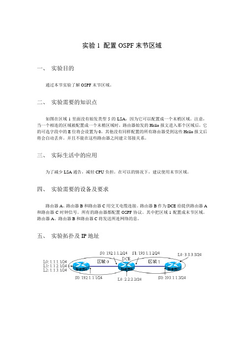
四、实验需要的设备及要求路由器A、路由器B和路由器C用交叉电缆连接。
路由器B作为DCE给提供路由器A 和路由器C时钟信号。
所有的路由器都配置OSPF协议。
其中把区域1配置成末节区域。
路由器A、路由器B和路由器C将发送所连网络的息。
五、实验拓扑及IP地址六、实验步骤1、给路由器分别命名主机名。
例如:路由器A:RouterA。
定义进入特权模式的密码为:cisco。
在全局模式下使用指令的关键字:hostname nameenable password2、根据拓扑图配置接口IP地址。
在全局模式下使用指令的关键字:interface interface在接口模式下使用指令的关键字:ip address ip-address mask3、在DCE端配置时钟。
在接口模式下使用指令的关键字:clock rate clock。
4、分别在3台路由器上运行ospf,并做通告。
在全局模式下使用指令的关键字:router ospf process-id在协议模式下使用指令的关键字:network address wildcard-mask area area-id5、分别在路由器B和路由器C配置ospf stub 区域在协议模式下使用指令的关键字:area area-id stub6、在路由器A上把环回口重分布到ospf中在协议模式下使用指令的关键字:redistribute connect subnets修改路由器B和C的环回口ospf的类型。
ciscoOSPF配置
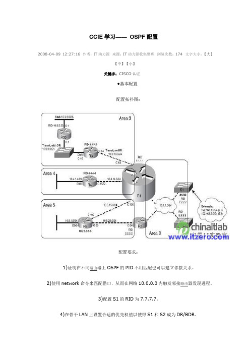
CCIE 学习—— OSPF 配置2008-04-09 12:27:16 作者:IT 动力源 来源:IT 动力源收集整理 浏览次数:174 文字大小:【大】【中】【小】关键字:CISCO 认证●基本配置 配置拓扑图:配置要求:1)证明在不同路由器上OSPF 的PID 不用匹配也可以建立邻接关系。
2)使用network 命令来匹配借口,从而在网络10.0.0.0内触发邻接路由器发现进程。
3)配置S1的RID 为7.7.7.7。
4)在骨干LAN 上设置合适的优先权值以使得S1和S2成为DR/BDR 。
5)在骨干LAN上配置dead间隔为最小(1秒),它是hello间隔的4倍,所以hello间隔为250毫秒。
6)配置区域3为完全NSSA区域,区域4为完全桩区域,区域5为桩区域。
具体配置:1)R1的配置:interface FastEthernet0/0ip address 10.1.1.1 255.255.255.0ip ospf dead-interval minimal hello-multiplier 4!router ospf 1area 3 nssa no-summaryarea 4 stub no-summaryarea 5 stubnetwork 10.1.0.0 0.0.255.255 area 0network 10.3.0.0 0.0.255.255 area 3network 10.4.0.0 0.0.255.255 area 4network 10.5.0.0 0.0.255.255 area 52)R2的配置:interface FastEthernet0/0ip address 10.1.1.2 255.255.255.0ip ospf dead-interval minimal hello-multiplier 4!router ospf 2area 5 stubnetwork 10.1.0.0 0.0.255.255 area 0network 10.5.25.2 0.0.0.0 area 53)R3的配置:router ospf 1area 3 nssa no-summarynetwork 10.0.0.0 0.255.255.255 area 34)R4的配置:router ospf 1area 4 stub no-summarynetwork 10.0.0.0 0.255.255.255 area 45)S1的配置:interface Vlan1ip address 10.1.1.3 255.255.255.0ip ospf dead-interval minimal hello-multiplier 4ip ospf priority 255!router ospf 1router-id 7.7.7.7network 10.1.0.0 0.0.255.255 area 06)S2的配置:interface Vlan1ip address 10.1.1.4 255.255.255.0ip ospf dead-interval minimal hello-multiplier 4ip ospf priority 254!router ospf 1network 10.0.0.0 0.255.255.255 area 0●OSPF的开销以及怎样重启OSPF进程IOS确定OSPF接口开销的方法:1)使用neighbor neighbor cost value命令对每台邻接路由器设置开销(对于允许使用neighbor命令的网络类型)。
实验9-3OSPF多区域配置
实验9-3OSPF多区域配置实验9-3 OSPF多区域配置一、原理概述在OSPF单区域中,每台路由器都需要收集其他所有路由器的链路状态信息,如果网络规模不断扩大,链路状态信息也会随之不断增多,这将使得单台路由器上链路状态数据库非常庞大,导致路由器负担加重,也不便于维护管理。
为了解决上述问题,OSPF协议可以将整个自治系统划分为不同的区域(Area),就像一个国家的国土面积很大时,会把整个国家划分为不同的省份来管理一样。
链路状态信息只在区域内部泛洪,区域之间传递的只是路由条目而非链路状态信息,因此大大减小了路由器的负担。
当一台路由器属于不同区域时称它为区域边界路由器(Area Border Router,ABR),负责传递区域间路由信息。
区域间的路由信息传递类似距离矢量算法,为了防止区域间产生环路,所有非骨干区域之间的路由信息必须经过骨干区域,也就是说非骨干区域必须和骨干区域相连,且非骨干区域之间不能直接进行路由信息交互。
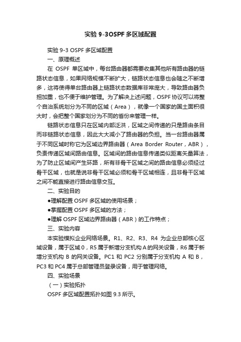
二、实验目的●理解配置OSPF多区域的使用场景;●掌握配置OSPF多区域的方法;●理解OSPF区域边界路由器(ABR)的工作特点;三、实验内容本实验模拟企业网络场景。
R1、R2、R3、R4为企业总部核心区域设备,属于区域0,R5属于新增分支机构A的网关设备,R6属于新增分支机构B的网关设备。
PC1和PC2分别属于分支机构A和B,PC3和PC4属于总部管理员登录设备,用于管理网络。
四、实验场景(一)实验拓扑OSPF多区域配置拓扑如图9.3所示。
图9.3 OSPF多区域配置拓扑(二)实验编址实验编址见表9-3表9-3 实验编址五、实验过程任务一基本自己置根据实验编址表进行相应的基本配置,并使用ping命令检测各直连链路的连通性。
ping 10.0.15.5(详细记录操操作过程及回显结果)测试通过,其余直连网段的连通性测试省略。
任务二配置骨干区域路由器在公司总部路由器R1、R2、R3、R4上创建OSPF进程,并在骨干区域0视图下通告总部各网段。
思科路由协议配置OSPF多区域[整理]
![思科路由协议配置OSPF多区域[整理]](https://img.taocdn.com/s3/m/36b3706503768e9951e79b89680203d8ce2f6a85.png)
思科路由协议配置OSPF多区域多区域的OSPFOSPF的区域类型:骨干区域:是OSPF网络的核心,负责连接所有的非骨干区域,区域之间的通讯必须通过骨干区域才能完成,也就是说在OSPF的多区域网络中必须存在骨干区域。
骨干区域的编号为0,area 0 就是骨干区域。
非骨干区域:区域编号为非0数值的OSPF区域。
OSPF的通讯类型:域内通讯量:区域内部网络之间的互相通讯。
域间通讯量:区域之间网络之间的互相通讯。
外部通讯量:OSPF网络与非OSPF网络之间的通讯。
OSPF路由器的类型:IR 域内路由器ABR 区域边界路由器BR 骨干路由器ASBR 自治系统边界路由器OSPF多区域网络中的LSA类型:LSA1:是由每台OSPF路由器产生,始发本机接口所连接链路的信息。
LSA1只在区域内部进行泛洪,可以实现域内的路由通讯。
LSA2:在多路访问型的网络中出现,由DR产生,发送给DRother的汇总后的LSA更新。
地址使用224.0.0.6,只在区域内部泛洪,实现的也是域内通讯。
LSA3:是由ABR域间路由器始发,泛洪到一个区域其所能到达的其他区域的路由信息。
实现域间路由信息的传递,ABR要宣告给它所连接的所有区域,最终实现域间的通讯。
LSA4:是由ABR始发,宣告到一个区域,宣告ASBR的位置信息。
告诉内部去往OSPF外部出口的路由信息。
LSA5:是由ASBR自治系统边界路由器产生,描述其所能到达的OSPF 外部路由信息,该更新将在整个OSPF自治系统中泛洪。
LSA7:NSSA中特有的外部路由更新。
为了实现对NSSA区域的优化,优化掉第4、5种类型的更新,又不会影响到其所连接的外部路由信息,在NSSA区域内部使用LSA7,来通告其所连接的外部路由信息,当LSA7经过ABR区域边界路由器时,会被转化成LSA5,因为对于其他区域来讲,外部路由就是LSA5。
ospf的路由类型:C 直连路由R rip路由D eigrp的内部路由D EX eigrp的外部路由O ospf的域内路由O IA ospf的域间路由O E2 ospf的2类外部路由O E1 ospf的1类外部路由O*IA OSPF的默认路由O N1 OSPF的NSSA区域的1类外部路由O N2 OSPF的NSSA区域的2类外部路由路由重分发,使rip、eigrp和ospf进行路由信息交换rip到ospfr1(config)#router ospf 10r1(config-router)#redistribute rip metric 20 subnetseigrp到ospfr7(config)#router ospf 10r7(config-router)#redistribute eigrp 10 metric-type 1 metric 30 subnetsospf 到 ripr1(config)#router ripr1(config-router)#redistribute ospf 10 metric 2ospf 到 eigrpr7(config)#router eigrp 10r7(config-router)#redistribute ospf 10 metric 1000 100 255 1 1500r4#show ip ospf database //查看ospf的LSDB末梢区域的配置ABRr2(config)#router ospf 10r2(config-router)#area 1 stubIRr4(config)#router ospf 10r4(config-router)#area 1 stubr5(config)#router ospf 10r5(config-router)#area 1 stub在末梢区域的基础上配置完全末梢区域在ABR上配置r2(config)#router ospf 10r2(config-router)#area 1 stub no-summary配置NSSA区域ABRr3(config)#router ospf 10r3(config-router)#area 2 nssar3(config-router)#area 2 nssa default-information-originater3(config-router)#area 2 nssa no-summary //优化掉LSA3IRr6(config)#router ospf 10r6(config-router)#area 2 nssaASBRr7(config)#router ospf 10r7(config-router)#area 2 nssaOSPF的外部路由r1(config-if)#int s0/0r1(config-if)#ip ospf cost 5 //定义OSPF的接口链路度量值r1(config-if)#int s0/1r1(config-if)#ip ospf cost 30r1(config-if)#router ospf 10r1(config-router)#network 0.0.0.0 0.0.0.0 area 0r2(config)#int s0/0r2(config-if)#ip add 192.168.11.2 255.255.255.0r2(config-if)#no shutdownr2(config-if)#ip ospf 10 area 0 //将该接口宣告到ospf 10 的区域0r2(config-if)#ip ospf cost 5将RIP充分发到OSPF,选择1类外部路由r2(config)#router ospf 10r2(config-router)#redistribute rip metric-type 1 metric 20 subnetsr2(config-router)#exitr3(config)#router ospf 10r3(config-router)#redistribute rip metric-type 1 metric 10 subnets选择2类外部路由r2(config)#router ospf 10r2(config-router)#no redistribute rip metric-type 1 metric 20 subnetsr2(config-router)#redistribute rip metric 20 subnetsr3(config)#router ospf 10r3(config-router)#no redistribute rip metric-type 1 metric 10 subnetsr3(config-router)#redistribute rip metric 10 subnetsr1#clear ip ospf process //重启下OSPF进程在OSPF多区域网络中必须存在骨干区域,区域0,因为所有的域间通讯必须要通过骨干区域。
思科OSPFv3配置实验案例分析
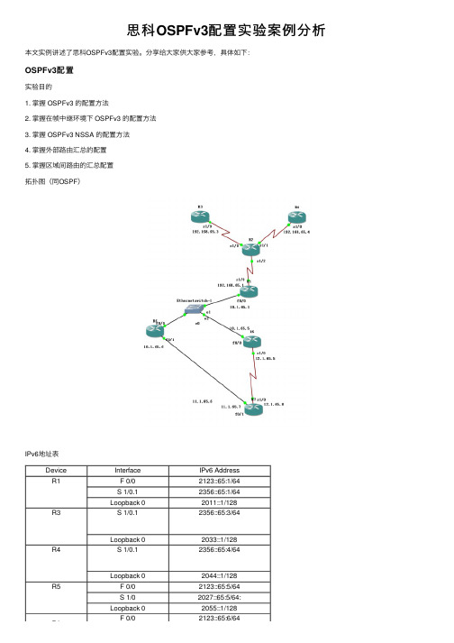
思科OSPFv3配置实验案例分析本⽂实例讲述了思科OSPFv3配置实验。
分享给⼤家供⼤家参考,具体如下:OSPFv3配置实验⽬的1. 掌握 OSPFv3 的配置⽅法2. 掌握在帧中继环境下 OSPFv3 的配置⽅法3. 掌握 OSPFv3 NSSA 的配置⽅法4. 掌握外部路由汇总的配置5. 掌握区域间路由的汇总配置拓扑图(同OSPF)IPv6地址表Device Interface IPv6 AddressR1 F 0/02123::65:1/64S 1/0.12356::65:1/64Loopback 02011::1/128R3S 1/0.12356::65:3/64Loopback 02033::1/128R4S 1/0.12356::65:4/64Loopback 02044::1/128R5 F 0/02123::65:5/64S 1/02027::65:5/64:Loopback 02055::1/128F 0/02123::65:6/64R6R6F 0/02123::65:6/64 Loopback 02066::1/128R7S 1/02027::65:7/64: Loopback 02077::1/128Device Interface IPv6 Address帧中继R2配置与ospfv2相同。
1.完成接⼝ IPv6 地址的配置,注意不要忘记配置 loopback0:R1(config)#ipv6 unicast-routing ―――全局打开 IPv6 路由功能R1config)#interface loopback 0R1(config-if)#ipv6 enableR1(config-if)#ipv6 address 2011::1/128―――配置 loopback0 接⼝地址R1(config-if)#int f 0/0R1(config-if)#ipv6 enableR1(config-if)# ipv6 address 2123::65:1/64R1(config-if)#no shutR1(config-if)#int s 1/0R1(config-if)#ipv6 enableR1(config-if)# encapsulation frame-relayR1(config-if)#no shutR1(config)#interface serial 1/0.1 multipointR1(config-subif)#ipv6 address 2356::65:1/64R1(config-subif)#frame-relay map ipv6 2356::65:3 103 broadcastR1(config-subif)#frame-relay map ipv6 2356::65:4 104 broadcastR1(config-subif)#frame-relay map ipv6 2356::65:1 104 broadcastR1(config-subif)#frame-relay map ipv6 FE80::C804:1CFF:FE48:8 104 broadcastR1(config-subif)#frame-relay map ipv6 FE80::C803:1CFF:FE48:8 103 broadcastR3(config)#ipv6 unicast-routingR3(config)#interface loopback 0R3(config-if)#ipv6 address 2033::1/128R3(config-if)#int s 1/0R3(config-if)#ipv6 enableR3(config-if)# encapsulation frame-relayR3(config-if)#no shutdownR3(config)#interface serial 1/0.1 multipointR3(config-subif)#ipv6 address 2356::65:3/64R3(config-subif)#frame-relay map ipv6 2356::65:1 301 broadcast (R4⽤401)R3(config-subif)#frame-relay map ipv6 2356::65:4 301 broadcast (R4⽤401)R3(config-subif)#frame-relay map ipv6 2356::65:3 301 broadcast (R4⽤401)R3(config-subif)#frame-relay map ipv6 FE80::C804:1CFF:FE48:8 304 broadcast(R4⽤C803,403)R3(config-subif)#frame-relay map ipv6 FE80::C801:1CFF:FE48:8 301 broadcast (R4⽤401)试R1上ping通 R3.R4⽤show frame-relay pvc命令查看,帧中继配置完成2. 按实验拓扑图标识的区域,完成 OSPFv3 的基本配置。
思科路由器设置OSPF

思科路由器设置OSPF推荐文章路由器设置端口映射方法是什么热度:双路由器时设置连接方法和单路由器一样吗热度:路由器UPNP是什么怎么设置热度:Linksys无线路由器怎么样设置热度:怎么设置cisco思科无线ap 热度:OSPF也称为接口状态路由协议,OSPF路由协议是一种典型的链路状态(Link-state)的路由协议,一般用于同一个路由域内有不少用户不知道cisco怎么设置ospf?店铺为大家分享了具体操作方法,供大家参考!思科路由器设置OSPF命令参考以下步骤:router(config)#router ospf 1 启动OSPF路由进程router(config-router)#router-id 1.1.1.1 配置Router IDrouter(config-router)#network 1.0.0.0 0.255.255.255 area 0 指定OSPF协议运行的接口和所在的区域多区域OSPF:router(config)#router ospf 1router(config-router)#router-id 1.1.1.1router(config-router)#network 1.0.0.0 0.255.255.255 area 0 router(config-router)#network 2.0.0.0 0.255.255.255 area 1 末梢区域:router(config)#area1 stub完全末梢区域:router(config)#area1 stub no-summary路由重分发配置:router ripredistribute ospf 10 metric 10router ospf 10redistribute rip metric 10 subnetsNSSA区域配置:router(config)#area1 nssa虚链路配置:router(config)#area 100 virtual-link 1.1.1.1对方RID 店铺分享了cisco设置ospf的解决方法,希望大家喜欢。
OSPF实验4OSPF多区域配置
OSPF实验四OSPF多区域配置
一、实验目的
配置OSPF的多区域并进行路由汇总。
应用场景:作为使用最为广泛的动态路由协议,OSPF的使用一般都要划分区域并在ABR上针对路由进行汇总。
二、实验设备
四台Cisco 7206 VXR 中由器、IOS版本V ersion 12.3(5)。
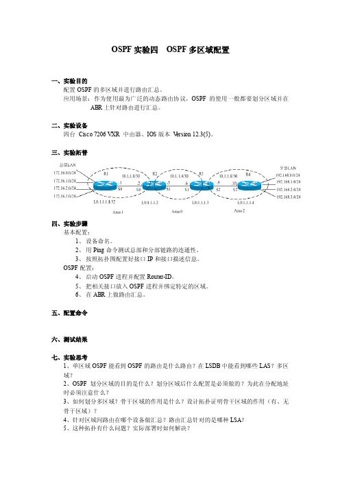
三、实验拓普
四、实验步骤
基本配置:
1、设备命名。
2、用Ping命令测试总部和分部链路的连通性。
3、按照拓扑图配置好接口IP和接口描述信息。
OSPF配置:
4、启动OSPF进程并配置Router-ID。
5、把相关接口放入OSPF进程并绑定特定的区域。
6、在ABR上做路由汇总。
五、配置命令
六、测试结果
七、实验思考
1、单区域OSPF能看到OSPF的路由是什么路由?在LSDB中能看到哪些LAS?多区
域?
2、OSPF划分区域的目的是什么?划分区域后什么配置是必须做的?为此在分配地址
时必须注意什么?
3、如何划分多区域?骨干区域的作用是什么?设计拓扑证明骨干区域的作用(有、无
骨干区域)?
4、针对区域间路由在哪个设备做汇总?路由汇总针对的是哪种LSA?
5、这种拓扑有什么问题?实际部署时如何解决?
6、不希望其他区域看到本区域的设备及链路IP,如何实现?
7、LSA1、LSA2、LSA3分别是哪个设备产生的?作用是什么?各自的关系是什么?查看LSA具体的内容?并尝试读解。
CISCO多区域OSPF讲解

R2#show ip route ospf
以上输出表明R2 对R1 的四条环回接口的路由汇总后,会产生 一条指向Null0 的路由;同时收到经路由器R3 汇总的路由, 因为是重分布进来的外部路由,所以路由代码为“O E2”。
R3#show ip route ospf
以上输出表明R3 对四条环回接口的RIP 路由汇总后,会产生一 条指向Null0 的路由;同时收到经路由器R2 汇总的路由,由于 是区域间路由汇总,所以路由代码为“O IA”。
OSPF 多区域的拓扑结构有如下的优势:
1. 降低SPF 计算频率 2. 减小路由表 3. 降低了通告LSA 的开销 4. 将不稳定限制在特定的区域
OSPF 路由器类型
1. 内部路由器:OSPF 路由器上所有直连的链路都处于同一个区域; 2. 主干路由器:具有连接区域0 接口的路由器; 3. 区域边界路由器(ABR):路由器与多个区域相连; 4. 自治系统边界路由器(ASBR):与AS 外部的路由器相连并互相交换 路由信息;
多区域OSPF
高级多区域OSPF技术
多区域OSPF
在一个大型OSPF 网络中,SPF 算法的反复计算,庞大的 路由表和拓扑表的维护以及LSA的泛洪等都会占用路由器的资源, 因而会降低路由器的运行效率。 OSPF 协议可以利用区域的概念来减小这些不利的影响。因 为在一个区域内的路由器将不需要了解它们所在区域外的拓扑细 节。
关键实验步骤
配置时采用环回接口尽量靠近区域0 的原则。路由器R4 的环回 接口不在OSPF 进程中通告,通过重分布的方法进入OSPF 网络。
路由器R1 R1(config)#router ospf 1 R1(config-router)#router-id 1.1.1.1 R1(config-router)#network 1.1.1.0 255.255.255.0 area 1 R1(config-router)#network 192.168.12.0 255.255.255.0 area 1
- 1、下载文档前请自行甄别文档内容的完整性,平台不提供额外的编辑、内容补充、找答案等附加服务。
- 2、"仅部分预览"的文档,不可在线预览部分如存在完整性等问题,可反馈申请退款(可完整预览的文档不适用该条件!)。
- 3、如文档侵犯您的权益,请联系客服反馈,我们会尽快为您处理(人工客服工作时间:9:00-18:30)。
! router ospf 1 router-id 0.0.0.4 !
R5
! interface Ethernet0/1 ip address 192.168.45.5 255.255.255.0 ip ospf network point-to-point ip ospf 1 area 99 end
背景信息
OSPF 链路状态路由协议使用区域的概念,区域是 OSPF 域内的子域。区域内的路由器保留该区域 的完整拓扑信息。默认情况下,接口只能属于一个 OSPF 区域。这不仅会导致网络中的次优路由问 题,而且在网络设计不正确时还会导致其他问题。 在接口上配置多区域邻接时,OSPF 发言者会在该链路上建立多个邻接关系 (ADJ)。多区域接口是 一种用于形成 ADJ 的点对点逻辑接口。本文档描述了一个可以使用多区域 OSPF ADJ 解决问题并 满足网络要求的场景。
! ip route 10.1.1.1 255.255.255.255 192.168.12.1
! router ospf 1 router-id 0.0.0.2 redistribute static metric-type 1 subnets !
R3
! interface Ethernet0/0 ip address 192.168.34.3 255.255.255.0 ip ospf network point-to-point ip ospf 1 area 99 end
! router ospf 1 router-id 0.0.0.3 !
R4
! interface Ethernet0/0 ip address 192.168.34.4 255.255.255.0 ip ospf network point-to-point ip ospf 1 area 99 end
! interface Loopback0 ip address 10.5.5.5 255.255.255.255 end
! router ospf 1 router-id 0.0.0.5 !
默认行为
本部分介绍在完成上文配置时路由器的默认行为。
以下是从 R5 到 10.1.1.1 的跟踪结果。请注意,流量通过 R2,而不是 R3:
! ip route 0.0.0.0 0.0.0.0 192.168.12.2 !
R2
! interface Ethernet0/0 ip address 192.168.12.2 255.255.255.0 end
! interface Ethernet0/1 ip address 192.168.23.2 255.255.255.0 ip ospf network point-to-point ip ospf 1 area 0 end
! interface Ethernet0/1 ip address 192.168.45.4 255.255.255.0 ip ospf network point-to-point ip ospf 1 area 99 end
! interface Ethernet0/2 ip address 192.168.24.4 255.255.255.0 ip ospf network point-to-point ip ospf 1 area 99 end
采用多区域邻接配置的 OSPF 示例
目录
简介 先决条件 要求 使用的组件 背景信息 配置 网络图 初始配置 R1 R2 R3 R4 R5 默认行为 多区域邻接配置 验证 故障排除
简介
本文档介绍如何为多区域邻接配置开放最短路径优先 (OSPF) 链路状态路由协议。
先决条件
要求
Cisco 建议您了解以下主题:
q OSPF
q 多区域邻接 思科还建议在尝试本文档中描述的配置之前先满足以下要求:
q 必须在网络中预先配置 OSPF 链路状态路由协议。
q 只有两个 OSPF 发言者使用在其间 OSPF 多区域功能可正常工作的接口。多区域 OSPF 仅适 用于点对点网络类型。
使用的组件
本文档中的信息基于多区域 OSPF。 本文档中的信息都是基于特定实验室环境中的设备编写的。本文档中使用的所有设备最初均采用原 始(默认)配置。如果您使用的是真实网络,请确保您已经了解所有命令的潜在影响。
! interface Ethernet0/2 ip address 192.168.24.2 255.255.255.0 ip ospf network point-to-point ip ospf 1 area 99 end
! interface Loopback0 ip address 10.2.2.2 255.255.255.255 end
配置
网络图
此网络图中使用了网络/OSPF 域。系统要求从路由器 5 (R5) 到 R1 (10.1.1.1) 的流量都应当通过它进行路由,或者 R3 与 R4 之间的链路带宽
高于 R2 与 R4 之间的链路带宽。在这两种情况下,系统都要求流量从 R5 传递到 R1(10.1.1.1/32 前缀)时必须流经 R3。
! interface Ethernet0/1 ip address 192.168.23.3 255.255.255.0 ip ospf network point-to-point ip ospf 1 area 0 end
! interface Loopback0 ip address 10.3.3.3 255.255.255.255 end
初始配置
本部分介绍 R1 到 R5 的初始配置。
R1
! interface Ethernet0/0 ip address 192.168.12.1 255.255.255.0 end
! interface Loopback0 ip address 10.1.1.1 255.255.255.255 end