lighttools_软件-LED反光杯设计
LightTools 小面反光杯的设计

主讲:赵伟星 weixing@
Day 1 - 1
LightTools 建模实例 拉伸反射器
拉伸反射器 Extruded Reflector
抛物面焦距为 7mm 直径大约为 45mm
Day 1 - 2
LightTools 建模实例 拉伸反射器
LightTools 的环形阵列CircArray
3 选择虚拟球,再选择修剪单体 SHIFT + Click
4 使用环形阵列命令按钮 - 基准位置 ������ XYZ 0,0,0 - 沿着基准线方向的实体数量 1 - 沿着基准线方向的第一个复制坐标 XYZ 0,0,0 - 沿着正交方向的数量 18 = 360/20
Day 1 - 10
LightTools 阵列反射器
将修剪后的单体生成阵列反射器 使用环形阵列360度生成反射器 原始的单体不是最终物体的部分 阵列物体都是独立的实体 需要使用合集Union 使之成为整体
Day 1 - 11
LightTools 的环形阵列CircArray
LT环形阵列的命令格式为: CircArray XYZ 0,0,0 1 XYZ 10,0,0 8列CircArray
5 删除原始的修剪单体
6 删除所有的虚拟球体
Day 1 - 15
LightTools 的环形阵列CircArray
7 全部选中,进行链接 Union
Day 1 - 16
LightTools 表面属性 Surface Properties
Day 1 - 6
LightTools 建模实例 拉伸反射器
添加NS光线,查看反射器反光效果
在车灯上的应用很多
小面越大,偏离抛物面越多
LightTools-照明设计解析软件
O P T I C A L R E S E A R C H ASSOCIATES 高峰
目录
1.引言
本文目录 结构
2.LightTools的组成模块
3.LightTools的应用领域
1.引言
LightTools是美国Optical Research Associates开发的真正意义上的照 明设计解析软件。内置3维CAD建模功能,在LightTools中可与任意的模块 进行组合,可自由设定反射、透射、散射、偏振光、薄膜等的光学特性。 可高精度、快速获得这些特性的照度分布、亮度分布、色度分布等计算结 果。LightTools依靠操作方便和丰富的设计功能模块,获得最佳的测试结 果,是一款卓越的照明设计工具。
2.LightTools的组成模块
★接收器设定 1.接收器(面、远场接收器) 2.表面的照度 3.亮度分布解析 4.光学系统整体的配光分布解析 5.滤光功能(面、波长、光路长度等) ★各种解析结果 1.2种亮度输出(空间亮度计,角度亮度计) 2.测试角度、范围的设定 3.散射图(光线和感光面的交点显示) 4.光栅图(伪彩表示) 5.线图 6.面图(3D阴影显示) 7.LumViewer(光栅、面、线同时显示) 8.CIE色度图输出 9.照度、角度强度分布的RGB输出 T功能(各光路的评价·解析、杂散光解析 11.光路追踪功能——光路的评价解析、杂散光解析
2.LightTools的组成模块
Solid Works Link Module
1.在Link的状态下,可以直接在LightTools中输入在Solid Works中制作的元 件和装配件。 2.在SolidWorks Link Module中设定的尺寸等参数可以直接在LightTools中编 辑。 3.与在LightTools中制作的其他元件相同,通过最优化功能能够自动修改在 LightTools中可编辑的SolidWorks模型的参数。
Light Tools软件介绍

LightTools 简介LightTools 是一个全新的具有光学精度的交互式三维实体建模软件体系,提供最现代化的手段直接描述光学系统中的光源、透镜、反射镜、分束器、衍射光学元件、棱镜、扫描转鼓、机械结构以及光路。
由于LightTools 把光学和机械元件集合在统一的体系下处理,并配有“放置”光源、发射光线的非顺序面光线追迹的强大功能,使它在系统初步设计、复杂系统设计规划、光机一体设计、杂光分析、照明系统设计分析、单位各部门间学术交流和数据交换、课题论证或产品推广等各环节中均可发挥重要的作用,成为人们理想的工具。
LightTools 简介美国Optical Research Associates (ORA®) 公司以研制国际领先的CODE V® 光学工程软件而著称于世。
1995年,该公司根据用户需求和计算机技术的发展,隆重推出最新产品—光学系统建模软件LightTools,马上得到各国用户的欢迎和好评,并获得国际大奖。
1997年,ORA 又研制成功与LightTools 主体程序配套使用的Illumination 模块,圆满地解决了照明系统的计算机辅助设计问题。
其中的主要功能简单介绍如下:系统建模提供多种展现系统光机模型的方式和人机交互的手段。
使用者可直接在系统的二维、三维线框图或三维实体模型图上进行各种操作。
方便易用的图形交互式建模和修改功能包括元件或元件组的放置、移动、旋转、复制和缩放。
操作时既可用鼠标以实时观察修改造成的效果,也可用键盘以输入准确的数据。
透镜、反射镜和棱镜等光学元件及各种机械件可以极快地以图形方式“画入”系统。
系统数据可以用表格和元件详情对话框的形式列出和修改。
所有上述各种输入方式同时并存,可交替使用。
光机一体化设计光学和机械元件的形状的描述是通过对软件提供的一组尺寸可变的基本实体模型做布尔运算(与、或、异等等)实现的。
这些光学或机械部件的形状虽然可能非常复杂,但均可以在软件中得到精确的展现和描绘,并以光学精度进行光线追迹。
LightTools功能与应用简介
– 可將 3D Texture 轉換成實體形狀 – 具有修復功能
8
4
材料特性
• LightTools 提供各式的材料特性
– 玻璃(Schott, Hoya, Ohara, China…) – 塑膠(PMMA, PC, PS…) – 特別材質(AIR, Silicon…) – 自訂材料
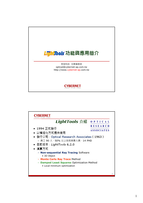
功能與應用簡介
思渤科技 光學業務部 optical@
LightTools 介紹
• 1994 正式發行 • 以模組化方式提供使用 • 發行公司:Optical Research Associates(1963)
Epoxy Package
分析結果 OK
資料輸出
NS Ray Parametric control
最佳化
最佳化 NG
設計過程
7
3D 實體模型
• 以實體物件來表達
– 所有特性都可作控制(形狀、材料、表面) – 材質:折射率、吸收率、體散射、偏振 – 表面:穿透反射吸收、散射、塗膜、偏振、Fresnel loss
• 可進行
– 布林運算 – 移動、複製、尺寸和旋轉 – 膠合、沈浸
• 是非常好用的分析工具,尤其是雜散光的分析
24
12
情境模擬 Photorealistic Rendering
• 照明模組的功能 • 允許使用者建構如照片般真實的影像
– 可模擬模型未發光與發光時的情景
環境光
情境光
25
最佳化(優化)
• 最佳化就是根據標準或誤差函數,透過自動計算來改善系 統性能
• 最佳化三大基本組成:
– 誤差函數 Merit Function (Error Function): • 系統的目標函數,是單一的數值。若該數值為 0 表示已經達成目標
LightTools 光学模拟软件说明书
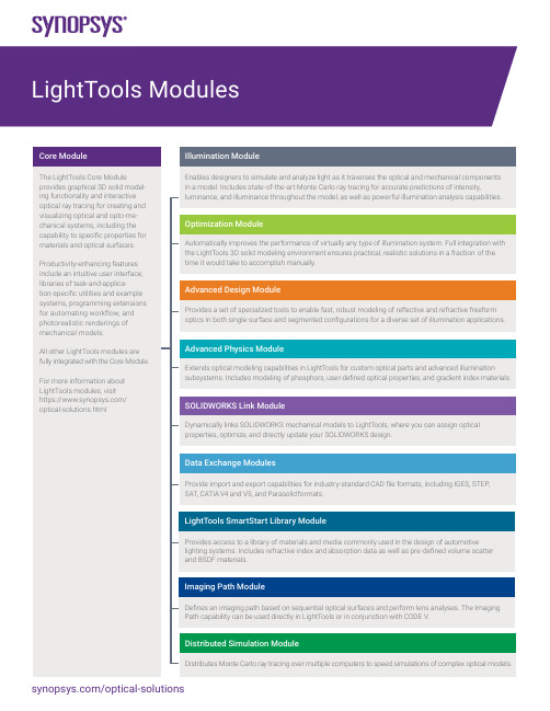
Core ModuleGeometry Creation and Editing• Lens primitives (rectangular or circular apertures)• Spline sweep and patch surfaces• Polyline sweeps and extrusions• Conic trough and revolved reflectors• Cylinders, blocks, spheres, toroids, and skinned solids• Union, intersection, subtraction boolean operations• Object trim operation• Move, rotate, scale, align• Copy, rectangular, and circular pattern copy• Multiple and partial immersion and cementing for solid objects• Pickups for parametric modeling• Grouping of model entitiesOptical Properties• Specular reflection/transmission/TIR with Fresnel losses• Diffuse transmission/reflection• Scatter models: mixed diffuse, narrow angle, and angle of incidence (AOI)• Volume scattering (Mie, user defined)• Scattering aim regions• User-defined coatings• Probabilistic ray splitting and importance sampling• Constant or varying optical density or transmittance vs. length• Index of refraction (constant, interpolated, standard dispersion formulas)• Surface patterns of 2D or 3D elements• Photorealistic rendering (Illumination Module needed for lit appearance)User Interface and Other Features• ActiveX interface for macro programming in MS Excel, VB, VC++, Matlab, Mathematica, and others • OpenGL-rendered graphics• Tabbed windows and editable spreadsheets• Multiple design views and navigation windows• Point-and-click, copy-and-paste, moving and resizing of windows• Extensive help featuresPoint-and-Shoot Ray Tracing• Parallel, diverging, or converging sets of rays• Individual rays, 2D ray fans, 3D ray grids• Sequential and non-sequential ray propagationLibraries• LED sources• Display films• Application and feature examplesIllumination ModulePowerful illumination analysis capabilities, such as photorealistic renderings that show the luminance effects of light sources in the model, simulate real-world conditions and reduce the need for physical prototypes.Illumination Analysis• Photorealistic Rendering• Photometric or radiometric analysis using forward and backward ray tracing• Illuminance, luminance, luminous intensity• Line charts, raster, contour, and surface charts• Colorimetric analysis: 1931 and 1976 CIE coordinates, correlated color temperature• RGB output display, CIE chromaticity chart• Post-processing of output data• Receiver data filtering using over a dozen filter types• Encircled and ensquared energy• Spectral power distribution• Multi-CPU processingSources and Receivers• Point sources• Volume and surface emitters (spheres, cylinders, blocks, toroids)• User-defined spatial, volume, and angular distributions• Source emittance aim regions• Spectral distributions: Blackbody, Gaussian, continuous, discrete, and user defined• Angular and spatial importance sampling• Ray data sources and Radiant Imaging source model support• Surface and far field receivers• Angular and spatial luminance meters• Receiver aperture sub-samplingOptimization ModuleThe Optimization Module gives designers tremendous flexibility to choose from hundreds of system parameters to designate as variables, constraints, and performance criteria in order to achieve the desired system performance.Illumination Optimization• Optimize illumination uniformity and/or flux on a receiver• Match target illumination distributions• Collimate and focus merit functions for non-sequential rays• Lagrange constraint handling• User-defined variables, constraints, and performance criteria• Vary any floating point model parameter• User-defined combinations of parameters• Bounded and unbounded variables• Backlight pattern optimization utility• Parameter sensitivity utility• Point-and-shoot ray merit functionsAdvanced Design ModuleThe Advanced Design Module leverages proprietary algorithms from Synopsys’ LucidShape products that automatically calculate and construct optical geometries based on user-defined illuminance and intensity patterns. This unique, functional approach gives designers the freedom to focus on overall design objectives rather than the implementation details of complex optical components.• Freeform Design features for modeling freeform reflective and refractive surfaces that are automatically shaped to form the resulting light pattern.• MacroFocal Reflector tool for designing multi-surface segmented reflectors, with different spreads for each facet.• Procedural Rectangle Lens tool for designing surfaces with pillowed optical arrays.• LED Lens tool for creating various types of freeform LED collimator lenses.Advanced Physics Module• Designers can take advantage of programming extensions to develop custom optical parts and advanced illumination subsystems using:• Phosphor particle modeling (single and multiple)• Gradient Index (GRIN) materials - used in copiers, scanners, and fiber optic telecommunication systems.• User-defined optical properties (UDOPs) - such as proprietary polarization components, scatterers, coatings, and other specialty optical materials.• Birefringent (uniaxial) materials - used in advanced applications such as AR/VR headsets and biomedical instruments.The results for UDOPs and birefringent materials can be packaged into a portable format and exchanged with your project team, customers, suppliers, and subcontractors.SOLIDWORKS Link ModuleThe SOLIDWORKS Link Module enables you to link SOLIDWORKS 3D opto-mechanical models to LightTools, where you can assign optical properties and use the Optimization Module to optimize your design. This module provides complete parametric interoperability between LightTools models and SOLIDWORKS.Data Exchange ModulesSupporting features for the Data Exchange Modules include the ability to group and simplify imported geometry and perform geometry repairs to maintain CAD model integrity and improve ray trace speed.Translators• SAT version 1.0 through 7.0• STEP AP 203 and AP 214• IGES version 5.3, including surfaces and solids• Parasolid• CATIA V4 and V5 (import and export)• Grouping and simplification of imported surfaces• Geometry repairLightTools SmartStart Library ModuleProvides access to a library of materials and media commonly used in the design of automotive lighting systems. Includes refractive index and absorption data as well as pre-defined volume scatter and BSDF materials.Imaging Path Module• Sequential ray tracing• Paraxial solves• Image path view• Spot diagram and transverse aberration plotsDistributed Simulation ModuleThe Distributed Simulation Module allows you to distribute Monte Carlo ray tracing over multiple computers to speed simulations of complex optical models.©2022 Synopsys, Inc. All rights reserved. Synopsys is a trademark of Synopsys, Inc. in the United States and other countries. A list of Synopsys trademarks isavailable at /copyright.html . All other names mentioned herein are trademarks or registered trademarks of their respective owners.。
LightTools 在LED背光设计中的应用-北大深圳研究院

LightTools在LED背光设计中的应用金鹏1,叶浩21.北京大学深圳研究生院2.莎益博设计系统商贸(上海)有限公司摘要:在背光的设计中,一个主要的目标和挑战是保证在垂直于光的传播方向上提升光的利用效率。
在背光模组中,是通过导光板来实现这一过程的,设计的关键就在于找到一种合理的网点分布以获得均匀的亮度分布。
利用光学软件模拟可以自动优化这一过程从而简化设计流程。
关键词:背光模组;导光板;LightTools;自动优化中图分类号:文献标识码:The application of LightTools in LED backlights design(Peng Jin; Shenzhen Graduate School, Peking UniversityHao Ye; Cybernet CAE Systems(Shanghai)Co., Ltd)Abstract:In the backlight design, a major goal and challenge is to ensure that light efficiency has been enhanced in the direction that is perpendicular to the propagation direction of light. In the backlight module, this process is achieved through the light guide plates. the key of the design is to find a reasonable distribution of nodes to obtain uniform brightness distribution. Optical software can automatically optimize and simplify this design processKeywords:backlight module; light guide plate; LightTools; automatic optimization1 引言近年来液晶显示器(LCD)获得迅速发展,并逐渐以主流产品出现在显示市场,相应的,作为LCD显示的核心技术之一的背光源技术也得到了很大的发展【1】。
lighttools光学模拟软件使用手册

光度學
光亮度 Luminance或Brightness lm/m2-sr=cd/m2 =nit
WRITTEN BY ADAMLEE
6
2014/7/9
輻射度學與光度學的轉換
一個candela發光強度的單位是定義為556nm的單色 光光源在一定方向發出每立體角1/683瓦特的輻射強 度 流明是均勻的點光源發出一個candela的發光強度的 光通量進入一個單位立體角
WRITTEN BY ADAMLEE
10
2014/7/9
關與Receiver
Receiver是這樣一種特殊的物體,它為系統提供了一個約 定,系統會統計接觸到這一物體的光線數據.這裡再一次強 調“光線”是空間中帶有能量,方向向量及其他光線追跡 所必須的參數的點而不是一條線.
當你的系統已經包含Receiver,並進行了足夠數量的 光線追跡後,系統便可以按照不同類型的Receiver來進行 不同方面的分析工作.
19
2014/7/9
Element panel
這個面板檔中包含八種類型的光學 元件,通過級連菜單選擇各分類命令. 由於LightTools提供了較為靈活的 定義方式,所以可以先不設置參數, 通過在3D窗口內點選的方式插入物 體.然後在System navigator中右鍵 單擊,修改該物體properties中的各 項參數設定
WRITTEN BY ADAMLEE
16
2014/7/9
Error window
在這個窗口內,顯示在程式運行過程當中所出 現的錯誤或警告信息.這些信息通常是必須要 引起注意併解決的.如果你的程式經常給出這 樣的信息而得不到解決的話,那麼模擬的準確 性就十分值得懷疑了.
WRITTEN BY ADAMLEE
LED背光的设计与优化(LightTools)
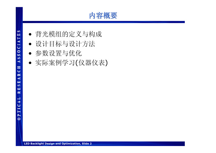
内容概要•背光模组的定义与构成•设计目标与设计方法•参数设置与优化•实际案例学习(仪器仪表)背光模组的定义•一般构成–导光板•通常其材料为塑料•注射成型或印刷式的网点(导光板下表面)–光源和反射罩•(典型光源CCFL and LED )–其他常用的光学元件扩散片(可提高均匀性)反射片•一些元件能否被使用取决于它的尺寸大小和成本以及其它要求Schematic of a typical backlight designLight source Light guideDiffuserReflectorAppliquéTransparency主要设计目标•在垂直光的传播方向上提升光的利用效率Light SourcePreferred direction of light extractionDirection of light propagationLight guideLight extraction from a light guide设计过程: 均匀性•光能量的传播是随导光板的长度变化的-出光的提取效率要随导光板的长度的增加而增加•改变光提取效率的方法:-改变网点密度,网点大小, 网点排布间距Distance from the sourceAvailable powerExtraction efficiencyUniform output背光网点设计•网点模型:印刷式的或注射成型的网点在背光设计中经常用到这两种网点来获得亮度均匀的背光•最佳的设计参数是优化后得到的网点密度分布Pattern Generator+CADIllumination SoftwareOutputOKUnacceptable优化过程通过不断反复调整网点参数进行优化,可以得到最终最佳的亮度与均匀性。
-可以通过做样品或软件模拟来完成光线追迹后输出模拟结果对比输出结果与初始要求网点参数设置计算新的网点更新模型完成OKNot OK网点参数的确定–为避免产生莫尔条纹,每个区域网点的密度是不一样的网点参数确定方法:–定义网点密度为二维网格值–定义网格值•网点的大小为变量•网点的数量和大小都为变量假设给定网点大小与形状通过计算在一个区域内变化网点的数量,得到想要的网点密度–网点密度的变化应该是缓慢而平滑的–人眼对突变是很敏感的,对渐变却不敏感变化网点数量的其他方法–分子动力学方法–多联骨牌法Mosaic Structure withObservableRectilinear Substructure Smooth Variation withObservableRectilinear SubstructureSmooth Variation withSinusoidal Shifts假设给定网点位置排布–经常用的排布一般为六角形通过计算在一个区域内变化网点的大小通过计算在一个区域内变化网点的大小,,得到想要的网点密度–出光的效率和网点排布的密度是成比例的Mosaic Structure using Hexagonal Pattern Smooth Variation using Hexagonal Pattern Smooth Variation using Rectilinear Pattern网点可以在位置的附近移动偏移网点可以在位置的附近移动偏移,,进行随机的变化, 但并不会重叠–也可以对网点的大小进行随机控制Dither X,Y=1,0Dither X,Y=0,1Dither X,Y=1,1Dither X,Y=0,0Dither X,Y=.2,.2Dither X,Y=.5,.5光线追迹与模拟评估此商业照明软件可以对背光进行设计模拟评估–运用蒙特卡罗随机光线追迹的方法来进行光度计算和模拟–模拟结果的精确度取决于光线追迹的数量和分辨率的高低高分辨率低精度低分辨率高精度高分辨率高精度--更多的光线--模拟评估可以使用优化函数进行模拟可以使用优化函数进行模拟,,比较输出结果与要求比较输出结果与要求,,进行评估-可使用优化函数限定统计噪声的最小值•当达到设计目标时可以中止优化函数•可增加光线的数目MF = ∑W i 2(V i -T i )2W i = Weight of i th MF item V i = Current Value of i th MF item T i = Target of i thMF itemLuminancewith 10,000 RaysLuminancewith1,000,000 RaysMF = ∑W i 2(V i + ∈i -T i )2MF = ∑W i 2(V i -T i )2 +Noise网点优化•BPO 通过改变网点的间距和大小来达到设计的要求•网点优化可以是2维的平面网点也可以是3维的网点•我们可以定义个接收面来接收并计算背光板表面的亮度和照度BPO 自动优化网点的过程•BPO 提供有效的优化网点的过程方法案例1: 印刷式导光板的网点优化在开始的时候使用均匀的印刷式网点进行优化得到合理的网点参数Small Source(e.g., LED)2D Display案例2: 注射成型网点的优化–网点大小相同,对排布的位置做优化处理来提高光的利用效率–这个例子是使用注射成型的网点进行优化LEDStartFinalTexture Density Output案例3: 两个LED, 非对称排布•使用注射成型的网点排布•两个LED–LED 采用非对称排布LEDsStartFinalTexture Density Output案例4: 两个LED, 对称排布•使用注射成型的网点排布•两个LED–LED 采用对称排布LEDsStartFinalTexture Density OutputSetupBitmap AppliquéSide ViewTop ViewLEDTextureAcrylic Light PipeBlue Filteron kph Appliqué•如下位图是作为优化的目标illuminance inthe blackregionsOptimization Results15 minutes2.33Ghz processor100,000 rays/iteration Iteration 1Iteration 2Iteration 3Iteration 4Iteration 5Iteration 6•模拟结果Illuminance Chart (1M rays) PhotoRealistic Rendering (100M rays)亮点边缘照明不足•需要新的目标区域设定全覆盖整个面积原有仪表盘结构新的仪表盘结构•最后的结果Photorealistic Rendering (100M rays)结论•网点的优化和模型设置及参数类型选择有紧密联系•介绍了用LightTools 进行设计和分析的一个汽车仪表盘背光的例子。