ALIGN T-REX 450L DOMINATOR组装介绍
新手必读教材,亚拓450组装到调试全套图文详细讲解
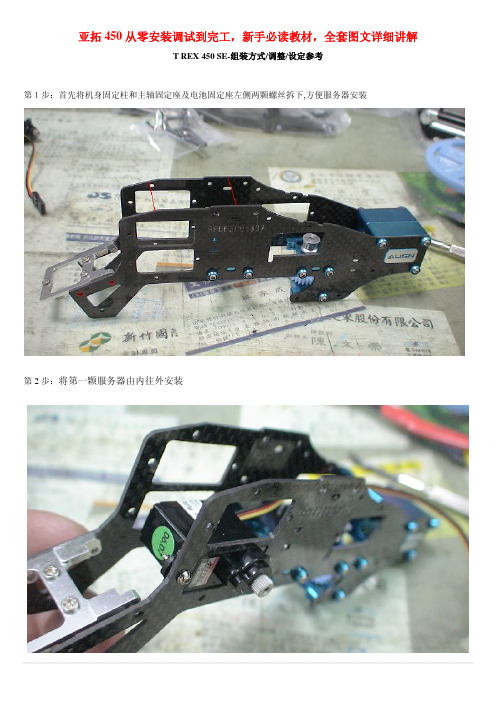
亚拓450从零安装调试到完工,新手必读教材,全套图文详细讲解T REX 450 SE-组装方式/调整/设定参考第1步:首先将机身固定柱和主轴固定座及电池固定座左侧两颗螺丝拆下,方便服务器安装第2步:将第一颗服务器由内往外安装第3步:同样的由内往外安装第二颗服务器,并将讯号线排列整齐用速线带固定,切记,1.速线带头在机身内侧2.在固定于册版的地方用透明胶带包覆两圈,防止组装时讯号线破损第4步:将伺服机讯号线由内侧版经沟槽穿往机身外侧第5步,将服务器的讯号线整理后,再用蛇管包覆第6步:将机身固定柱和主轴固定座及电池固定座左侧两颗螺丝装回原来位置记得要上螺丝胶喔第7步:将中间的侧版固定柱套入,并对准螺丝孔.将马达固定座装上下侧版第8步:1.利用马达固定座将上.下侧版组合2.将中侧版固定柱锁上螺丝第9步:将服务器讯号线穿过上.下侧版并将左侧三颗螺丝锁上第10步:右侧版先锁上1的螺丝,其它两颗先不锁第11步:将所需的马达同齿固定后,在将马达固定在马达坐上第12步:将马达线穿过机身底板和组装好的脚架,并将脚架固定第13步:将皮带穿过尾管(注意皮带的方向性)并将尾服务器座套入尾管,然后跟机身组合,并将垂直/水平/支撑架装上,调整皮带的松紧度后上紧尾管固定座的螺丝第14步:金属尾传动轮座组固定前,需确认与尾管固定座呈平行状态第15步:陀螺仪的整线后用蛇管包覆第16步:将陀螺仪用双面胶固定在尾管固定座上后,将包覆好的讯号线穿过上.下侧版后再将右侧版的两颗螺丝上紧(陀螺仪安装在尾固定座的下方,以防炸机时被副翼打到)第17步:先抓出尾服务器的中点,并将球头固定在服务器的摆臂上(上下两个圈是行程终点),并将服务器固定在尾伺服座上第18步:装好尾服务器时,套上连杆后,注意,这是重点1,尾舵控制组需在尾主轴中央2.调整尾服务器座让连杆跟尾管平行3.尾服务器摆臂球头需在中点4. 尾连杆和尾管尽量跟尾管呈平行以上确定后在固定尾伺服座螺丝第19步:1.将主轴上的连杆按说明书上的长度组装,并套上摆臂平衡杆先量好两边相等长度后套入平衡杆重垂在装上平衡翼2.将主轴和机身组合第20步:组合好后请注意大齿盘于机身的间隙,不能摩擦到机身或尾传动轮第21步:调整马达铜齿的高度并将铜齿固定螺丝上紧,调整马达与大齿盘的间隙后再将马达固定螺丝上紧第22步:1.用2mm钻尾将欲锁球头的摆臂扩孔2.将球头利用螺母固定在摆臂上3.将多余的摆臂去掉.以免摆动时干涉4.将服务器连杆依说明书长度组装好第23步:将组装好的摆臂套上服务器,先不上服务器螺丝,以便调整时需拆下,此时连杆都是呈垂直状态第24步:接收的整理1.用热缩套管或由机的油管将接收线的前端包覆,以防接收线和侧版接触而出现干扰现象,相信很多人有这个经验2.用1mm的泡棉将接受包覆并用透明胶带在包覆,以防日久泡棉脱落,这可以防止摔机后的碰撞以以多一层的防干扰的作用第25步:1.用双面胶将接收固定在底板2.将讯号线接上接收第26步:1.用打火机熏烤将热缩套管定型你要的角度2.在用热缩套管将整理的接收线固定在线管上第27步:将电子变速器的讯号线穿过脚架和底板之间并接上接收(马达线先不要接,以便遥控器设定和调机)-----------------------------------以上是机械及电子部件的安装--------------------------第28步:控的设置,打开遥控器进入SWASH TYP,打开选项选择120度第29步:接上电池,将摆臂尽量以90度脚平行装上,并推油门游戏杆以确认伺服机的方向正确,如有反向,可进入REV.SW个别调整正确方向第30步:如摆臂有微些差距,可进入sub trim个别微调至所有摆臂至平行,调整好后记得看看十字盘是否平行,如没平行,调整十字盘连杆使起平行既可第31步:接下来先将主旋翼做好静态平衡后,装上直升机,并将服务器螺丝锁上第32步:进入遥控器选项里的PIT.CURV.1.并将油门游戏杆推至中点2.在NORM设定页面3.将EXP显至ON 的位置,这可以自行调整曲线较为顺畅第33步:已有贴配重贴纸的桨为主1.将螺距规套上,并以螺距规的上沿跟平衡杆呈平行2.此时应为0度,如没0度,可依差距大小调整连杆使其成为O度第34步:将油门游戏杆推至最高并记下为+11度第35步:将油门推至最低,并记下为-11度,对高手来说,这个螺距应该是可以的第36步:如想减少螺距行程,可进入swash mix的PIT降低%数(5%为一度左右),所以我降了10%,此时螺距为(-9 0 +9)这应该适合一般飞友第37步:接下来是在进入PIT. CURV设定NORM的螺距,第一点位置设定为-2度,此时数据为38%第38步:接着将油门游戏杆推至中点3的位置(约是停悬点),为+5度,此时该点数据为75%第39步:在来是将刚刚设定的38%和75%以及最高的100%三点中的曲线,设定调整一条顺畅的拋物线,这样一来,在操控的过程会顺畅许多,不会又高高低低的情况发生第40步:接下来进入THRO CHRV的NORM页面设定油门曲线,首先在第3点(中点)位置将数据设定为68%第41步:接下来是一般人常遇到也是最让你头痛的尾巴设定,如果你刚刚再组装的时候有按照图示安装,基本上尾服务器的中立点已经抓好了,所以不会有偏的问题发生,只要了解陀螺一的功能和调整就可以了,A.接上电源如果灯恒亮,就表示锁头模式,1数字/模拟的切换开关,如果你用的尾舵机不是数码的,必须将开关切至OFF的位置,如果是数码舵机择切换至ON的位置2.陀螺仪反向开关3.延迟开关,如果是数字服务器这个开关可以不用管他,在O的位置.如是用模拟服务器,感度以将很低仍有追踪现象,可调整此开关改善4.陀螺仪行程开关,如行程太大会产生操控尾舵时,定点会有抖几下的情况,可降低此行程来改善第42步:确认方向舵方向,通常尾舵控制组跟方向游戏杆是反方向移动,这才是正确的第43步:确认好后接下来进入遥控器GYRO SENS AUTO页面设定陀螺仪感度POS.0为一般飞行感度设定POS.1为3D飞行感度设定设定好感度后不要忘了也要进入由上角将POS.0和POS.1个别设定好如此一来,感度才会跟着你切换的飞行模式而改变第44步:设定好后,将电子变速器和马达的线依颜色接上,并将固定第45步:设定的过程中,有些飞友会利用这个页面调整服务器的行程,来达到所需的螺距,这是错误的,就算调整好了,+-数据不相等,这会产生打动作时,左右的速度不均现象第46步:还有一种错误的调整螺距的方式,如图示,降低/提高螺距曲线的%数来迎合所需的螺距,这也会让你在操控时,游戏杆上下不均匀,也缩短了螺距变化的空间,所谓一步错步步错!第47步:接下来是调整双桨,以量螺距的桨为机准桨(贴配重贴纸的桨),此桨不动视另一只桨高低作调整就可以了,完工!资料来源:亚拓台湾官网论坛编辑制作:5IMX之dtjj(欢迎传播,功德无量)。
欧洲太阳机器450 EL W O Four Gas 安装指南说明书
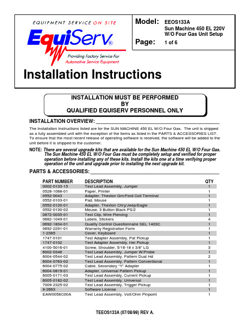
INSTALLATION OVERVIEW:_____________________________________________The Installation Instructions listed are for the SUN MACHINE 450 EL W/O Four Gas. The unit is shipped as a fully assembled unit with the exception of the items as listed in the PARTS & ACCESSORIES LIST.To ensure that the most recent release of operating software is received, the software will be added to the unit before it is shipped to the customer.NOTE: There are several upgrade kits that are available for the Sun Machine 450 EL W/O Four Gas.The Sun Machine 450 EL W/O Four Gas must be completely setup and verified for proper operation before installing any of these kits. Install the kits one at a time verifying proper operation of the unit and upgrade prior to installing the next upgrade kit.PARTS & ACCESSORIES:_______________________________________________PART NUMBERDESCRIPTION QTY 0002-0133-15Test Lead Assembly, Jumper 10528-1088-01Paper, Printer 10552-0043Adapter, Thexton Gm/Ford Coil Terminal 10552-0103-01Pad, Mouse 10552-0120-01Adapter, Thexton Chry/Jeep/Eagle 10552-0130-02Mouse, 3 Button Black PS/210672-0035-01Test Clip, Wire Piercing 10682-1049-01Labels, Stickers 40692-1834-01Quality Control Questionnaire SEL 1403C 10692-2291-01Warranty Registration Form 11-2385Cover, Keyboard 11747-0101Test Adapter Assembly, Pat Pickup 11747-0102Test Adapter Assembly, Hei Pickup 14100-5016-01Screw, Shoulder, 5/16-18 x 3/8” LG 36002-0346Test Lead Assembly, Jumper W/Probe 16004-0544-02Test Lead Assembly, Pattern Dual Hd 26004-0763-02Test Lead Assembly, Pattern Conventional 16004-0775-02Cable, Secondary “Y” Adapter 16004-0819-01Adapter, Universal Pattern Pickup 16005-0171-03Test Lead Assembly, Current Pickup 16005-0182-02Test Lead Assembly, Universal 17009-2325-02Test Lead Assembly, Trigger Pickup 18-2663Software License1EAW0058C00A Test Lead Assembly, Volt/Ohm Pinpoint 1Model:EEOS133A Sun Machine 450 EL 220VW/O Four Gas Unit SetupPage: 1 of 6Installation InstructionsPART NUMBER DESCRIPTION QTYEAW0060C00A Cable, Adapto1SS1495POP (Point Of Purchase) Kit1TEEOS133A Installation Instructions1ZEE0S140A Operators Manual1 REQUIRED TOOLS:____________________________________________________•Complete Tool KitINSTALLATION INSTRUCTIONS:_________________________________________ NOTE:Steps 1 through 5 will require two or more people.1. Cut and remove the straps. Carefully slide the unit carton off the shipping pallet. Remove the topof the shipping carton.2. Remove the carton by sliding the carton over top of the unit.3. Remove foam packing from around the sides of the unit.4. Lean the Sun Machine 450 EL so that half of the foam base can be removed.5. Lean the Sun Machine 450 EL so that other half of the foam base can be removed.6. Remove tape from ALL drawers and covers.7. Remove bubble wrap from Keyboard, located in the keyboard drawer.8. Inventory all items using the Parts & Accessories List and inspect for damage. The UnitAccessories are located in the bottom drawer of the unit. The Literature Kit is also located in the bottom drawer of the unit.NOTE:Any software or hardware owners’ manuals and pre-loaded software that come with the computer, such as Microsoft® Windows® 98 and the Sun Machine 450 ELoperating Software Package, are located in the bottom drawer of the unit.NOTE:Any REGISTRATION CARDS for the installed software such as Microsoft® Windows®98 must be filled out and sent in by the customer to ensure compliance with anysoftware licensing agreements.9. The boom is shipped in the lower position and will need to be raised to proper height.10. Open the back cover of the unit, locate the boom journal and remove the stop bolt on the boom.Raise the boom approximately 7 inches to expose new stop bolt hole; place the stop bolt into the new hole.11. Locate the shoulder screws (4100-5016-01), install the shoulder screws in the three holes at thebottom of the boom journal. The shoulder screw heads must be on the inside of the journal.12. The monitor is shipped separately from the unit. Remove the monitor from the box and inspectthe monitor for damage.13. Remove the swivel base of the monitor if attached.NOTE: If you are MOUNTING a 15” Sampo monitor, the Back Mounting bracket must be turned around as shown in Figure 1.BACKFigure 1, Monitor Base Plate for 15” Sampo Monitor.14. Place the monitor into the monitor base plate with the back of the monitor pushed snug againstthe back bracket. Slide the front bracket snug up to the front of the monitor and tighten the nuts of the brackets.15. Fasten the Velcro straps over the top of the monitor and snug down.16. Discard the A.C. Cable supplied with the monitor. Use the A.C. Cable found attached to the topof the unit.17. Connect monitor power, data, mic and audio cables to the unit.18. Locate the Mouse (0552-0130-02) and install the Mouse cable to the mouse connector of theconnector plate on the left side of the unit.19. Locate the printer paper (0528-1088-01) in the bottom storage drawer. Load printer paper intopaper cassette of the Printer (100 Sheets maximum). A portion of the remaining paper can be placed under the Printer.20. Connect all Test Leads to the respective connectors located on the boom of the Sun Machine 450EL. Store any unused leads and accessories in the lower storage drawer.Starting Windows 98 for the first time21. Turn on the analyzer. Windows will boot.22. When prompted: Enter the shop owner’s name in the Name: field, and the shop name in theCompany: field, then select Next >.23. The end-user (customer) must select I accept the agreement to accept the LicenseAgreement, then select Next >.24. Enter the Product Key number from the Certificate of Authenticity found on the GettingStarted Microsoft Windows 98 book that came with the analyzer, then select Next >.25. Select Finish.26. Enter the shop owner’s name in the User Name: field, then select OK. Do Not Enter APassword.27. Date/Time Properties: Select your time zone, set the date and time, select Apply, then selectOK.28. Enter the validation code and select OK.29. You will be prompted to insert the Initial Install Floppy disk into the unit. Place the Sun MachineInitial Installation disk in the floppy drive then select OK.30. You will be prompted to insert the Software Installation Floppy disk into the unit. Place the SunMachine Software Installation disk in the floppy drive then select OK.31. Deselect the Show this screen each time Windows starts box on the Welcome window.32. Close the Welcome window by pressing the X in the upper right corner of the Welcome window. Configure the Modem33. Double-click the RapidComm Voice desktop icon.34. Select Next > on the RapidComm Voice Setup Wizard window.35. Select I Agree on the RapidComm Voice Setup Wizard window.36. Complete the requested information and select Next > on the next two RapidComm VoiceSetup Wizard windows.37. Complete the requested information and select Close on the Location Information window.38. Select Next > on the RapidComm Voice Setup Wizard window.39. Select Finish on the RapidComm Voice Setup Wizard window.40. Select View on the RapidComm Voice window.41. Select Speakerphone on the drop-down menu.42. Select View on the RapidComm Voice window.43. Select Speed Dial on the drop-down menu.44. Set the Speaker Volume to maximum using the slide bar.45. Set the Microphone Volume to about one third maximum using the slide bar.46. Close the RapidComm Voice window by pressing the X in the upper right corner of the window.Monitor Display Position Adjustment (DOS Mode)When entering or leaving the Sun Machine program, if the monitor screen jumps to the right or left,perform steps 48 through 56 to correct.47. Perform the following steps only while in the Sun Machine program.48. Using the front buttons on the monitor, select the OSD button. This will bring up a monitoradjustment window.49. Using the Select "+" or "–" buttons on the front of the monitor, highlight Horizontal Positionsymbol, as shown in figure 2 below.50. Using the Adjust "+" or "–" buttons on the front of the monitor, adjust the horizontal position tothe center of the monitor screen.51. Using the Select "+" or "–" buttons on the front of the monitor, highlight Horizontal Sizingsymbol, as shown in figure 1 below.52. Using the Adjust "+" or "–" buttons on the front of the monitor, adjust the horizontal size to thedesired size on the monitor screen.53. Using the Select "+" or "–" buttons on the front of the monitor, highlight Vertical Positionsymbol, as shown in figure 1 below.54. Using the Adjust "+" or "–" buttons on the front of the monitor, adjust the vertical position to thecenter of the monitor screen.55. Using the Select "+" or "–" buttons on the front of the monitor, highlight Vertical Sizing symbol,as shown in figure 1 below.56. Using the Adjust "+" or "–" buttons on the front of the monitor, adjust the vertical to the desiredsize on the monitor screen.Figure 2, Monitor Adjustment SymbolsCheck Printer Selection57. Select Start ⇒ Settings ⇒ Printers . Using Table 1. Printer Setup, is the correct printer selectedfor the installed printer? If printer is correct go to step 65.58. Select the Add Printer Wizard , select Next >.59. Select the printer Manufacturer and Printer from the following list then select Next >.M odel of Installed Printer S elect Manufacturer from list S elect Printer from listO kidata OL600E H P L aserJet II PO kiPage 6E H PL aserJet 4 PT able 1, Printer Setup 60. Select LPT1: Printer Port , from the Available Ports window then select Next >.61. Do not change the “Printer Name” that is currently listed, select Yes for “Make this printer yourdefault printer” then select Next >.62. Select “Yes” for print test page, select Finish .63. Wait for printer to print page. If the printer printed the page, select “Yes”. If the page did notprint select “No” and troubleshoot accordingly.HorizontalPosition Vertical Position Horizontal Sizing Vertical SizingSetting Printer Properties64. Select the Start ⇒ Settings ⇒ Printers.65. Press the right mouse button over the printer icon for the installed printer on the Printers page.66. Select Properties on the dialog.67. Select the Details tab.68. Select the Port Settings… button.69. Verify that there is no check mark on Spool MS-DOS print jobs, then select OK.70. Select the OK button on the printer properties dialog.71. Close the Printers window by pressing the X in the upper right corner of the window.Setting Network Adapter PropertiesNOTE: Perform this procedure only if this unit is not being attached to a network.72. Select the Start ⇒ Settings ⇒ Control Panel ⇒System.73. Select the Device Manager Tab from the System Properties Window.74. Select the plus sign (+) to the left of Network Adapters to expand the list.75. Highlight Intel 82558-Based… adapter then select Properties in the Device Manager Tab.76. Under the General tab in the Intel 82558-Based… dialog box place a check mark in the box nextto Disable in this hardware profile. Select OK ⇒ OK.77. Select Start ⇒ Shut Down ⇒ Restart ⇒ OK, this will restart the computer so the changes willtake effect.Check CD-ROM Properties78. Select the Start ⇒ Settings ⇒ Control Panel ⇒System.79. Select the Device Manager Tab from the System Properties Window.80. Select the plus sign (+) to the left of CD-ROM to expand the list.81. Select a CD-ROM drive.82. Select Properties on the Device Manager tab.83. Select Settings on the CD-ROM Properties dialog.84. Verify that there is no check mark on Auto insert notification on the Settings tab.85. Select the OK button on the CD-ROM Properties dialog.86. Repeat steps 61 through 65 for each CD-ROM installed.87. Select the OK button on the System Properties dialog.Check Power Properties88. Select Start ⇒ Settings ⇒ Control Panel.89. Double-click the Power Management icon.90. Set Turn off monitor and Turn off hard disks to Never.91. Select the OK button on the Power Management Properties dialog.92. Close the Control Panel window by pressing the X in the upper right corner of the window.INSTALLATION COMPLETE。
Lorex L15LD400系列快速安装指南说明书

W W W.L O R E X C C T V.C O M information in tHis document is suBject to cHange witHout notice. as our products are suBject to continuous improvement, Lorex tecHnoLogy and our suBsidiaries reserve tHe rigHt to modify product design, specificationsand prices, witHout notice and witHout incurring any oBLigation. e&oe © 2007 Lorex. aLL rigHts reserved.L15LD400 SeriesQuick start guidePACKAGE CONTENTS AND INSTALLATION GUIDE:System Contents:1 - 15” 4 Channel LCD Monitor with 160GB HDD 1 - 10 ft Ethernet Cable 1 - Remote Control Skills - IntermediateSkills - AdvancedSTEP 1 - SET UP YOUR MONITOR FIRSTCongratulations! You have completed Step 1 successfully. You can now view, recordand playback images on your monitor.connect the first camera to the cH1 input. follow the same steps to connect theadditional cameras.CONNECT CAMERAS TO THE MONITOR:connect one end of the ethernet cable to one of the router’s (not included) Lanports and the other end to monitor’s network port located at the bottom of themonitor. see picture below showing a generic Lan/wan connection.CONNECT ETHERNET CABLE:connect the 6 pin end of the mouse included with your system to the ps2 port ofthe monitor.CONNECT THE MOUSE:WAN (WIDEAREA NETWORK)LAN (LOCAL AREA NETWORK)TO YOUR COMPUTERTO YOUR MONITORBACK OF THE ROUTER SHOWNMOUSE CONTROLAVAILABLE1. Connect the Female BNC end of the supplied 60’ extension cable to the camera.Connect the male Power end of the extension cable to the camera.2. Connect the Female end of the supplied 60’ extension cable to an open BNCcamera input on the back of the System. Connect the female Power end of theextension cable to one of end of the 4 in one power adaptor.123connect one end of the power adaptor to the monitor, the other end to an electricaloutlet. this unit powers on once it is plugged in to the power outlet.** after you see all four (4) camera images on your monitor screen, remove theprotective film from camera(s) and monitor screen.CONNECT POWER CABLE:41. press the menu button from the front panel of the monitor (or remote control), or use themouse and click the menu icon located at the bottom of the monitor screen (show andhide screen becomes available when the mouse pointer is placed at the bottom of the monitor).2. dvr Log in screen appears soon after the menu button is pressed asking for a password.note: user id By defauLt is admin. password is numeric and not necessarily needed forinitial menu setup. press enter to enter the main menu.3. on the menu screen select configuration and click enter.4. select time and date setup to change or alter the factory default settings and press esc toexit this menu.SET THE TIME AND DATE:5Make sure thatthe Date and Timeare set prior torecording.IMPORTANT NOTE: The ends of the extension cable are NOTthe same - one end has a Male power port, and the other hasa Female power port. Before permanently running the CameraExtension Cable, make sure that the cable has been orientedbetween the Camera and the unit correctly1. access the main menu setup screens, and navigate to the systemmenu - externaL device - tcp/ip setup - ip setup option.2. record the mac address of your system. this information is necessaryfor the ddns setup process.3. confirm that the dHcp mode is set to automatic. this will allow yoursystem to lease an ip address from your router. if the system not set toautomatic, change the setting and click ip detect - the system willobtain an ip address.4. the ip port is 50000 by default. the ip address, gateway and subnet areassigned to your system by your router. if the settings are not displayed,and the unit is set to dHcp mode: automatic, you may need to click ipdetect - the system will obtain an ip address.STEP 2 - SET UP LOCAL VIEWING ON YOUR PCRETRIEVE SYSTEM INFORMATION:RECORD THE IP AND MAC ADDRESSES IN THE SECTION BELOW:insert the Lorex client 2.0 software cd into your local computer’scd rom drive and proceed with the installation.INSTALL SOFTWARE:(on your local computer)12software installation.3close the cd menu screen. a Lorex client icon will appear on yourdesktop.LOREX CLIENT 2.0 SOFTWARE:(on your local computer)4*your oBservation system mustBe connected to a router prior topowering it on.for Lorex client softwarerequirements, please refer topage 9 of this guide.12345double-click the Lorex client 2.0 software icon on your desktop to run theprogram.RUN THE LOREX CLIENT 2.0 SOFTWARE:(on your local computer)note: the system will lease networkinginformation from your router. if you wishto set your information manually, thenset the dHcp mode to manuaL. pleaseconsult your Hardware manual for furthermenu options.STEP 2 - SET UP LOCAL VIEWING ON YOUR PCCONTINUEDbutton from the Lorex client 2.0 software screen.1. select the ip/port tab.2. click manuaL (for local viewing).3. name: enter a name for the system. e.g. office4. address: add the ip address recorded earlier at step 2 - 15. port: By default is set to 500006. user id : By default is admin7. password : Leave it blank8. press save to add the system name you have created.LOREX CLIENT 2.0 REMOTE ACCESS SETUP(on your local computer for local viewing):567Congratulations! You have completed Step successfully. You can now view and playback images on your local computer over the Local Area Network (LAN).STEP 3 - SET UP INTERNET REMOTE SECURITY MONITORINGPORT FORWARD YOUR ROUTER:open your web browser (internet explorer by default) and enter in the address bar.DDNS SET-UP:12port forward your router first before proceeding with the set-up (port 50000).all routers are different. to port forward your router, please refer to your router’s user manual.a router configuration guide is available on your Lorex client software cd and also on /support in the consumer’s guide section.3complete the new user fields with your personal information:• user name - enter the desired user name for connection.• user password / confirm password - enter and confirm a password for the connection.note: the username and password provided are not the same as the admin/password on the observation system. these credentials are used for your specific connection to your unit.• emaiL - enter your email address.press the oK button to save the settings.a successful registration window will appear.CREATE NEW USER INFORMATION:4STEP 3 - SET UP INTERNET REMOTE SECURITY MONITORINGonce the account has been created, you will need to login using your credentials (as set in step 4).once the username and password have been entered, press the Log in button to access the configuration menu.LOGIN:5select the add dvr link from the top of the page.ADD DVR:67STEP 3 - SET UP INTERNET REMOTE SECURITYMONITORING • set the ddns enaBLe to on • click on registerthe following will automatically complete after clicking the register option:• dns server - confirm that the ip address is set to 202.133.244.128• intervaL - set an interval for the dvr to auto-update its ip address to ddns server (d- days / H- hours / m- minutes).• register - connect to the ddns server and register the dvr information to ddns database • dns status - indicates the current status of ddns connection.• ip address - indicates the local ip address assigned by the router (the internal ip address of your system).• ip port - indicates the current port number in the system (50000 by default).• remain time - indicate the remaining time until the system next updates the ip address with the ddns service.• Last registration date - indicates the last successful date and time that an update occurred. save the changes, and exit from the menu.ENABLE DDNS SETTINGS:8CONTINUEDthe remote connection information needs to be added to the Lorex client software to allow for a remote connection (using ddns).LOREX CLIENT 2.0 REMOTE ACCESS SETUP:91. Load the Lorex client2.0 software . click on setup to add the configuration.2. the remote viewer setup window will load to the ip/port tab. click on the ddns option (all settings will be greyed out).3. enter your ddns information as follows:• user name - enter the user name you configured on the ddns website (default is set to group as an example, and can be deleted).• dvr name - enter the dvr name you configured on the ddns website.4. click the save Button to accept the settings.5. click on the get ip button to retrieve the ip address and port number from the ddns server.6. enter the user id and password for the observation system:• user id - admin (default)• password - leave blank (default)note: it is highly recommended that you change the system password. please refer to your Hardware manual for menu settings.7. press oK to save the settings, and close the configuration window.video from the observation system can be viewed using theCongratulations! You have completed Step successfully. You can now view and playback images on your remote computer over the Internet.10MyBusinessRECOMMENDED TIPSptZ1234fuLL screen cH 1 ~4Quad modemenuto pan/tiLt/Zoomcamerato view image in picturein picture modeZoompLay in seQuenceopens searcH win-dowQuicK pLayBacKtilt the monitor up to loacte yourmonitor’s connections.LOCATE MONITOR CONNECTIONS:FUNCTION ICONS - AVAILABE FOR USEONLY THROUGH A MOUSELOREX CLIENT 2.0 SOFTWARE REQUIREMENTS:the Lorex client 2.0 software (included with theobservation system) has the following installationrequirements:MiniMuM SySteM RequiReMentS:operating system: windows 2000, windows xpHome edition, windows xp professionalprocessor: pentium 4 - 1.5 gHz processor (orequivalent)memory: 256 mB ramHard drive: 50 mB - installation space required.* additional Hard drive space required for recording.recorded file size will vary depending on recordingquality settingsRecoMMended SySteM RequiReMentS:operating system: windows xp Home edition,windows xp professionalprocessor: pentium 4 / 3 gHz processor (orequivalent)memory: 1024 mB ramHard drive: 50 mB - installation space required* additional Hard drive space required for recording.recorded file size will vary depending on recordingquality settings** requires a high speed internet connection(minimum upload speed: 256Kb/s, download speed512Kb/s) and a broadband router – not included.typical network remote viewing at 1-2 fps.please refer to the Lorex client v2 softwareuser guide included with your observationsystem for further details.visit the Lorex support website at http://www. for information on windowsvista compatibility.function icons can be located at thebottom of the monitor screen (asshown above). a show and Hidescreen readily becomes availablewhen the mouse pointer is pointed tothe bottom of the monitor.formatting tHe new Hard drive:the new Hard drive must be formatted. if a new Hard drive is detected, the system will prompt you to format the drive. please refer to the system’s user manual for Hdd installation.HDD INSTALLATION:the system comes with a pre-installed Hard drive, however the unit will work with a replacement single Hard drive (up to 400gB).note: make sure that the system is off and the power cable has been disconnected before changing the Hard drive. for detailed instructions, check your user’s manual included with the system.TIP ON CAMERA MOUNTING:note: test the cameras prior to selecting a permanent mounting location by temporarily connecting the cameras and cables toyour L15Ld400 dvr combo system.setting tHe new drive to master:• refer to the general jumper pin setting on Hdd surface (generally located on a sticker on the top of the drive).• set the jumper pin set to master (1 drive). note: use a Hard drive model with a power supply rated udma66 or higher.connecting tHe ide caBLe:• confirm the ide cable is securely connected within the system.RECOMMENDED TIPS CONTINUEDnote: you must have an active internet connection to the observation system to be able to perform remote viewing or playback. remote access is dependant on your connection speed, internet traffic and other network factors - the speed is normally 1~2 fps (frames per second).for faster playback, it is recommended to download previously recorded video using the backup function and play it back using Backup player 2.0 software - refer to the user manual for details. regardless of the network playback speed, video is being recorded on your system in real time, and can be viewed when you are at the system or through the backup player.TIP ON REMOTE VIEWING AND PLAYBACK:page intentionally left blankL15LD400 Series Quick Set-Up Guide R21 It’s all on the Web for detailed setup information, please refer to your user’s manual. for additional information about determining your ip address, configuring your router, and port forwarding, please visit our website /support and click consumer guides section or view guides from the Lorex client 2.0 software cd included with your system.emailsupport:*********************toll free technical support - north america: 1-888-42 Lorex (1-888-425-6739)toll free technical support - international (outside of north america): 00-800-425-6739-0Lorex international website - PRODUCT SUPPORT QUICK SET-UP GUIDE USER’S MANUALFAQ Specification Sheet User’s Manual Lorex Client Software Manual Quick Start Guide Port forwarding GuideBasics of Remote VideoAccess GuidePRODUCT SUPPORT。
亚拓安装调试图解

亚拓450从零安装调试详细讲解T-REX 450 SE-组装方式/调整/设定参考第1步:首先将机身固定柱和主轴固定座及电池固定座左侧两颗螺丝拆下,方便服务器安装第2步:将第一颗服务器由内往外安装第3步:同样的由内往外安装第二颗服务器,并将讯号线排列整齐用速线带固定,切记(1.速线带头在机身内侧2.在固定于册版的地方用透明胶带包覆两圈,防止组装时讯号线破损)第4步:将伺服机讯号线由内侧版经沟槽穿往机身外侧第5步,将服务器的讯号线整理后,再用蛇管包覆第6步:将机身固定柱和主轴固定座及电池固定座左侧两颗螺丝装回原来位置记得要上螺丝胶喔第7步:将中间的侧版固定柱套入,并对准螺丝孔.将马达固定座装上下侧版第8步:1.利用马达固定座将上.下侧版组合2.将中侧版固定柱锁上螺丝第9步:将服务器讯号线穿过上.下侧版并将左侧三颗螺丝锁上第10步:右侧版先锁上1的螺丝,其它两颗先不锁第11步:将所需的马达同齿固定后,在将马达固定在马达坐上第12步:将马达线穿过机身底板和组装好的脚架,并将脚架固定第13步:将皮带穿过尾管(注意皮带的方向性)并将尾服务器座套入尾管,然后跟机身组合,并将垂直/水平/支撑架装上,调整皮带的松紧度后上紧尾管固定座的螺丝第14步:金属尾传动轮座组固定前,需确认与尾管固定座呈平行状态第15步:陀螺仪的整线后用蛇管包覆第16步:将陀螺仪用双面胶固定在尾管固定座上后,将包覆好的讯号线穿过上.下侧版后再将右侧版的两颗螺丝上紧(陀螺仪安装在尾固定座的下方,以防炸机时被副翼打到)第17步:先抓出尾服务器的中点,并将球头固定在服务器的摆臂上(上下两个圈是行程终点),并将服务器固定在尾伺服座上第18步:装好尾服务器时,套上连杆后,注意,这是重点1,尾舵控制组需在尾主轴中央2.调整尾服务器座让连杆跟尾管平行3.尾服务器摆臂球头需在中点4. 尾连杆和尾管尽量跟尾管呈平行以上确定后在固定尾伺服座螺丝第19步:1.将主轴上的连杆按说明书上的长度组装,并套上摆臂平衡杆先量好两边相等长度后套入平衡杆重垂在装上平衡翼2.将主轴和机身组合第20步:组合好后请注意大齿盘于机身的间隙,不能摩擦到机身或尾传动轮第21步:调整马达铜齿的高度并将铜齿固定螺丝上紧,调整马达与大齿盘的间隙后再将马达固定螺丝上紧第22步:1.用2mm钻尾将欲锁球头的摆臂扩孔2.将球头利用螺母固定在摆臂上3.将多余的摆臂去掉.以免摆动时干涉4.将服务器连杆依说明书长度组装好第23步:将组装好的摆臂套上服务器,先不上服务器螺丝,以便调整时需拆下,此时连杆都是呈垂直状态第24步:接收的整理1.用热缩套管或由机的油管将接收线的前端包覆,以防接收线和侧版接触而出现干扰现象,相信很多人有这个经验2.用1mm的泡棉将接受包覆并用透明胶带在包覆,以防日久泡棉脱落,这可以防止摔机后的碰撞以以多一层的防干扰的作用第25步:1.用双面胶将接收固定在底板2.将讯号线接上接收第26步:1.用打火机熏烤将热缩套管定型你要的角度2.在用热缩套管将整理的接收线固定在线管上第27步:将电子变速器的讯号线穿过脚架和底板之间并接上接收(马达线先不要接,以便遥控器设定和调机)------------------以上是机械及电子部件的安装---------------第28步:控的设置,打开遥控器进入SW ASH TYP,打开选项选择120度第29步:接上电池,将摆臂尽量以90度脚平行装上,并推油门游戏杆以确认伺服机的方向正确,如有反向,可进入REV.SW个别调整正确方向第30步:如摆臂有微些差距,可进入sub trim个别微调至所有摆臂至平行,调整好后记得看看十字盘是否平行,如没平行,调整十字盘连杆使起平行既可第31步:接下来先将主旋翼做好静态平衡后,装上直升机,并将服务器螺丝锁上第32步:进入遥控器选项里的PIT.CURV.1.并将油门游戏杆推至中点2.在NORM设定页面3.将EXP显至ON的位置,这可以自行调整曲线较为顺畅第33步:已有贴配重贴纸的桨为主1.将螺距规套上,并以螺距规的上沿跟平衡杆呈平行2.此时应为0度,如没0度,可依差距大小调整连杆使其成为0度第34步:将油门游戏杆推至最高并记下为+11度第35步:将油门推至最低,并记下为-11度,对高手来说,这个螺距应该是可以的第36步:如想减少螺距行程,可进入swash mix的PIT降低%数(5%为一度左右),所以我降了10%,此时螺距为(-9 0 +9)这应该适合一般飞友第37步:接下来是在进入PIT. CURV设定NORM的螺距,第一点位置设定为-2度,此时数据为38%第38步:接着将油门游戏杆推至中点3的位置(约是停悬点),为+5度,此时该点数据为75%第39步:在来是将刚刚设定的38%和75%以及最高的100%三点中的曲线,设定调整一条顺畅的拋物线,这样一来,在操控的过程会顺畅许多,不会又高高低低的情况发生第40步:接下来进入THRO CHRV的NORM页面设定油门曲线,首先在第3点(中点)位置将数据设定为68%第41步:接下来是一般人常遇到也是最让你头痛的尾巴设定,如果你刚刚再组装的时候有按照图示安装,基本上尾服务器的中立点已经抓好了,所以不会有偏的问题发生,只要了解陀螺一的功能和调整就可以了,A.接上电源如果灯恒亮,就表示锁头模式,1数字/模拟的切换开关,如果你用的尾舵机不是数码的,必须将开关切至OFF的位置,如果是数码舵机择切换至ON的位置2.陀螺仪反向开关3.延迟开关,如果是数字服务器这个开关可以不用管他,在O的位置.如是用模拟服务器,感度以将很低仍有追踪现象,可调整此开关改善4.陀螺仪行程开关,如行程太大会产生操控尾舵时,定点会有抖几下的情况,可降低此行程来改善第42步:确认方向舵方向,通常尾舵控制组跟方向游戏杆是反方向移动,这才是正确的第43步:确认好后接下来进入遥控器GYRO SENS AUTO页面设定陀螺仪感度POS.0为一般飞行感度设定POS.1为3D飞行感度设定设定好感度后不要忘了也要进入由上角将POS.0和POS.1个别设定好,如此一来,感度才会跟着你切换的飞行模式而改变资料来源:亚拓台湾官网论坛第44步:设定好后,将电子变速器和马达的线依颜色接上,并将固定第45步:设定的过程中,有些飞友会利用这个页面调整服务器的行程,来达到所需的螺距,这是错误的,就算调整好了,+-数据不相等,这会产生打动作时,左右的速度不均现象第46步:还有一种错误的调整螺距的方式,如图示,降低/提高螺距曲线的%数来迎合所需的螺距,这也会让你在操控时,游戏杆上下不均匀,也缩短了螺距变化的空间,所谓一步错步步错!第47步:接下来是调整双桨,以量螺距的桨为机准桨(贴配重贴纸的桨),此桨不动视另一只桨高低作调整就可以了,完工!。
莫勒控制器系统安装手册说明书
1PageProgrammable logic controllersPLCs 1-2xSystem 1-4Modular I/O system XI/ON1-6Networkable motor starters xStart-XS1 1-8Networking PS40 series 1-10Networking xSystem1-11Networking display and operating devices 1-12Networking embedded HMI-PLCs 1-13Engineering XC100/XC200 1-14Engineering PS4 1-16Engineering EM4 and LE41-191Programmable logic controllersThe programmable (logic) controller (PLC) is anelectronic device for machine or process control.The PLC receives signals via inputs, processesthem according to the instructions of a program,and transfers signals to the outputs.The program is created using programmingsoftware which is able to link inputs and outputsin any required sequence, to measure time, oreven carry out arithmetic operations.The most important specifications of a PLC are itsmaximum number of inputs/outputs, its memorysize and its processing speed.The PS40 Series and the new xSystem are the twoautomation systems offered by Moeller. These aredescribed below.PS40 SeriesCompact PLCsThe PS4 compact PLCs have the following systemcharacteristics:•Standard programming•Remote and local expansion options•Integrated fieldbus interface (Suconet)•Plug-in screw terminals•Small, compact in sizeThe controllers in this range are very versatile witha wide range of features, such as integratedsetpoint potentiometers, analog inputs/outputs ormemory expansion modules (from PS4-150).Moellers' entire PLC range is described in the MainCatalogue for Automation Systems and Drives, aswell as in the Product overview for automation.Modular PLCsThe PS416 modular PLC has the following keyfeatures:•High processing speed•Compact size•Wide range of networking options•Extensive memorySucosoft programming softwareSucosoft is the name of the software forprogramming the PS40 PLCs.Program examples are provided in the PLCBeginners' Guide “Automation withProgrammable Logic Controllers” (FB2700-017).1PS4/EM4:Compact PLC or expansion module LE4:Local expansionPS416: Modular PLC1xSystemxSystem is Moeller's latest modular automationsystem. It can be configured for the individualrequirements of small or large applications.xSystem reduces the hardware and softwareinterfaces required. The system features ITfunctions that are already integrated.The XSoft software combines programming,configuring, testing, commissioning andvisualization functions in a single tool designed forthe entire xSystem product range.1System components •Modular PLCs –XC100 h8 DI, 6 DO, CANopen, RS 232, 4interrupt inputsSlot for multimedia memory card,64–256KByte program/data memory, 4/8KByte for retentive data, 0.5ms/1000instructions –XC200 g8DI,6DO, CANopen, RS 232, Ethernet, 2counters, 2 interrupt inputs, WEB/OPC server, USB, locally expandable with XI/OC I/O modules, 256–512 KByte program/data memory, 0.05 ms/1000 instructions •Text display PLCs–Modular text display PLCs aConsisting of XC100, up to 3XI/OC modules and LCD text display with 4 x 20 or 8x 40lines/characters–Compact text display PLC bMinimum mounting dimensions and high interface integration density (10DI, 8DO, 8DIO, 2AI, 2AO, 2 counter inputs, 2interrupt inputs, 1 encoder input)•XI/OC input/output modules c –Can be fitted to the XC100/200 (max.15modules)–Plug-in terminals with screw or springloaded terminal •XSoft–Programming, configuring,testing/commissioning in a single toolRefer to the following product overview and manuals for further information:–Automation product overview (AWB2700-7546)–XC100 hardware and engineering (AWB2724-1453)–XC200 hardware and engineering (AWB2724-1491)–XI/OC hardware and engineering (AWB2725-1452)–XV100 hardware and engineering (AWB2726-1461)–xStart-XS1 hardware and engineering (AWB2700-1426)–XSoft PLC programming (AWB2700-1437)–Function blocks for XSoft (AWB2786-1456); including data handling function blocks for text display PLCs The latest edition is available from/support : Enter the numbers shown in brackets, e.g.“AWB2725-1452G”, as a search term.1XI/ON – the conceptXI/ON is a modular I/O system for use in industrialautomation applications. It links sensors andactuators on the field level with the higher-levelcontroller. Fieldbus protocols PROFIBUS-DP,CANopen and DeviceNet are supported.XI/ON offers modules for virtually everyapplication:•Digital input and output modules•Analog input and output modules•Technology modulesA XI/ON station consists of a gateway, powersupply modules and I/O modules.A complete XI/ON structure counts as a single busstation in any fieldbus structure and therefore onlyrequires one bus address. The individual XI/ONperipheral modules are therefore independent ofthe higher-level fieldbus.The I/O modules consist of a combination of abase module designed as a terminal block, and aplug-in electronics module.The XI/ON peripheral modules are linked to thefieldbus via the XI/ON gateway. This is used forthe communication between the XI/ON stationand the other fieldbus stations.a Gatewayb Power supply modulec Electronics module in block designd Electronics module in slice designe End platef Base module in slice designg Base module in block designbadefcg1FlexibilityEach XI/ON station can be adapted exactly for the required number of channels since the modules are available in different levels of granularity.For example, digital input modules with 2, 4, 16 or 32 channels are available in slice or block design.A XI/ON station can contain modules in any combination. This enables the system to be adapted to virtually any application in industrial automation.Compact designThe narrow mounting width of the XI/ON modules (gateway 50.4 mm; slice 12.6 mm, block100.8mm) and the low mounting height make the system ideal for use in applications where space is at a premium.Simple handlingApart from the gateway, all XI/ON modules consist of a base module and an electronics module.The gateway and the base modules can be snap-fitted on mounting rails. The electronicsmodules can then be plugged simply onto the assigned base module.The base modules are available as terminal blocks. They are wired either with spring-loaded or screw terminals. The electronic modules can be fitted or removed during commissioning or for maintenance without disturbing the wiring.A design coding feature ensures that theelectronic modules can only be fitted at the correct locations provided.I/Oassistant diagnostics and engineering softwareThe I/Oassistant provides support during the entire planning and implementation phase of an I/O system. It provides help for engineering the stations, the configuration and for setting the parameters. The software is used forcommissioning systems and carrying out tests and diagnostics on the stations.The entire documentation for the station, including a parts list for ordering, can begenerated after the engineering phase.1xStart-XS1xStart-XS1 is the modular, networkable version ofthe tried and tested motor starter from Moeller. Itconnects the motors with the XI/ON system andthus ensures flexible availability between systems,irrespective of the fieldbus in use.xStart-XS1 offers DOL and reversing starters indifferent ratings and available with or without atrip-indicating auxiliary contact (AGM).The xStart-XS1 modules consist of a base moduleand a power module that contains the tried andtested PKZM0 motor-protective circuit-breakerand one or two DILEM contactors. They enable theconnection of assigned motor ratings up to 4.0 kWat a rated operational voltage U e of 400V AC.FlexibilityYou can adapt xStart-XS1 exactly to therequirements of the system used.xStart-XS1 can be used at any position on a XI/ONstation so that you can organise your stationconveniently into system areas.The motor can be disconnected at the machine byusing the rotary handle.MountingThe complete module is mounted by simplysnap-fitting it onto two top-hat rails. You can alsosimply mount the base module and add the powersection at a later time. Mounting and removal arecarried out without any tools.a XI/ON gatewayb Supply modulec XI/ON I/O modulesd xStart-XS1 DOLstarter modulee xStart-XS1 reversingstarter moduleab c cbd e d1Power supply accessories are available for reducing wiring costs. If several xStart-XS1 modules are mounted next to each other, the power can be fed via a distribution system. This power distribution is available for an operating current of up to 63 A.a Incoming terminal forthree-phase commoning linkb Three-phase commoning link forup to 4 DOL starters withouttrip-indicating auxiliary contactAGMc DOL starter without AGMtrip-indicating auxiliary contact c1Networking PS40 SeriesP R O F I B U S -F M SS u c o n e t P R O F I B U S -D P PS4-141-MM1PS4-151-MM1PS4-201-MM1PS4-271-MM1PS4-341-MM1PS416-BGT...PS416-CPU...PS416-POW...PS416-INP ...PS416-OUT...PS416-AIN...PS416-AIO...PS416-CNT-200PS416-TCS-200PS416-NET...PS416-COM-200PS416-MOD-200EM4-101-...EM4-111-...EM4-201-DX2LE4-104-XP1LE4-108-...LE4-116-...LE4-206-...LE4-308-...LE4-622-CX1LE4-501-BS1LE4-503-BS1CM4-504-GS1CM4-505-GS1ZB4-501-UM4S40Suconet K + RS 232Suconet K + RS 232Suconet K + RS 232Suconet K + RS 232Suconet K + RS 232Suconet K (M/S)Modbus(SI)Suconet K/K1Suconet K/K1Suconet K EM4-204-DX1PROFIBUS-DPSuconet KLE4-633-CX1PROFIBUS-FMS (Slave)Suconet K, PROFIBUS-DP GatewayM o d b u s 64 kByte 64 kByte64 kByte 64 kByte 512 kBytePart No.Interfaceserial interface interface converter Programming softwareMemory2 x3 counter3 x 3 path measurement1Networking xSystemXC200+ XIOCXC100+ XIOCXC100-XV + XV100A N o p e n x S y s t e mt h e r n e tR O F I B U S -D P u c o n e t K o d b u s XC6001Networking Display and Operator Devices120 X 321119C A N o p e n S u c o n e t E t h e r n e tP R O F I B U S -D P D e v i c e N e t 120 X 32120 X 64240 X 64240 X 64120 X 323527320 X 2405656 320 X 240640 X 480504646320 X 240––320 X 240640 X 480640 X 480320 X 240–––1024 X 768800 X 600––320 X 240–Part no DisplayResolution Code LCD monochrome LCD monochrome LCD monochrome LCD monochrome LCD monochrome LCD monochromeMonochrome STN colour TFTMonochrome STN colour TFT colour Monochrome TFT TFT TFThMonochrome H M I (D i s p l a y a n d o p e r a t i n g d e v i c e )1Networking Embedded HMI-PLCNote: The XVH- ... devices are also availablewith RS 232 or MPI interface.320 X 240C A N o p e n S u c o n e t E t h e r n e tP R O F I B U S -D P D e v i c e N e t 640 X 480320 X 240320 X 240320 X 240640 X 480640 X 480800 X 600800 X 6001024 X 7681024 X 768320 X 240Part no Infra-red DisplayResolution Touch Infra-redInfra-red Resistive Resistive Infra-red Resistive Infra-red Resistive Infra-red ResistiveInfra-red STN colour TFTSTN colour STN colourSTN colour TFT TFT TFT TFT TFT TFTSTN colour1Device arrangementInstall the rack and the PLC horizontally in thecontrol cabinet – as shown in the following figure.Terminal assignmentThe terminals for the power supply and the localI/O have the following assignment:Wiring example of power supply unitThe voltage terminal 0VQ/24VQ is only used forthe power supply of the local 8 inputs and 6outputs, and is potentially isolated from the bus.The outputs 0 to 3 can be loaded with 500mAand the outputs 4 and 5 with 1A, each with a100% duty factor (DF) and a simultaneity factorof 1.The wiring example shows the wiring with aseparate power supply for the PLC and the IOterminals. If only one power supply is used, thefollowing terminals must be connected:24 V to 24VQ and 0 V to 0VQ.a Clearance > 50 mmb Clearance > 75 mm fromactive elementsc Cable duct%IX 0.0%IX 0.1%IX 0.2%IX 0.3%IX 0.4%IX 0.5%IX 0.6%IX 0.7%QX 0.1%QX 0.3%QX 0.524 V Q0 V Q0 V24 V1RS 232 serial interfaceThis interface is used by the XC100 to communicate with the PC. The physicalconnection is implemented via an RJ 45 interface. The interface is not isolated. The connector has the following assignment:You can use the COM1 or COM2 interface on the PC.You use the XT-SUB-D/RJ45 programming cable for the physical connection.CANopen interfacewith the following properties:•Surge impedance 108 to 132 O•Capacitance per unit length < 50 pF/mPinDesignation Description4GND Ground 5TxD Transmit Data 7GND Ground 8RxDReceive DataH 0 V H Q H 0 V Q H87654321B a u d r a t e [K b i t /s ]L e n g t h [m ]C a b l e c r o s s s e c t i o n [m m 2]L o o p r e s i s t a n c e [O /k m ]2010000.75 – 0.8016 1255000.50 – 0.6040 2502500.50 – 0.6040 5001000.34 – 0.6060 1000400.25 – 0.3470CAN_H CAN_GNDCAN_L1PS4-151-MM1 compact PLC•Wiring for a 230 V AC supply circuit•Relay contacts with different potentials: 230 VAC and 24 V DC•24 V DC inputs from an external power supplyunit, earthed operation*Insulation monitoring must be providedwhere the control circuits are not earthed.(EN60204-1 and VDE0100-725)**IEC/EN 60204-1 specifies that a controltransformer is required.1PS4-201-MM1 compact PLC •Shared power supply for PLC and inputs/outputs •Non-earthed operation with insulation monitoring*For operation without insulation monitoring, 0 V must be linked with the PE potential in the control circuits.N1PS4-341-MM1 compact PLC•Shared power supply for PLC andinputs/outputs•Non-earthed operation with insulationmonitoring*For operation without insulationmonitoring, 0 V must be linked with the PEpotential in the control circuits.N1Engineering EM4 and LE4EM4-201-DX2 expansion module and LE4-116-XD1 local expansion •Inputs and outputs have a separate power supply•Earthed operation*Insulation monitoring must be provided where the control circuits are not earthed.Notes 1。
图解Intel电脑组装全过程

图解Intel电脑组装全过程图解Intel电脑组装全过程DIY攒机第一步:安装CPU处理器当前市场中,英特尔处理器主要有32位与64位的赛扬与奔腾两种(酷睿目前已经上市,酷睿处理器是英特尔采用0.65制作工艺的全新处理器,采用了最新的架构,同样采用LGA775接口,在今后一段时间内,英特尔将全面主推酷睿处理器。
由于同样采用LGA775接口,因此安装方法与英特尔64位奔腾赛扬完全相同)。
32位的处理器采用了478针脚结构,而64位的则全部统一到LGA775平台。
由于两者价格差距已不再明显,因此小编推荐新装机用户选择64位的LGA775平台,32位的478针脚已不再是主流,不值得购买。
上图中我们可以看到,LGA 775接口的英特尔处理器全部采用了触点式设计,与478针管式设计相比,最大的优势是不用再去担心针脚折断的问题,但对处理器的插座要求则更高。
这是主板上的LGA775处理器的插座,大家可以看到,与针管设计的插座区别相当的大。
在安装CPU之前,我们要先打开插座,方法是:用适当的力向下微压固定CPU 的压杆,同时用力往外推压杆,使其脱离固定卡扣。
压杆脱离卡扣后,我们便可以顺利的将压杆拉起。
接下来,我们将固定处理器的盖子与压杆反方向提起。
LGA 775插座展现在我们的眼前。
在安装处理器时,需要特别注意。
大家可以仔细观察,在CPU处理器的一角上有一个三角形的标识,另外仔细观察主板上的CPU插座,同样会发现一个三角形的标识。
在安装时,处理器上印有三角标识的那个角要与主板上印有三角标识的那个角对齐,然后慢慢的将处理器轻压到位。
这不仅适用于英特尔的处理器,而且适用于目前所有的处理器,特别是对于采用针脚设计的处理器而言,如果方向不对则无法将CPU安装到全部位,大家在安装时要特别的注意。
将CPU安放到位以后,盖好扣盖,并反方向微用力扣下处理器的压杆。
至此CPU便被稳稳的安装到主板上,安装过程结束。
DIY攒机第二步:安装散热器由于CPU发热量较大,选择一款散热性能出色的散热器特别关键,但如果散热器安装不当,对散热的效果也会大打折扣。
克罗韦尔 Armor Compact GuardLogix 控制器安装指南 说明书

安装指南Armor Compact GuardLogix 控制器产品目录号 1769-L33ERMOS、1769-L36ERMOS、1769-L37ERMOS 主题页码关于Armor Compact GuardLogix 控制器3部件列表4所需组件4安装控制器4控制器接地5进行电源连接5打开机壳检修门5取出和安装内存卡6连接 USB 端口7进行网络连接7设置网络 IP 地址8更新控制器10创建控制器项目11状态指示灯11复位控制器12使用内存卡恢复控制器13更换熔断器13清洁控制器13技术参数14废弃电气和电子设备 (WEEE)14其他资源16Armor Compact GuardLogix 控制器ATTENTION:Read this document and the documents listed in the Additional Resources section about installation, configuration and operation of this equipment before you install, configure, operate ormaintain this product. Users are required to familiarize themselves with installation and wiring instructions in addition to requirements of all applicable codes, laws, and standards.Activities including installation, adjustments, putting into service, use, assembly, disassembly, and maintenance are required to be carried out by suitably trained personnel in accordance with applicable code of practice.If this equipment is used in a manner not specified by the manufacturer, the protection provided by the equipment may be impaired.注意:在安装、配置、操作和维护本产品前,请阅读本文档以及“其他资源”部分列出的有关设备安装、配置和操作的相应文档。
亚拓T-REX 450 舵机调整

CCPM T-REX 450 CCPM简易设置可能有许多飞友未曾接触过CCPM的控制系统,,也常听许多人说CCPM的设定很复杂,由于CCPM版本的小暴龙已经正式上市了,特别开一个讨论让未曾亲自设定过CCPM的飞友能够轻松上手…在设定伺服机的时候必须考虑行程量是否足够,由于CCPM系统下控制十字盘的3个伺服机需要较大的行程来完成动作,所以在设定CCPM的第一个步骤就是先将遥控器内AIL,ELE,PIT的行程设定到最大,然后选择满足所有动作行程的最小伺服机摇臂孔位,如此一来不但伺服机的负载可以降至最低解析度也可以提高...接着确认伺服机的插接位置是否正确,十字盘上面左右的两点接在AIL及PIT的孔位上,后方那点接在ELE上.以上动作请在设定前确实检查....前期步骤打开遥控器,选择一个模型,设定成直升机模式,进入十字盘选项选择CCPM模式,将所有设定归零(RESET)...1. 上下推动油门摇杆,如果十字盘不是平行的上下移动,请利用遥控器内REV(正反转功能)将动作方向错误的伺服机改过来,让十字盘是往上下方向移动,而不会左右倾斜(如果上下方向跟油门摇杆方向相反没有关系,稍后会有修正设定).2. 进入遥控器十字盘选项,里面会有AIL,ELE,PIT,3个项目可以设定动作的方向(+,-),以及动作大小比例(%). 这个时候AIL,ELE,PIT并不是代表那3个伺服机,而是代表直升机的动作. 左右移动AIL摇杆,看十字盘左右倾斜是否跟摇杆相同,如果相反请将AIL的数值改成负值,ELE和PIT也请依相同方法设定.至于动作大小先不必考虑,不同的遥控器品牌会有不同的起始值.3. 将所有摇杆置中(包含油门),把伺服机舵角片拔起来,然后以最接近下图的上下垂直位置重新插入伺服机,然后进入遥控器内部的中立点设定,分别将3个伺服机的舵角片调整到上下垂直(如图).4. 按照下图红线和蓝线,调整所有相关拉杆的长度,让所有摆臂及十字盘不是水平就是垂直,调整PITCH为0度.(因为遥控器已经RESET过,这个位置PITCH设定值为50%,所以刚好是0度)只要按照上方叙述的步骤做调整,接下去的所有设定都跟传统方式相同......图一以上的设定步骤相当的重要,会影响到飞行的辟性..比方说:伺服机行程量必须相同,否则会让十字盘离开中立点以后倾斜,3个控制点的速率不同.REV的设定必须在中立点设定之前完成,否则中立点会跟着反向飘移.中立点设定完成后,不可以再改变行程量的设定,否则中立点也会飘移.(大九动针对这点设计了一个叫做AFR的功能,弥补A TV改变后中立点以及微调量的改变)伺服器舵角片如果没有上下垂直,会造成十字盘在不同高度下偏斜角度不同,而且动作会有辟性,比如pitch上下的时候机体会有左右或前后的位移.正确调整舵机和连杆许多爱好者在调整飞机时,特别是初学者,往往会忽略了舵机和连杆调整的细节,尤其是采用高档遥控器,认为只要连杆和舵机连接上了,后面就全用遥控器来调整,最后舵面上下能“停”在要求的位置就可以了。
- 1、下载文档前请自行甄别文档内容的完整性,平台不提供额外的编辑、内容补充、找答案等附加服务。
- 2、"仅部分预览"的文档,不可在线预览部分如存在完整性等问题,可反馈申请退款(可完整预览的文档不适用该条件!)。
- 3、如文档侵犯您的权益,请联系客服反馈,我们会尽快为您处理(人工客服工作时间:9:00-18:30)。
上海FUNFLY回来,拿到了亚拓最新款的450L,开箱贴前面有模友发了不少了,这里就不再啰嗦了,直接装机,并同大家分享一下装机过程。
本人水平有限,如有错误,欢迎大家指正。
以下是装机可能会用到的工具,事先准备好,方便使用。
照片中的工具分别为502胶水,T22螺丝胶,润滑脂,电池(调试电子设备用),舵机测试仪,内六角螺丝刀,简易内六角螺丝刀,十字螺丝刀,小剪刀,数字螺距尺,十字盘调平器,球头钳。
拍完照片,发现忘记了还需要游标卡尺,呵呵呵!其中简易六角螺丝刀,十字螺丝刀,T22螺丝胶为套装内包含,其他需要自备。
打开旋翼头零件包装袋,里面所有零件如下
拆散全部零件,照片中为单边桨夹及其零件,为方便大家更换零件,特地标注了一下配件编号,后面的装机照片中,标注了编号的零件都是同现在的450通用的。
没有标注的为450L的专用零件。
这里特别说明一下,亚拓原厂预装的零件全部为假组合,需要自行拆散重新安装打胶
将横轴垫圈装入中联
将润滑脂均匀的涂抹在止推轴承上
组合好止推轴承,两边的垫片上分别标记有 IN和OUT,其中标记IN的那边朝向桨夹内侧安装
横轴螺丝套上垫片,打一点T22,注意不要太多,螺丝前面3-4个丝口涂上螺丝胶即可。
新款的横轴螺丝为M2.5*6mm,安装时需要使用2.0mm的螺丝刀
将滚珠轴承,止推轴承垫片,止推轴承,依此穿入横轴,并拧入横轴螺丝
搞定
把安装好轴承的横轴穿入大桨夹,不要遗漏大桨夹和中联之间的那个铝套
将横轴穿入中联,在横轴表面涂抹适当润滑油
将另一边的桨夹,按照上面的顺序,安装好轴承,并穿入横轴,拧入横轴螺丝。
使用两把螺丝刀,锁紧横轴螺丝
将十字盘上的球头拆下,重新打上螺丝胶安装好。
450L的十字盘,主体和450DFC的相同,但是CCPM的3个球头长度不同于450DFC斜盘
将DFC连杆打上螺丝胶,拧入大桨夹连杆,请注意DFC连杆的正反,不要装错
把DFC球头扣拧入DFC连杆,注意球头扣比较紧,需要慢慢拧入。
球头扣的A面朝上。
DFC 连杆和球头扣全部拧入,不要留有丝口,完成如图
2根DFC连杆全部完成
将主轴穿入十字盘,请注意图片中主轴的方向,不要错了
安装中联,那颗固定螺丝在大齿盘的配件包中,找了好半天,呵呵呵
固定螺丝的安装有正反之分,螺帽安装在中联有六角凹槽的一面
安装好螺帽,拧紧固定螺丝,螺丝上记得打螺丝胶
把中联上的两颗加固螺丝拆下打胶,重新上紧
把组装好的DFC连杆总成的球头扣,按入十字盘的球头
装上DFC连杆和大桨夹间的固定螺丝,不要遗忘螺丝上的那个很小的垫片
旋翼头组装完成
开始组装机身,先看看新款的侧板,有左右之分的,有点像缩小的700
新款主轴固定座,两块完全一样,无上下之分
将主轴固定座先安装在侧板上,暂时不锁紧固定螺丝,注意固定座的安装有正反之分,注意看图片中的轴承方向
装上另一半侧板,同样,暂时不锁紧固定螺丝
将装好的旋翼头组,穿入主轴固定座,调整好主轴固定座位置,使得主轴能顺利穿过上下轴承座,无阻力。
然后依次打胶锁紧主轴固定座螺丝
安装好机身上2块陀螺仪固定板
安装亮骚的机身补强片
搞定
新款的DS430M舵机
在家里找出一颗DS415M的舵机,决定把2个舵机进行比较一下
这个角度看似乎DS415M还要大些
侧面对比
仅仅只对比外观肯定是不甘心的,打开看看
换个角度看齿轮
DS430M齿轮特写,箭头所指处为轴承,430M采用了双轴承设计。
根据以前的经验,
DS410M,DS415M炸机扫齿,多半是因为输出轴轻微弯曲,导致输出齿扫齿。
DS430M的双轴承设计从理论上来说,会有效降低输出轴弯曲的概率,能够使输出齿在舵机壳内更加稳固的旋转,提高舵机的耐用性。
但是实际情况还需要实践来检验,预计不久就有这个舵机的客观评
价了。
舵机上盖也有所不同,为了便于区分,我把DS415M的轴承留在了上盖中。
那个轴承也就是现在DS415M的单轴承
开始安装斜盘舵机,舵机安装螺丝上需要穿入黑色的小垫片,垫片在舵臂的配件包中,此处
的螺丝需要打螺丝胶
3个舵机都安装好了
换一边看看
下面是大家比较关心的问题了,看看DS430M安装好后,距离主轴究竟还有多少间隙?答案是1mm左右
450L的设计似乎无法安装其他品牌的舵机,但是这个问题应该不难解决,目前大家公认比较牛逼的舵机高度都高于DS430M,也就是说,直接安装在450L的舵机安装架上,舵机底盖会顶死主轴。
也许可以通过自行制作加装舵机安装垫片解决这个问题,至于说舵机垫出后,
舵机连杆不垂直的问题,可以通过更换稍长一点的球头来解决,以上只是个人思路,相信论坛上高人有更好的解决方案,先试试430M,没准是不错的选择呢?呵呵呵!
新款的460MX,外观几乎和850MX一模一样,非常漂亮
依然是3.5mm轴径
把电机安装到电机座上,锁定螺丝上需要带垫片,不要忘记了,螺丝暂时不要完全锁死
安装电机齿,注意电机齿顶丝安装需要格外小心,顶丝在正常情况下应该是非常轻松拧入,如果感觉手感较重,一般是顶丝没有垂直拧入,需要退出重新安装,如果强行拧入,会造成
齿轮丝口滑丝。
顶丝也暂时不要完全锁死
将电机安装到机身上,为了方便连接电调,电机出线向前
安装舵机摇臂上的球头,球头应安装在舵机摇臂的内孔上
用小套筒扳手将球头背面的锁定螺丝装好,螺丝上记得打螺丝胶
3个舵机臂上的球头装好了,请注意,有一个舵机臂上的球头安装方向不同
使用舵机测试仪,将3个舵机分别回中,当然,使用遥控器回中也是可以的
安装舵机摇臂,舵机摇臂请尽量靠近水平位置安装
3个舵机摇臂都安装好了
开始安装球头连杆,装直升机最痛苦的步骤
按照说明书,将球头连杆拧为10.5mm
都搞好了
大齿盘组和原来的450完全一样,相信大家都很熟悉了,它的配件组成就不再啰嗦了
将先前组装好的旋翼头组穿入主轴固定座,安装上大齿盘组,并上螺丝锁定。
注意锁定螺丝
不要过度锁死,以防止小齿盘变形
箭头处为主轴间隙调节垫片,根据实际情况安装。
原则是上下拉旋翼头,主轴感觉无明显间隙为好
安装球头扣连杆,请注意球头扣的正反
安装十字盘导板,不过事后觉得,这里先安装尾管夹座组可能更为合理,呵呵
用套装内自带的L型内六角螺丝刀,将固定十字盘导板的全丝螺丝拧入,拧入深度为螺丝的
一半即可
装上机头罩固定柱,记得打螺丝胶
松开电机齿的顶丝,调整一下电机齿的高度,使得电机齿的下缘和大齿盘下缘平齐
松开电机固定螺丝,调节电机齿和大齿盘的间隙,正确的间隙是大约一张A4纸的厚度,过
紧或过松都不好。
调整好间隙后,将电机螺丝锁死
450L的前伞齿波箱,或者叫尾管夹座组,看起来黑色的塑料部分和原来450的一样,编号H45043,前伞齿和原来450的通用,黑色的H45G001XXT,不同的是,中间的铝柱比原来的要长些,以配合加宽的机身
为昨天的安装顺序失误付出代价,今天拆除了机头罩固定柱,十字盘导板以及一边侧板上的
后面2颗主轴固定座螺丝,才把尾管夹座组安装进去,夹座组的固定螺丝先暂时不要上
把舵机插头做个记号,方便后面接线,从机尾看去,右手的这个舵机为1,即副翼,左手的为6,即螺距,最后面这个为2,即升降
电调上焊好插头,注意正负极不要反了
准备安装电调,先在电调固定板上粘一块双面胶,防止电调在上面滑动
用扎带将电调固定好,注意箭头处请保留一定的间隙。
一是可以较为方便的拉电池仓固定扣,
二是防止飞行中震动造成电池扣和电调的电容发生摩擦
把电调安装到机身上
注意电调的线和电机外壳间留有一定的间隙,防止摩擦
把电调的出线固定在侧板的里面,注意不要和电机齿以及大齿盘发生摩擦
用扎带将舵机线扎在侧板上
重新装好十字盘导板什么的
准备安装尾舵机,先用透明胶带把舵机线固定一下
将尾舵机安装到舵机架上,很遗憾450L标配的是塑料尾舵机架,可以自行升级为金属的,金属尾舵机架的配件编号为H45132,和原来的450通用
尾舵机加电回中
拿出尾舵机的十字舵臂,在舵机中立状态下,试一下舵臂的四个角,找到一个正好90度安装的那个角
拿下舵臂,在90度的那个角上装上球头,球头应置于舵臂的内孔
球头背面同样要上锁定螺帽
装好了
把尾舵机安装到机身上
拿出3GX,这次450L里面标配的是3GX 4.0版本,按照说明进行接线,因为我将用FUTABA
S.BUS的接收机,所以不使用彩虹线
用套装自带的3M双面贴,把3GX粘在陀螺仪固定板上,把线简单的整理一下
组装脚架,底板。
脚架和原来的450是通用的
组装好了,要注意一下底板是有前后方向的。
底板固定螺丝是两长一短,长的是上脚架的。
侧板固定螺丝是四短两长,四个短的是上在侧板上的,两个长的是后面安装尾撑杆用的
把脚架安装到机身上,注意箭头处的螺丝先不上。
机身搞定了
开始安装尾巴了,尾波箱总成,尾桨夹标配的是后期上市的带止推轴承的尾桨夹,编号H45T002XXT,尾波箱应该和原来一样
全部拆开,打螺丝胶重装
尾桨夹的螺丝重新打胶安装,这里偷了个懒,本来是需要将里面的止推轴承取出涂抹润滑脂,觉得轴承太小了,懒得搞了。
拿一把螺丝刀穿过中联,方便尾桨夹螺丝锁紧。