ARM8019嵌入式WinCE教程V6.001
wince6.0安装说明和对此过程出现的BUG的解决办法
本文说明:从WINCE6.0的安装到使用,花费时间最大的是在下载需要安装的软件和修复各种运行时的BUG错误一.WINCE6.0开发环境建立:主要对WINCE6.0的开发环境需要的软件,硬盘空间,安装步骤等进行了说明二.安装WINCE6.0过程和使用WINCE6.0时遇到的问题及解决办法一.WinCE6.0开发环境建立(1)需要安装的软件及安装包大小(下面提到的软件安装包都已在公司文件服务器平台组public目录下的win CE6.0文件夹中进行备份)1、Visual Studio 2005 2.6G2、Visual Studio 2005 Service Pack 1 430M3、MSDN(可选)4、Windows Embedded CE6.0 3.67G5、Windows Embedded CE 6.0 Platform Builder Service Pack 1 56.3M6、WINCE6.0R2 1.9G7、WINCE6.0R3 1.14G8、Microsoft Device Emulator 2.09、Virtual Machine Network Driver for Microsoft Device Emulator10、WINCE6.0 Updates Packages(2011)大于1.4G本文基于Windows XP SP3操作系统环境,以上10项除第3项外,其他的都必须安装,并且必须安装顺序安装。
软件下载及遇到问题:a.VS2005客户端需要在第三方网站下载,目前微软官方网站上提供的安装包的安装程序是不能启动的,通过微软官网下载只会浪费时间。
b.VS2005 SP1补丁包也可通过第三方网站下载。
c.WINCE6.0客户端+SP1+R2+R3安装包,微软提供了相应的下载器下载这几个部分的安装包,但使用这些下载器的下载速度可能会让你不耐烦,建议找一个第三方网站直接下载这些客户端的离线安装包,我找到的唯一一个地址为:/id/2793687d.用于运行WINCE6.0的OS镜像的模拟器Emulator2.0可以在微软官网下载,但其VirtualMachine Network Driver for Microsoft Device Emulator微软官网已经关闭此安装程序的下载,需要寻找第三方网站进行下载。
wince6.0操作手册
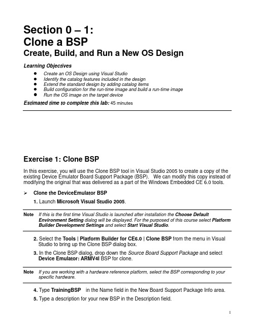
Section 0 – 1:Clone a BSPCreate, Build, and Run a New OS DesignLearning ObjectivesCreate an OS Design using Visual StudioIdentify the catalog features included in the designExtend the standard design by adding catalog itemsBuild configuration for the run-time image and build a run-time imageRun the OS image on the target deviceEstimated time to complete this lab:45 minutesExercise 1: Clone BSPIn this exercise, you will use the Clone BSP tool in Visual Studio 2005 to create a copy of the existing Device Emulator Board Support Package (BSP). We can modify this copy instead of modifying the original that was delivered as a part of the Windows Embedded CE 6.0 tools. Clone the DeviceEmulator BSP1. Launch Microsoft Visual Studio 2005.Note If this is the first time Visual Studio is launched after installation the Choose Default Environment Setting dialog will be displayed. For the purposed of this course select Platform Builder Development Settings and select Start Visual Studio.2. Select the Tools | Platform Builder for CE6.0 | Clone BSP from the menu in VisualStudio to bring up the Clone BSP dialog box.3. In the Clone BSP dialog, drop down the Source Board Support Package and selectDevice Emulator: ARMV4I BSP for clone.Note If you are working with a hardware reference platform, select the BSP corresponding to your specific hardware.4. Type TrainingBSP in the Name field in the New Board Support Package Info area.5. Type a description for your new BSP in the Description field.6. Type TrainingBSP in the Platform Directory field.7. Type GeneriCo in the Vendor field.8. Type 1.0 in the Version field.9. Click the Clone Button. The Clone BSP tool will create a new Board Support Packagebased on the DeviceEmulator Board Support Package.10. Acknowledge the Clone BSP success message by selecting OK.11. Open the C:\WINCE600\PLATFORM\TrainingBSP\FILES folder using WindowsExplorer.Note The labs in this course refer to the default installation path for OS Build Tree, which is “C:\WINCE600”. If your path is something other than the default you will need to make theadjustment anytime the path is noted.12. Rename the deviceemulator-preri.bat file to trainingbsp-preri.bat.Note The previous step was necessary due to a bug in the Clone BSP tool. It is only necessary if the source BSP contains certain build related batch files in the FILES directory. This is notcommon, but is the case with the DeviceEmulator BSP. Failure to make the change will causea build error in a later step.The DeviceEmulator Board Support Package has now been cloned into a new Board Support Package called TrainingBSP. The TrainingBSP Board Support Package will be used in the remaining labs.Exercise 2: Create, build and run the OS designIn this exercise you will create an OS design, and then customize that design by adding components from the catalog and build the result. You will run the OS design on the Device Emulator.This OS design will be used in other labs and will be a suitable platform for running a variety of Windows CE applications.You will learn how to:Create an OS DesignSet up the build configuration for your OS run-time imageBuild an OS run-time imageRun the OS Design on the Device EmulatorCreate an OS design1. Select File | New | Project… from the Visual Studio menu.2. Select the Platform Builder for CE 6.0 project type in the New Projectdialog.3. Select OS Design under Visual Studio installed templates.4. Type TrainingOSDesign in the Name field. The solution name willdefault to TrainingOSDesign as well.5. Click OK. Visual Studio will launch the Windows Embedded CE6.0 OS Design Wizard.6. Click Next.7. In the list of available BSPs, select TrainingBSP: ARMV4I and click Next.8. From the list of available design templates, select PDA Device and clickNext.9. From the list of available design variants, select Mobile Handheld andclick Next. The Applications & Media configuration window willappear.10. Deselect .NET Compact Framework 2.0 and ActiveSync and clickNext. The Networking & Communications configuration window willappear.11. Deselect TCP/IPv6 Support.12. Deselect Personal Area Network (PAN). This will deselect Bluetoothand IrDA.13. Click Next, and then Finish to complete the Windows Embedded CE6.0 Design Wizard.Note The wizard creates the initial configuration for your OS design. We will have the opportunity to make further changes to the OS design after completing the wizard.14. Click Acknowledge on the Catalog Item Notification dialog.On completion, Visual Studio will display your OS design project. The SolutionExplorer tab should be active and show your new TrainingOSDesign project inyour TrainingOSDesign Solution.Inspect the OS Catalog15. Click on the Catalog Items View tab to display the Catalog.16. Click on the Filter drop down box in the upper left hand corner of theCatalog Items View. Observe the different filtering options. The filtercontrols the items that are displayed in the catalog. Ensure that AllCatalog Items in Catalog is selected.17. Observe the selection boxes and icons in the catalog by expanding thenodes. Selection boxes with a green check mark indicate an item thatwas specifically selected as a part of the OS design. Selection boxeswith a green square indicate an item that was brought in to the OSdesign as a dependency. Selection boxes that are not marked indicateitems that are not included in the OS design but are available to beadded.18. Locate a catalog item with a green square in its checkbox.19. Right click on the catalog item and choose Reasons for Inclusion ofItem. The Remove Dependent Catalog Item dialog box displays thecatalog items you selected that caused this catalog item to automatically be included in the OS design.20. Close the Remove Dependent Catalog Item dialog box.21. Expand the Core OS | CEBASE | Applications – End User | Active Syncnode in the catalog.22. Right click on either of the ActiveSync system cpl items (or double click)and select Display in Solution View. The view will change to theSolution Explorer tab. The subproject containing the ActiveSynccomponent is displayed.This is a great way to navigate the source code that is available as partof Windows Embedded CE 6.0.Add support for Internet Explorer 6.0 Sample Browser catalog item23. Select the Catalog Items View tab to display the OS design catalog.Note If the filtering option was not set to All Catalog Items in Catalog, you would not see catalog items that were not already included in the OS design.24. Enter the text Internet Explorer 6.0 Sample into the search text box tothe right of the filter button. Press Enter or click the green arrow. Thepath Core OS | CEBASE | Internet Client Services | Browser Application| Internet Explorer 6.0 for Windows Embedded CE – StandardComponents should be expanded.Note Depending on where you are currently located in the catalog, you may have to restart the search from the top.25. Select, to check, the Internet Explorer 6.0 Sample Browser catalogitem.Add support for managed code development to your OS design26. Enter the text ipconfig into the Search box and press Enter. TheNetwork Utilities (IpConfig, Ping, Route) will be highlighted.Note Again, depending on node selected when starting a search in the catalog, you may have to restart the search from the top.27. Add the Network Utilities to your design by selecting the component.28. Enter the text wceload into the Search box and press Enter. The CABFile Installer/Uninstaller component will be highlighted. This is due tothe fact that the SYSGEN name for the component is “wceload”.29. Add the Cab File Installer/Uninstaller utility to your OS design.30. Enter the text sysgen_dotnetv2_support into the Search box andpress Enter. The OS Dependencies for .NET Compact Framework2.0 component will be highlighted.31. Add the OS Dependencies for .NET Compact Framework 2.0 to yourOS design.Note There are two separate components in this category. Be sure you select the one that does NOT have the – Headless modifier in its description.Build the OS run-time image32. Select Build | Configuration Manager… from the Visual Studio menuto bring up the Configuration Manager dialog box.33. Select TrainingBSP ARMV4I Debug from the Active solutionconfiguration drop down box and then close the dialog box.34. Select the Solution Explorer view by selecting the Solution Explorertab.35. In the Solution Explorer window, right click on theTrainingOSDesign project (not the Solution node) and chooseProperties. This will launch the Property Pages dialog for your OSdesign.36. Expand the Configuration Properties tree and click on the BuildOptions node.37. Ensure the following build options are set:Enable eboot space in memoryEnable kernel debuggerEnable KITLEnable profiling38. Select OK39. Select Build | Build TrainingOSDesign from the Visual Studio menu.Note This will take several minutes to complete depending on the capabilities of your development system. The following steps for configuring connectivity may be accomplished while building.Configure connectivity options40. Select Target | Connectivity Options… from the Visual Studio menu.The Target Device Connectivity Options dialog will appear showingthe Kernel Service Map configuration for the CE Device namedconnection.41. Select Device Emulator (DMA) from the Download drop down box.42. Select Device Emulator (DMA) from the Transport drop down box.43. Select KdStub from the Debugger drop down box.Change the emulator configurationThe emulator has a number of configurable options. We will modify it to use a larger screen resolution and to enable network communications.44. Next to the Download drop down menu click Settings.45. Select the Display tab in the Emulator Properties dialog box.46. Change the Screen width to 640 pixels and the Screen height to 480pixels.47. Select the Network tab in the Emulator Properties dialog box.48. Check the box beside Enable NE2000…49. Click on OK50. Select Apply to save the new device configuration.51. Select Close to close the dialog box.Note The build must complete before moving on to the next step.Test your OS run time image on the Device Emulator52. Select Target | Attach Device from the Visual Studio menu.Visual Studio will start the Device Emulator with your OS run time image design. The download will take a short time to complete. You will be able to interact with the emulator and test the features of your new OS design. Congratulations, you have successfully built and run your first Windows Embedded CE 6.0 OS design!If you are continuing with the next Hands-On Lab, keep your emulator image running.Section 0 – 2:Static and Dynamic LibrariesObjectivesCreate simple static libraryLink the static library with a dynamic libraryLink the dynamic library with an executableEstimated time to complete this lab:45 minutesExercise 1: Create a static library (LIB)In this exercise you will create a static library with routines that you will later link to when you build a dynamic library and an executable.Note This exercise involves a bit of typing; if you perfer you may copy the text from the Student files. Create a static library subproject1. Select Project | Add New Subproject… from the Visual Studio menu.This will bring up the Windows CE Subproject Wizard.2. Select the WCE Static Library template.3. Set the Subproject name to Power_Status and click Next.4. Check the Precompiled header box.5. Click Finish.6. Configure the Power_Status subproject to be excluded from theimage and always build and link as debug. (In Solution ExplorerView, right click the TrainingOSDesign and select the Properties)Create files7. Right click on the Power_Status subproject in the Solution Explorerand select Add | New Item…8. Select the Code category, the C++ File (.cpp) template, and then typePower_ON_OFF in the name field.9. Click on Add to add the new file.10. Right click on the Power_Status subproject in the Solution Explorerand select Add | New Item…11. Select the Code category, the Header File (.h) template, and thentype Power_Status in the name field.12. Click on Add to add the new file.13. Using the Solution Explorer, locate the Power_ON_OFF.cpp file in thePower_Status subproject and open it.14. Add the following code to the Power_ON_OFF.cpp file:#include"stdafx.h"LPCTSTR g_StrOn = L"Power is on";LPCTSTR g_StrOff = L"Power is off";LPCTSTR PowerOn(){return g_StrOn;}LPCTSTR PowerOff(){return g_StrOff;}15. Save and close Power_ON_OFF.cpp.16. Expand the Include files node in the Power_Status subproject andopen stdafx.h17. Add an include for <windows.h> as follows:// TODO: reference additional headers your program requires here#include<windows.h>18. Save and close stdafx.h.19. Using the Solution Explorer, locate the Power_Status.h file in thePower_Status subproject and open it.20. Add the following to Power_Status.h:extern LPCTSTR PowerOff(void);extern LPCTSTR PowerOn(void);21. Save and close Power_Status.h.Build the library22. Right click the Power_Status subproject in the Solution Explorer andselect Build.Exercise 2 Create a dynamic library (DLL)In this exercise you will create a dynamic library that will link with the static library you created previously.Note This exercise involves a bit of typing; if you perfer you may copy the text from the Student files.Create the dynamic library subproject1. Select Project | Add New Subproject… from the Visual Studio menu.2. Select the WCE Dynamic-Link Library template.3. Set the Subproject name to ScanBarcode and click Next.4. Select A simple Windows Embedded CE DLL subproject and clickFinish.5. Configure the ScanBarcode subproject to be excluded from theimage and always build and link as debug.Edit source files for DLL project6. In the Solution Explorer, right-click on the ScanBarcode subproject,and then select Add | New Item…7. Select the Code category, the Header File (.h) template, and then typeScanBarcode in the name field.8. Using the Solution Explorer, open the ScanBarcode.h file from theScanBarcode subproject.9. Add the following code to the ScanBarcode.h file:#include<windows.h>EXTERN_C LPCTSTR ScanBarcode(void);EXTERN_C LPCTSTR ScanPowerOff(void);EXTERN_C LPCTSTR ScanPowerOn(void);10. Using the Solution Explorer, open the ScanBarcode.def file from theParameter files node in the ScanBarcode subproject.11. Add the following to the DEF file:LIBRARY ScanBarcodeEXPORTSScanPowerOffScanPowerOnScanBarcode12. Save and close ScanBarcode.def.13. Using the Solution Explorer, open the ScanBarcode.cpp file from theScanBarcode subproject.14. Add an include statement for Power_Status.h as follows:// ScanBarcode.cpp : Defines the entry point for the DLL application.//#include"stdafx.h"#include"Power_Status.h"BOOL APIENTRY DllMain( HANDLE hModule,DWORD ul_reason_for_call,LPVOID lpReserved){return TRUE;}15. Add the following code snippet to ScanBarcode.cpp after the inclusionof Power_Status.h.LPCTSTR g_StrScan = L"123456789ABC";EXTERN_C LPCTSTR ScanBarcode(void){return g_StrScan;}EXTERN_C LPCTSTR ScanPowerOn(void){return PowerOn();}EXTERN_C LPCTSTR ScanPowerOff(void){return PowerOff();}16. Save and close ScanBarcode.cpp.Link to static library17. Right click on the ScanBarcode subproject node in the SolutionExplorer, and then select Open. The ScanBarcode SOURCES filwill open.18. Locate the section of the file containing TARGETLIBS.19. Add a reference to the Power_Status.lib static library by modifying thissection as follows:TARGETLIBS= \$(_PROJECTROOT)\cesysgen\sdk\lib\$(_CPUINDPATH)\coredll.lib \$(PBWORKSPACEROOT)\Power_Status\obj\$(_CPUINDPATH)\Power_Status.lib \Note The trailing backslash characters on each line are line continuation characters. Ensure that there is no white space after them. Also, ensure that there is a blank line following the last line.20. Add the path to directory containing the Power_Status.h header file byadding the following to the bottom of the SOURCES file:INCLUDES= \$(PBWORKSPACEROOT)\Power_Status \Note Ensure that there is at least one blank line prior to the line containing the INCLUDES directive.This ensures that there are no line continuation characters prior to this statement that are still in effect.21. Save and close the SOURCES file.22. Right click on the ScanBarcode subproject in the Solution Explorerand select Properties.23. Select the C/C++ tab and observe the Include Directories entry.Notice that the directory you just added with the INCLUDES directivein the SOURCES file is listed here.24. Select the Link tab and observe the Additional Libraries entry.Notice that the library you just added with the TARGETLIBS directivein the SOURCES file is listed at the end of this line.Note The SOURCES file itself controls the build rules for the subproject. The graphical user interface shown here provides an alternate way to view and modify this file.25. Select Cancel to close this dialog without making any changes.Build the library26. Right click the ScanBarcode subproject in the Solution Explorer andselect Build.Exercise 3 Create an executable (EXE)In this exercise you will create an executable that uses functionality from the dynamic library you just created.Adding existing application subproject1. Copy the BarcodeDllTest subproject from the Student files to your OSdesign atC:\WINCE600\OSDesigns\TrainingOSDesign\TrainingOSDesign.2. Right click on the Subprojects node in the Solution Explorer and selectAdd Existing Subproject.3. Select the BarcodeDllTest.pbpxml file from the BarcodeDllTestfolder.4. Configure the BarcodeDllTest subproject to be excluded from theimage and always build and link as debug.Add reference to dll5. Right click on the BarcodeDllTest subproject in the Solution Explorerand select Open.6. Add the following to the bottom of the file:INCLUDES= \$(PBWORKSPACEROOT)\ScanBarcode \Note Ensure that there is a blank line preceding the INCLUDES directive. Ensure there is no whitespace after the trailing backslashes.7. Locate the TARGETLIBS directive and add a reference toScanBarcode.lib as follows:TARGETLIBS= \$(_PROJECTROOT)\cesysgen\sdk\lib\$(_CPUINDPATH)\coredll.lib \$(PBWORKSPACEROOT)\ScanBarcode\obj\$(_CPUINDPATH)\ScanBarcode.lib \Note Ensure that there is a blank line after the line containing ScanBarcode.lib. Ensure there is no white space after the trailing backslashes.8. Save and close the sources file.9. Right click on the BarcodeDllTest subproject and select Build.Run the BarcodeDllTest application10. Launch BarcodeDllTest.exe using Target | Run Programs from theVisual Studio menu.11. The BarcodeDllTest.exe application will present the following userinterface. You can exercise it by clicking on the various buttons.This simple application makes calls into the linked Scanbarcode.dll dynamic library, which includes functionality from the Power_Status.lib static library. You may wish to set breakpoints on functions in these modules and view the call stacks to see how they are eventually called from the application.Section 1:Integrating a Device DriverEstimated time to complete this lab: 30 minutesExercise 1: Integrate barcode scanner driver into BSPThe purpose of this exercise is to integrate a driver into the BSP. In this exercise you will Add the driver subdirectory containing the driver source code to the BSPAdd the appropriate bib entry to cause the driver to be included in the OS image Add the appropriate registry entries to cause the drive to be loaded at bootUpdate the BSP catalog file to support the new driverBuild a debug OS run-time image that we will use in future labsAdd driver source code to BSP directory1. Detach from the Emulator if connected.2. Copy the BARCODE directory from Student files to theC:\WINCE600\PLATFORM\TrainingBSP\SRC\DRIVERS directory.3. Double click the C:\WINCE600\PLATFORM\TrainingBSP\src\driversnode in the Solution Explorer. This will open the Dirs file.4. Add the following line to the end of the Dirs file directly after the# @CESYSGEN ENDIF CE_MODULES_DEVICE line:barcode \5. Save and close the Dirs file.Add Driver to image6. Open the platform.bib file in the Parameter Files node of theTrainingBSP in the Solution Explorer.7. Add the following lines near the top of platform.bib as the first entryin the MODULES section.IF BSP_BARCODEbarcode.dll $(_FLATRELEASEDIR)\barcode.dll NK SHK ENDIFWhen you are done, the top of the file should look similar to the following:;; Copyright (c) Microsoft Corporation. All rights reserved.;;; Use of this source code is subject to the terms of the Microsoft end-user; license agreement (EULA) under which you licensed this SOFTWARE PRODUCT.; If you did not accept the terms of the EULA, you are not authorized to use; this source code. For a copy of the EULA, please see the LICENSE.RTF on your; install media.;MODULES; Name Path Memory Type; -------------- ---------------------------------- -----------IF BSP_BARCODEbarcode.dll $(_FLATRELEASEDIR)\barcode.dll NK SHKENDIF; @CESYSGEN IF CE_MODULES_DISPLAYIF BSP_NODISPLAY !TrainingBSP_lcd.dll $(_FLATRELEASEDIR)\TrainingBSP_lcd.dll NK SHK; @CESYSGEN IF SHELLW_MODULES_GX; @XIPREGION IF MISC_TRAININGBSP_BIB8. Save and close the file.Add registry settings9. Open the file Platform.reg from the Parameter Files node of theTrainingBSP using the Solution Explorer.10. Right click on the [HKEY_LOCAL_MACHINE\Drivers\BuiltIn] keyand add a new key with the name Barcode.11. Add a String Value to the Barcode key with the name Dll and valueBarcode.dll.12. Add a String Value to the Barcode key with the name Prefix andvalue BAR.13. Save and close the file.Add driver to the catalog14. From the Visual Studio menu, select File | Open | File … and navigateto the C:\WINCE600\PLATFORM\TrainingBSP\CATALOG folder.15. Change the file mask to show Files of type: All Files (*.*)16. Open the TrainingBSP.pbcxml file.Note If no nodes are visible underneath Catalog in the Catalog Editor, click the Show All Catalog Files button.17. Expand the catalog tree to show the Device Drivers node.18. Right click on the Device Drivers node and select Add Catalog Item.The new item will be placed in the Third Party node.19. Set the Description field to Barcode Scanner.20. Set the Title field to Barcode Scanner.21. Set the Unique Id field to Item:GeneriCo:BarcodeScanner.22. Set the Additional Variables field to BSP_BARCODE.23. Set the Modules field to barcode.dll.24. Save and close the file.Add barcode scanner driver to image25. Switch to the Catalog Items View.26. Expand the TrainingBSP node under Third Party.Note Ensure that the Filter option is set to All Items in the Catalog. The Filter option is a drop down box in the upper right hand corner of the Catalog Items View.27. Select the Barcode Scanner item under Device Drivers. Refresh theCatalog View if necessary to see the Barcode Scanner.28. Select Build | Advanced Build Commands | Build Current BSPand Subprojects from the Visual Studio menu.Verify integration using Image Viewer29. Open the NK.bin file located in the flat release directory using VisualStudio. This will bring up the Run-Time Image Viewer.30. Click on the (All Files) node in the Image Explorer. This shows allfiles that are built into the OS run time image.31. Verify that barcode.dll is listed.32. Verify that the [HKLM\Drivers\BuiltIn\Barcode] key exists under theregistry node.33. Close the Image Viewer.Build debug OS image34. Select Build | Configuration Manager… using the Visual Studiomenu.35. Set the Active solution configuration to TrainingBSP ARMV4IDebug.36. Select Build | Build Solution using the Visual Studio menu. This willbuild a debug configuration that we will use in future labs.Section 2:Debugging the Scanner Device Driver ObjectivesUnderstand driver interaction with applicationUse kernel debugger to investigate call stackEstimated time to complete this lab: 30 minutesExercise 1 Application and Driver IntegrationIn this exercise you will add an application that communicates with the barcode scanner device driver. You will exercise the functionality of the driver and function call tree that results when the application calls into the driver.Add BarcodeTest1 application subproject to your OSDesign1. Copy the BarcodeTest1 folder from your Student files toC:\WINCE600\OSDesigns\TrainingOSDesign\TrainingOSDesign.2. Right click on the Subprojects node in the Solution Explorer and selectAdd Existing Subproject...3. Add the BarcodeTest1 subproject to your OS design.4. Configure the BarcodeTest1 subproject to be excluded from theimage and always build and link as debug.5. Right click on the BarcodeTest1 subproject in the Solution Explorerand select Build.Run test application on OS image6. Attach the emulator by selecting Target | Attach Device from the VisualStudio menu.Note This lab uses an updated version of the OS run time image. You will need to first detach from the existing emulator instance if it is still running.7. Open the BarcodeTest1.cpp file in the BarcodeTest1 subproject usingthe Solution Explorer.8. Set a breakpoint on the call to DeviceIoControl().9. Run the BarcodeTest1 application using Target | Run Programs…from the Visual Studio menu. The debugger will halt execution at thebreakpoint.10. Select Debug | Windows | Call Stack from the Visual Studio menu toshow the call stack. This window shows the sequence of calls thatresulted in the statement containing the breakpoint. You can doubleclick any of the calling functions to view the source code file containingeach function.Note The source code for the functions listed in this window is only available if you have installed the Shared Source. Only the disassembly view is available if the source code is not installed.11. Step through the application by pressing F10 through completion.Add additional functionality to test application and retest12. Locate the comment //Turn on power and add the following functioncall:Code:// Turn on powerDeviceIoControl(hBARPort, BARCODE_IOCTL_POWER_ON, NULL, 0, NULL,0, &dwNumBytesRead, NULL);13. Locate the comment //Check to make sure power is on and add thefollowing function call:Code:// Check to make sure power is onDeviceIoControl(hBARPort, BARCODE_IOCTL_QUERY_POWER_STATE,NULL,0, &dwResult, sizeof(DWORD), &dwNumBytesRead, NULL);_tprintf(_T("Power Status = %d.\n"),dwResult);14. Right click on the BarcodeTest1 subproject and select Build.15. Run the BarcodeTest1 application using Target | Run Programs…from the Visual Studio menu. The debugger will halt execution at thebreakpoint.16. Press F517. Observe debug messages in the Output window similar to thefollowing:Test BAR1: driver open/close.Barcode.DLL: +BAR_OpenBarcode.DLL: -BAR_OpenCreateFile returned a valid handle.Barcode.DLL: +BAR_IOControlBarcode.DLL: IOCTL - Set Power ManagementBarcode.DLL: -BAR_IOControl。
嵌入式处理器+网卡芯片RTL8019

——ARM与C/OS-Ⅱ
基本概念及设计方法
1
一、嵌入式系统硬件基础
冯· 诺依曼体系结构和哈佛体系结构
CISC与RISC
影响CPU性能的因素
存储器系统
I/O接口
2
典型嵌入式系统基本组成-硬件
电源 模块
时钟
外围电路 微处理器
Flash
RAM
MPU
复位
ROM
14
一个典型的USB通讯系统
通用系统模型 HOST系统
PC机中的情况
应用软件+驱动程序 Ms.Win+接口芯片
嵌入式系统应用
驱动代码+嵌入式处理 器+HOST芯片
HUB
DEVICE D U盘
HUB
其他 U盘
HUB
其他
DEVICE
数据采集器
数据采集器
15
二、嵌入式系统软件基础
操作系统的分类 嵌入式实时操作系统
例如,很多基于微处理器的产品采用前后台系统设计,如微波炉 、电话机、玩具等。从省电的角度出发,平时微处理器处在停机状态 ,所有的事都靠中断服务来完成。
20
前后台系统(后台循环、前台中断)
后台 ISR 前台
时间
ISR
ISR
21
代码的临界区
代码的临界区也称为临界区,指处理时不可分割的代码。 一旦这部分代码开始执行,则不允许任何中断打入。
大家生活中常见的与USB有关的东西有:
U盘、移动硬盘、无驱型的MP3(U盘) USB接口的键盘、Mouse、打印机、数码相机……
即插即用,热插拨,系统不需重启便可工作,且易于扩展 (127个)
ARM嵌入式Windows CE实践教程

第6章 Windows CE驱动程序实验6.1 WINCE驱动程序模型基于WINCE的驱动程序有两种模型,它们是本机设备驱动程序和流接口驱动程序。
不同的驱动模型只能通过它们支持的软件接口来区别,而不是它们所适用的设备,驱动程序模型决定了指定驱动程序输出的软件接口。
WINCE是可移植的,将它移植到目标平台上,必须为在平台上已建立的设备提供驱动程序。
一些类型的设备,如键盘、显示器等,对操作系统都有一定的接口。
因为这些接口是专门用于WINCE的,所以这类设备的驱动程序称作本机设备驱动程序。
本机驱动设备驱动程序适于集成到基于WINCE平台的设备,通用LED驱动和电源驱动就是这样的例子。
通用LED驱动由nleddrv.lib 连接,电源驱动由battery.lib连接。
还有一些样本本机驱动程序,例如显示驱动程序和键盘驱动程序,他们表现在一个DLL的文件上由GWES统一加载和管理。
因为本机设备驱动程序通常与基于WINCE的平台有着紧密的连接,而每种本机设备驱动程序都有精确的和特殊的目的,微软提供了定制接口的方式来支持内部设备驱动程序,也就是说绝大多数的开发人员不需要编写本机设备驱动程序。
但是把WINCE定制到新平台的原始设备制造商(OEM)除外,他们可以创建自己的本机设备驱动程序,也可以将微软的本机设备驱动程序的例子移植到他们基于WINCE的平台上。
本机设备驱动程序总是在基于WINCE的平台启动时加载。
流接口驱动程序是一般类型的设备驱动程序。
流接口驱动程序表现为在用户一级的动态链接库DLL,用来实现一组固定的函数称为流接口函数,这些流接口函数使得应用程序可以通过文件系统访问这些驱动程序。
流接口驱动程序几乎支持任何类型的可以连接到基于WINCE的平台外部设备。
同时用户还可以定制出不支持任何外围设备的流接口驱动程序,这些驱动只是提供某些服务。
6.2 本机设备驱动程序的系统结构对于本机设备驱动程序,PB提供了一些驱动程序的样本。
Wince6.0安装指南
实验四搭建WinCE 6.0 开发环境一.课时安排:4学时二.实验目的通过本实验掌握Windows CE 6.0 开发环境Platform Builder 的安装。
三.实验设备(1)硬件:PC机一台(2)软件Visual Studio 2005Windows CE 6.0安装软件四.实验内容安装VS2005安装MSDN(可选)安装Windows CE 6.0(Platform Builder for Windows CE 6.0)安装Windows CE 6.0 R2安装Windows CE 6.0 R3五.实验原理在Windows CE 6.0 之前,Windows CE 的开发环境都是当做一个独立的软件进行安装,安装成功之后用户可以看到一个名为Platform Builder for CE4.2/5.0 的工具,用户就直接使用这个IDE 来定制OS。
这种情况到Windows CE6.0 后做了较大改变,在安装Windows CE 6.0 之前必须安装VS2005,在顺利安装完VS2005 以及Windows CE 6.0 后,可看到对应的开发工具PlatformBuilder for Windows CE 6.0 当做一个插件集成到VS2005 的开发环境中。
本设备用到的Windows CE 6.0 R3 其实是Windows CE 6.0 的最新版本,这之前的版本号是Windows CE 6.0 R2。
通过以上知识点的了解就可以明白接下来安装开发环境各步骤先后顺序的关系。
六.实验步骤1.开发应用程序需安装软件及更新(软件列表见“WinCE 6.0下载列表”)Visual Studio 2005Visual Studio 2005 SP12.开发Windows Embedded CE 6.0操作系统需依次安装软件及更新开发WinCE 6.0系统,除按上面次序安装VS2005外,还需要按次序安装以下软件及补丁,由于安装路径对程序开发有一定的影响,为保持统一,减少不必要的麻烦,本文假定所有安装都是按照默认路径。
嵌入式组态王Wince运行环境的安装与演示过程

嵌入式组态王在Wince 平台下的安装与演示过程陕西威蓝工业自动化有限公司2011.07.201.前期准备工作:(1)注册MSCOMM32.OCX控件:打开组态王使用说明文档,把MSCOMM32.OCX控件拷贝到PC计算机的C 盘目录下,再打开开始运行cmd,进入命令环境在C:\Documents and Settings\su>下编辑cd .. 直至切换到C:\> ,如下图然后,编辑regsvr32 MSCOMM32.OCX,注册成功,如下图所示:(2)串口选择RS232模块插入计算机后,在计算机设备管理器里确认端口,本例子使用串口5,如下图所示:打开组态王使用说明文档里kingview com.exe可执行文件,在串口设置中选择COM5,并点击“请选择串口”打开串口,如下图所示:(3)板子连线说明:电源接直流5V电源,鼠标和USB线接USB2口(注意USB线上的三角箭头端与板子USB2三角箭头端对应),串口线接板子的COM1口(串口线三角箭头端靠网口那端),具体接法如下图所示:2.安装组态王嵌入版运行系统:第一步:将安装有组态王嵌入版开发系统的PC机和嵌入式系统连接在同一个局域网的同一个网段中。
(如果采用网线直接将PC机和嵌入式系统设备连接的话,需要使用交叉网线)。
第二步:上电启动预先安装在系统上的WinCE系统,设置WinCE上的网络和拨号连接,给这个设备分配一个IP地址。
第三步:在嵌入式平台NandFlash目录下,建立一个文件夹kingview。
第三步:在PC机下将组态王嵌入版安装目录的ARMV4文件夹里面的全部内容(除了Driver文件夹)拷贝到U盘,再将此内容全部拷贝到嵌入式平台新建的kingview目录,同时在kingview目录下新建一个文件夹project。
第四步:在kingview目录下打开KV_FTP_SERVER.EXE,此时该界面显示IP地址:如192.168.1.82第五步:打开PC机嵌入式组态王开发环境,点击主菜单中“工具\网络远程部署操作”,弹出远程部署操作对话框如下图所示:第六步:在远程站点输入嵌入式平台的IP地址,并点击连接按钮,直至连接成功,如下图所示:第七步:点击远程部署操作的安装,输入“本地”和“远程”的安装路径,“本地”一般系统默认能找到,在“远程”框输入\NandFlash\kingview,点击安装嵌入版,在安装过程中,嵌入式平台会出现提示,点击OK,跳过,直至安装成功。
最新winCE 嵌入式 常规的应用开发步骤讲学课件

在EVC中:通过WCE Configuration工具栏,可选择在模 拟器或设备调试应用程序
在Visual Studio中,可通过Device工具条选择模拟器环境 和设备环境。 模拟器缺点:只是模拟CE可运行的部分硬件.很多外设都需要 真实硬件支持。
第一、 代码签名可使开发人员和发布人员确保其基于Windows Mobile平台的Smartphone手机上的应用程序在传递和执行的时候 是安全可信的。 Smartphone支持3种授权模式:
1、特权信任(Privilege Trust) 2、非特权信任(Unprivilege Trust) 3、不被信任(Untrusted) 第二、代码签名可确保应用程序在传递和分发时的完整性和一致 性。 应用程序的代码签名有微软的两家合作伙伴—Verisign和 Betrusted
介绍ActiveSync
ActiveSync提供了一种支持,用来同步基于桌面 Windows系统和基于的便携式系统间的数据, 它使用时间标记(stamps)和用户参数来跟踪两个系统 间的数据改变,并传送相应的数据使得每个系统上的 数据都是最新的,过时的或者冗余的数据会被删除。
ActiveSync支持USB, 红外,调制解调器, 以及 Ethernet 等多种连接。
价格 Price
海尔集团采用需求导向的定价法,即以目标市场 的消费者的需求为定价的基础。海尔集团同时采 用差别定价法,在低端市场,采用价值定价法, 即用相对的低价出售高品质的产品或服务,而非 牺牲质量的前提下降低成本;在高端市场,通常 采取撇脂定价,即将价格定得相对于产品对大多 数潜在顾客的经济价值来讲比较高,以便从分额 虽小但价格敏感性较低的消费者细分中获得利润。
ARM嵌入式WINCE实践教程_图文.

ARM 嵌入式WINDOWS CE实践教程ARM 嵌入式WINDOWS CE实践教程 CVT-PXA270华中科技大学国家电工电子教学基地武汉创维特信息技术有限公司ARM 嵌入式WINDOWS CE实践教程前言《ARM 嵌入式WINDOWS CE实践教程》是ARM 嵌入式技术系列教程之一。
该教程教材采用华中科技大学和武汉创维特信息技术有限公司联合研制的CVT-PXA270系列嵌入式教学实验系统作为教学实践平台。
Windows CE 嵌入式操作系统是目前嵌入式主流操作系统之一,它以超强的性能、友好的Windows 人机界面以及标准化、可视化的软件开发过程被越来越多地使用在手机、PDA 等产品中,本书结合XSCALE 嵌入式处理器的特点,介绍了在其上进行Windows CE开发的过程和方法。
本书详细地讲解了Windows CE BSP开发平台Platform Build 5.0的建立过程、Windows CE BSP板级支持包的开发、驱动程序的设计以及基于Embedded Visual C++嵌入式Windows CE应用程序的设计和开发等,内容覆盖Windows CE开发的全过程,它不仅可以作为嵌入式Windows CE开发的初学者作为实践教程,而且对于Windows CE 开发人员也有一定的参考价值。
ARM 嵌入式WINDOWS CE实践教程目录第1章安装Windows CE BSP........................................11.1 安装WINDOWS CE5.0..............................................................................................11.2 安装WINDOWS CE 5.0 BSP......................................................................................2第2章 Windows CE 内核定制实验.................................. 42.1 创建和编译新项目...................................................................................................... 42.2 运行image 文件........................................................................................................ 172.2.1 设置并建立tftp 服务器.................................................................................. 182.2.2 通过uboot 下载nk.nb0................................................................................... 18第3章 WINCE和桌面系统通讯实验........................... 243.1 硬件连接.................................................................................................................. 243.2 WINCE端设置.......................................................................................................... 243.3 activeSync安装.......................................................................................................... 243.4 USB驱动程序安装.................................................................................................... 253.5 通讯.......................................................................................................................... 27第4章 Windows CE 应用程序实验.............................. 284.1 下载并安装Microsoft eMbedded Visual C++4.0....................................................284.2 建立HelloWorld 工程................................................................................................ 314.3 下载并运行HelloWorld............................................................................................ 354.4 调试HelloWorld....................................................................................................... 38第5章 Windows CE 多媒体播放实验.......................... 465.1 安装媒体播放器...................................................................................................... 465.2 建立WINCE 和桌面系统之间的通讯连接............................................................. 485.3 拷贝视频文件到WINCE My Documents................................................................495.4 播放视频文件.......................................................................................................... 49ARM 嵌入式WINDOWS CE实践教程第6章 Windows CE 驱动程序实验.............................. 516.1 WINCE驱动程序模型.............................................................................................. 516.2 本机设备驱动程序的系统结构.............................................................................. 526.3 流接口驱动程序的系统结构.................................................................................. 526.3.1 设备管理器................................................................................................... 526.3.2 设备文件名................................................................................................... 546.3.3 流接口驱动程序入口函数........................................................................... 546.4 流接口驱动程序开发.............................................................................................. 576.5 流接口驱动程序调用实例...................................................................................... 676.6 运行.......................................................................................................................... 68第7章 Windows CE 接口实验..................................... 697.1 CVT-PXA270 跑马灯实验...................................................................................... 697.2 CVT-PXA270 数码管实验...................................................................................... 847.3 CVT-PXA270 进程编写实验.................................................................................. 907.4 CVT-PXA270 多线程实验...................................................................................... 927.5 CVT-PXA270 步进电机实验.................................................................................. 947.6 CVT-PXA270 LCD 控制实验.............................................................................1027.7 CVT-PXA270 录放音实验.................................................................................1047.8 CVT-PXA270 简单多媒体实验......................................................................... 1057.9 CVT-PXA270 读写文件实验............................................................................. 106第8章 Windows CE 以太网驱动程序实验................ 1108.1 CVT-PXA270网卡................................................................................................ 1108.2 LAN91C111网卡驱动程序中断处理................................................................... 1108.3 LAN91C111网卡驱动程序硬件地址................................................................... 1118.4 网络连接的添加................................................................................................... 1118.6 网络驱动程序编译和测试................................................................................... 114第9章 GPS模块导航实验........................................ 1159.1 系统简介............................................................................................................... 1159.2 系统设置............................................................................................................... 1159.3 硬件设置............................................................................................................... 1169.4 实验步骤............................................................................................................... 118ARM 嵌入式WINDOWS CE实践教程第1章安装Windows CE BSP1.1 安装WINDOWS CE 5.0本节讲述如何安装Windows CE 5.0以及Platform Builder。
- 1、下载文档前请自行甄别文档内容的完整性,平台不提供额外的编辑、内容补充、找答案等附加服务。
- 2、"仅部分预览"的文档,不可在线预览部分如存在完整性等问题,可反馈申请退款(可完整预览的文档不适用该条件!)。
- 3、如文档侵犯您的权益,请联系客服反馈,我们会尽快为您处理(人工客服工作时间:9:00-18:30)。
阿尔泰科技ARM8018/19主板WinCE部分说明书北京阿尔泰科技发展有限公司Beijing Art Technology Development Co.,Ltd.一.测试主板31、 串口测试 (3)2、 USB及CF接口测试 (7)3、 网口测试 (8)4、 Media测试 (10)二、通过USB建立ARM8018/19与PC机Windows的ActiveSync连接 (11)三、eMbedded VC++ 4.0的安装 (19)四、PC104总线数据采集编程实例(以ART2153卡为例) (32)附录一、WINCE下触摸屏的校准 (44)附录二、NAND FLASH的格式化 (44)附录三、MAC地址的修改 (49)附录四、开机时自动启动用户程序 (51)附录五、如何保存用户的配置 (57)附录六、利用VS2005开发工具编写HelloWorld程序。
(58)附录七、FTP服务 (61)环境要求:(1) windows 操作系统(自行配置)(2) Embeded VC++4.0(免费软件,位于光盘"工具"里)或 VS2005(3) Microsoft ActiveSync(免费软件,位于光盘"工具"->"ActiveSync")一.测试主板准备:先将显示屏连接到主板的VGA接口上,然后用RS-232交叉电缆线将主板的COM0口与PC机连接起来。
测试:1、串口测试(1)打开DNW软件或超级终端,设置串口,点击工具栏“Configuration”下的“Options”,设置串口如下(注意当客户特殊要求COM0口开机后被设置为用户串口时,程序将设置COM0口的串口号为COM2):说明:串口选择为你使用PC机上的串口号点击Serial Port菜单下的connect选项,在DNW窗口的标题栏会出现[COM1,38400bps],表明连接成功。
(2)连接电源,启动主板,在DNW可以看见如下图所示的信息:说明:DNW窗口出现信息说明COM0口已通。
(3) 等待3秒后,将进入启动初始化硬件设备阶段,可以看见如下图所示的一系列信息:(4)当出现下图所示的信息时,主板启动完成:这时在显示屏上我们可以看见如下图所示的开机画面:(5)测试用户RS232串口系统启动后,将PC机的串口连接线与主板的用户串口COM1相连。
首先,打开PC 机的串口调试工具,设置串口号为本PC机的串口号,设置波特率为115200。
然后,在主板的我的设备-->NandFlash下执行COMMApp240320下的COMMApp240320.exe,选择COM端口为“COM3:”,选择BaudRate,可根据用户要求选择,与PC机的一致即可,本例为“115200”,设置完成后单击Open按钮,连接成功则在Status编程框中显示“OpenCOM3:Success!”。
最后,在编辑框中输入要发送的数据,如:“”,单击Send按钮,查看PC机串口调试工具的接收区,显示为“”,则该程序运行正常。
同时,可通过PC机的串口调试工具向主板发送数据,在CommMFC 程序的接收区中将显示出发送的信息。
如下图所示:关闭此应用程序之前先执行“Close”操作关闭串口。
(6)RS485测试RS485测试利用本公司自己设计的DAM3000系列产品的应用程序,测试方法如下:<1> 将DAM3000系列模块通过RS485接口与主板相连,执行“我的设备”Æ“程序”Æ“VS2005”Æ“RS485”Æ“DAM3000M”程序,弹出如下界面:<2> 选择“COM4”,执行“开始查找”,查询到后,在树型框中将显示查找到的DAM3000M系列的模块信息,说明RS485已连接,单击模块信息,可弹出模块的测试界面,如下所示:2、USB及CF接口测试(1)先按照第二章的说明将USB驱动及ActiveSync工具装上,然后将USB线一端接PC机,一端接主板上的USB Device接口,在PC机端将弹出如下图所示的窗口(应该在主板上电后再插入USB线):在上图中选择“No”,然后点击“下一步”,可以看见如下图所示的连接窗口:(2)将USB Host接口插上U盘(USB主接口也可以接USB鼠标或键盘使用),在主板的My Device目录下可以看见如下图阴影部分的内容:U盘(3)在主板上插入CF卡(不能热插拔),在“我的设备”里也可以被认出是一个硬盘。
3、网口测试用交叉网线将PC机和主板连接起来,在PC机端运行命令ping 192.168.1.14 –t(PC机的IP地址需与此地址在同一网段),可看见如下图窗口所示的信息:在主板端的“My Device—>Program Files”路径下双击“Command Prompt”,打开一个主板上的命令窗口,在此窗口中输入ping命令(方法同于在PC机上输入命令,也要求主板与PC机在同一网段),可以在主板上看见如下图所示的信息(考虑到WINCE内核大小,其它一些组建如PDF、WORD、MediaPlay、SQL等,如果客户需要,我们可以在定制内核时加上):在主板端的“我的设备—>控制面板—>网络和拨号连接”路径下双击“DM9CE1”,出现如下图所示的界面:在上图中配置网络的IP地址,然后切换页面到名称服务器,配置DNS(配置主DNS 即可):上述配置完成以后,用户可以直接点击IE浏览器上网。
4、Media测试打开播放软件BetaPlayer,单击“文件—>打开文件”菜单,打开一个视频文件,下图为播放视频文件界面,插上耳机可听到声音:二、通过USB建立ARM8018/19与PC机Windows的ActiveSync连接装有Windows 的嵌入式设备一般可通过USB线、RS232串行线、以太网等通信协议实现与PC机Windows的ActiveSync连接。
在ARM8018/19上,可以通过USB总线实现ARM8018/19与PC机Windows的ActiveSync连接。
实现连接之后,就可以很轻松的传输文件到ARM8018/19的Windows 中,还可以实现eMbedded Visual C++的远程调试功能。
1.安装USB驱动。
用 USB 连接线连接 PC 机和主板,在 PC 机侦测到USB 新硬件后安装驱动即可,(驱动文件位于“工具”里“usb_device_driver”中,若找不到设备,可以参考“安装说明.txt”)。
USB驱动安装好后在设备管理器中会出现“Windows CE USB Devices: Anchor USB EZ-Link Cable”如下图:2.安装ActiveSync程序。
找到光盘资料里的“工具”下的“ActiveSync setup.exe”文件,进行安装,安装完成后,将会弹出“Set Up a Partnership(新建合作关系)”的对话框,选择“No(O)”,点击“下一步”按钮,如下图:出现下图说明PC机与主板已经通过USB自动建立了连接关系。
在wince 开发中,很多人需要连接到目标板上进行调试。
EVC提供了强大的远程工具集帮助开发者进行辅助调试,这些远程工具都位于EVC的“Tools”菜单中。
在上述连接建立成功以后我们可以通过USB与目标板通讯来使用下述远程工具:1.Remote File Viewer(远程文件浏览工具)的作用是从开发平台向ARM8018/19中导入或导出文件。
其类似于资源管理器工具,它以层次树的方式来显示位于ARM8018/19上的文件夹或文件。
开发者可以用“File”菜单下的工具导入导出文件,也可以用工具栏最右边的上下箭头实现该功能。
选择Remote File Walker工具,首先如下图所示的平台选择对话框在上图中展开Windows Default Platform,选择下面的Default Device,如下图所示:点击上图中的Cancel按扭,出现如下图所示的界面:我们点击上图工具栏中的按扭,出现如下图所示的对话框:点击上图对话框中的“Properties”,出现如下图所示的对话框:按照上图所示进行设置,然后一路点击“OK”按扭,回到Remote File Viewer界面,然后点击按扭,出现如下图所示的Remote File Viewer界面:上述设置进行一次即可,在以后的远程工具使用中,可以在设备选择那一步中直接点击“OK”按扭进行连接2.Remote Heap Walker(远程堆浏览器)用来查看操作系统中每个进程使用堆的详细情况。
利用此工具可以查看下列内容:▲ ARM8018/19内核正在运行的进程名称、ID以及进程所使用堆的ID以及进程堆的标志;▲ 进程的所有堆的首地址、堆块大小以及标志;▲ 堆中每块(Block)的目标内容。
下图是Remote Heap Walker窗口界面,它可以同时显示进程列表、堆列表和堆内容窗口。
3.Remote Kernel Tracker(远程内核跟踪器)工具用于跟踪内核的运行情况,收集相关数据并在开发平台上以图表形式显示出来。
Remote Kernel Tracker允许查看下列实时环境:▲线程交互;▲ 内容相关性;▲系统状态信息;▲系统事件;▲系统中断;▲所有的进程和线程。
为了能够使用Remote Kernel Tracker跟踪所有的进程、线程,需要在PB菜单“Platform”→“Settings” →“Build Options”中复选“Enable Event Tracking During Boot”和“Enable Profiling”两个选项,重新编译内核。
Remote Kernel Tracker工具提供了查找功能和过滤功能,查看功能可以让开发者查找想要找的事件,过滤功能可以让Remote Kernel Tracker只收集开发者希望记录的事件。
4.Remote Process Viewer(远程进程查看器)用于查看当前内核中所有的进程、进程中的线程以及由进程加载的动态库。
Remote Process Viewer的显示界面如下图:在显示进程的窗口中,分别显示进程名、进程ID、基本优先级级别、拥有的线程总数、基地址、访问键值以及主窗口名。
在显示线程的窗口中,分别显示线程ID、当前进程ID、线程优先级和访问键。
在显示DLL模块的窗口中,分别显示模块名、模块ID、当前进程使用计数、全局使用计数、基地址、基址大小、模块句柄、路径等。
5.Remote Registry Editor(远程注册表编辑器)能够同时显示开发平台中的注册表和目标设备中的注册表,开发者可以在开发平台上对ARM8018/19的注册表进行编辑,比如添加、删除或者修改注册表键和注册表入口等。