荧光显微镜使用指导书
ZEISS 倒置荧光显微镜操作手册-Axio Observer D1——【蔡司安装】
ZEISS 倒置荧光显微镜操作手册
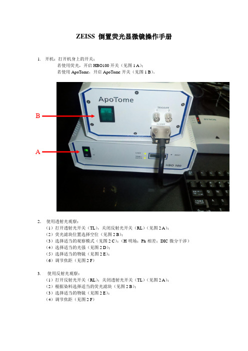
1.开机:打开机身上的开关;
若使用荧光,开启HBO100开关(见图1 A);
若使用ApoTome,开启ApoTome开关(见图1 B)。
B
A
2.使用透射光观察:
(1)打开透射光开关(TL),关闭反射光开关(RL)(见图2 A);
(2)荧光滤块位置选择空位(见图2 B);
(3)选择适当的观察模式(见图2 C);(H-明场;Ph-相差;DIC-微分干涉)(4)选择适当的光强(见图2 D);
(5)选择适当的物镜(见图2 E);
(6)调节焦距(见图2 F)
3. 使用反射光观察:
(1)打开反射光开关(RL);关闭透射光开关(TL)(见图2 A);
(2)根据染料选择适当的荧光滤块(见图2 B);
(3)选择适当的物镜(见图2 E);
(4)调节焦距(见图2 F)
4. 利用相机获取图像:
(1)手动调节显微镜光路至相机(见图3 A )
(2)利用Axio Vision 软件进行拍摄(具体应用参加Axio Vision 操作手册)
D A
B C
E F A
5. 显示屏各项参数意义:
(1)物镜信息 (见图4A ):包含放大倍数(如20X )、数值孔径(如0.3)、物镜属性(如
LD-长工作距离;A Pln-平场;Ph1-相差)
(2)总放大倍数(见图4B ):如200X
(3)透射光开关(见图4C ):如ON 或OFF
(4)反射光开关(见图4D ):如○或●
(5)荧光滤块位置(见图4E ):如05 AF 430
E D C B A。
荧光显微镜操作说明书

荧光显微镜操作说明书欢迎使用我司生产的荧光显微镜。
为了能够准确并顺利地操作该设备,我们为您提供了以下的操作说明书。
请仔细阅读并按照步骤进行操作,以确保获得最佳的观察效果。
1. 安装与准备1.1 确保在操作荧光显微镜之前,您已经将其安放在一个平稳的台面上。
确保设备的底部有足够的空间,并保持周围环境整洁,避免灰尘、湿气和其他杂物对设备的影响。
1.2 使用专用的电源线将荧光显微镜连接到稳定的电源插座上。
1.3 确保荧光灯泡已正确安装,轻轻旋紧螺丝,使用调节凸轮进行灯泡亮度的调节。
2. 样本准备2.1 在操作荧光显微镜之前,准备好待观察的样本。
样本可以是细胞、组织切片、荧光染料等。
确保样本已经标记或染色,以与荧光显微镜的工作原理相符。
2.2 使用移液管将样本滴到盖玻片上,并轻轻覆盖一个玻璃片或载玻片。
确保样本层均匀薄且没有气泡。
3. 荧光显微镜操作步骤3.1 打开荧光显微镜的电源开关,并将放大倍数调至最低。
3.2 调节聚焦旋钮,使样本清晰地呈现在目镜中。
3.3 通过调节荧光滤光片,选择适当的荧光波长进行观察。
3.4 使用荧光显微镜配套的光源控制器来调节荧光灯的亮度。
3.5 通过调节眼PIE镜,使左右目镜成像重叠,获得清晰的三维像。
4. 荧光显微镜的功能与特点4.1 荧光显微镜具备普通显微镜的观察功能,同时能够通过荧光染色技术研究生物样本。
4.2 荧光显微镜的激发光源与观测光路相分离,可以有效地抑制杂散光的干扰,提高观测质量。
4.3 荧光显微镜配备多种滤光片和滤镜,可选择不同波长的激发光源和观测光源进行观察与记录。
4.4 荧光显微镜配备数字相机接口,可方便地连接到计算机进行图像采集和分析。
5. 注意事项5.1 使用前请仔细熟悉该设备的使用说明,并遵循安全操作规范。
5.2 操作荧光显微镜时,请注意保持实验环境的整洁和无尘,确保样本不受外界污染。
5.3 荧光显微镜操作结束后,将其电源开关关闭,并确保设备处于干燥通风的环境中。
荧光显微镜说明书
IMPORTANT: This Guide describes how to set up the LS720 (Section I) and start using Lumaview 720/600-Series (Section II). It is important that you follow this Guide.For assistance, please call 760-298-2355 or email support@ .Etaluma, Inc.3129 Tiger Run Court, Suite 112Carlsbad, CA 92010Lumascope™ and Lumaview™ are trademarks of Etaluma, Inc.™2009-2017 Etaluma, Inc. All rights reserved.LS720 Microscope (Lumascope)-- Startup Guide --withLumaview 720/600-Series SoftwareTable of ContentsI.Hardware: Setup of LS720A.Items included with LS720B.Optional Accessories (purchased separately)C.Recommended Computer SpecificationsD.Placing the LS720E.Phase ContrastF.BrightfieldG.LED PowerH.Installing ObjectivesI.About Lumaview 720/600-SeriesJ.Downloading and Installing Lumaview 720/600-SeriesK.Connecting the LS720L.Live Cell Imaging with LS720 in an IncubatorII.Software: Getting Started with Lumaview 720/600-SeriesA.Starting Conditionsunching Lumaview 720/600-SeriesC.Instrument CalibrationD.Instrument SetupE.Finding a Live Image With Manual FocusF.Snapping ImagesG.Generating Composite ImagesH.Recording Live VideosI.Setting Up AutofocusJ.Writing and Using ProtocolsK.Generating a Z-MapL.Editing a Z-MapM.Tiling Across LocationsIII.AppendicesA.Lumaview LS720/LS600-Series File OrganizationB.Installing Lumaview 720/600-Series on a Computer with Different Lumaview Version InstalledC.Capturing and Compiling Live Video Using AviSynth and MeGUID.Troubleshooting (in progress)This document is available for download at .I. Hardware: Setup of LS720A. Items included with LS720• USB communication cable• External power supply/cord with country-specific plug• Hex wrench (3 mm) for removing/replacing shipping lock• Fluorescence shroud• Calibration 1536 well microplate• Calibration 4x objectiveB. Optional Accessories (purchased separately)• Phase Contrast Accessory LS720 (Olympus)• Holder for 35 mm Petri dishes, fits inside Holder for 60 mm Petri dishes• Holder for 60 mm Petri dishes & Terasaki plates, SBS outer dimensions• Holder for microscope slides & 50 mm Petri dishes, SBS outer dimensions• Holder for 4 microscope slides in parallel, SBS outer dimension carrier• Lumaquant, image analysis software• Microvolution, deconvolution software licenseC. Computer SpecificationsWindows 7, 8, 8.1, or 10; Core i5 or better Processor; solid state 1 TB minimum HD; 4 GBminimum RAM, single 4K monitor or two with 1080p HD resolutionD. Placing the LS7201. Remove the LS720 from the shipping box (save box and packing materials) andplace on a sturdy bench or counter in a standard room environment.WARNING: You must remove red shipping lock before plugging the LS720 intopower! If not removed, the LS720 will be damaged!2. Using the supplied 3 mm hex wrench, loosen the 2 set screws on the top of theinstalled shipping lock. Loosen the 2 set screws (smaller and more internal) onthe bottom of the lock.3. Unscrew the 2 larger 1-inch screws on the bottom of the shipping lock completely. Slide the shipping lock toward you to remove.4. Keep the 4 set screws screwed into the shipping lock and place in a secure place along with the two1-inch screws and 3 mm hex wrench.WARNING: If packing the LS720 for shipment, you must install the red shipping lock before placing into the shipping carton! If not installed, the LS720 can be damaged!5. If the LS720 will be used in an incubator or hood, it is recommended that the initial setup be carriedout in a room with ambient conditions before placement into the specialized environment. SeeShipping lock6.Plug the external power supply/cord into the left side port (when viewing from the front) and theplug into an AC outlet. Wait to connect the USB cable to the computer (see Section I. G. below).E.Phase Contrast1.If using the Phase Contrast Accessory LS720 (Phase Accessory), remove it from its shipping box (savebox and packing materials). Attach the Phase Accessory by inserting the pegs on the bottom of the Phase Accessory arm into the holes on the upper surface (right rear) of the LS720. Make sure the pegs are fully seated and tighten the large thumb screw at the back of the Phase Accessory arm.2.Connect the free end of the Phase Accessory communication cable to the round port on the LS720back panel (left side) labeled External Lamp Power Out. This allows the Phase Accessory to becontrolled by Lumaview 720/600-Series. Insert the included Slider into the appropriate slot in the phase condenser body.F.Brightfield1.For optimal brightfield, use of the Phase Accessory (Section I.E. above) with the included Slider in anopen position (no phase ring) is recommended. The Phase Accessory provides collimated light and is directly connected to the LS720, allowing it to be controlled by Lumaview 720/600-Series. It should also be used when imaging in a dark environment such as an incubator. To mount the Phase Accessory above the LS720, see Section I.E. above. Brightfield images will be in gray scale due to the monochromatic CMOS camera.2.If the Phase Contrast Accessory is not available, ambient light in a typically lit area can sometimes beused. The light should be as uniform as possible to prevent shadows or other dark or light areas.Overhead fluorescent lighting can cause uneven brightness including a striped pattern; if observed, move the LS720 or partially shade the light to reduce unevenness across the sample.G.Installing Objectives1.Unscrew the white deck knob at the front of the instrument (side with LS720 logo) and raise the topdeck (the top layer of the hinged 2-layer deck). Unscrew the black cap (or previously installedobjective) on top of the optics block and screw in the objective. Do not overtighten. Lower the top deck and tighten the deck knob.2.When installing or changing an objective, carry out the replacement quickly to minimize the chanceof dust falling onto the mirrored dichroic filter. If any dust is observed on the filter, carefully blow it off using a compressed air duster, making sure to hold the can UPRIGHT and bending the straw to aim the air directly toward the filter. DO NOT tilt the can or liquid can be emitted, which will require further cleaning. Other methods to remove dust may damage the dichroic filter and must NOT be used.H.About Lumaview 720/600-Series1.The LS720 is controlled by the Lumaview 720/600-Series software program. The latest Lumaviewversion is downloadable from Etaluma’s website and must be installed prior to connecting yourcomputer for the first time to the LS720 (due to the need for two Drivers that are installed on the computer at the same time).2.Lumaview 720/600-Series will run on Windows 7, 8, 8.1, and 10. Both desktop computers andlaptops can be used, but the best visualization correlates with monitor resolution (Note: the monitor does not affect image resolution unless you are using a low quality monitor that affects your ability to judge focus). The computer should have Windows .NET Framework 4.5.2 or higher installed; see https:///en-us/library/bb822049%28v=vs.110%29.aspx for more information. If your computer has an earlier .NET version, downloading Lumaview may automatically take you to the Microsoft .NET download page.I.Downloading and Installing Lumaview 720/600-Series1.To download Lumaview 720/600-Series, go to /products/downloads (under theResources tab). Click on Lumaview 720/600-Series - ZIP link to start the download and save the folder when prompted. Go to your downloads location and click to open the Lumaview720_600-SeriesInstall_v(version#).zip file.Alternatively, the same Lumaview 720_600-SeriesInstall_v(version#).zip file can be copied from the flash drive that comes with the LS720. Verify that this file is the latest version as posted on the Etaluma website.2.Lumaview 720/600-Series cannot run on a computer with Lumaview 500/400 installed. To uninstallLumaview 500/400, use the procedure described in Appendix B.3.To install Lumaview 720/600-Series, right click on the .zip file and Open with Windows Explorer.Double click on the .msi installer file to start the installation. You will be asked about the location;note that the default is a new Etaluma folder inside the Program Files (x86) folder. Duringinstallation, a Device Driver Installation Wizard will open. Click to continue (twice) and finishinstalling the two drivers. Installation of Lumaview 720/600-Series will then finish. Afterinstallation, a Lumaview 720/620-Series shortcut (orange circle) convenient for launching thesoftware will be present on the desktop.J.Connecting the Lumascope 7201.If connecting with a computer that has been off, turn computer on. Make sure computer isconnected to its monitor(s). Insert the standard USB-A end of the supplied USB communication cable into a USB port on your computer and the other square USB-B end into the square port on the LS720 left side. We highly recommend use of the same USB port on your computer each time you connect to the LS720. It is also best to connect the LS720 directly to the computer USB port rather than through a USB hub.If Lumaview 720/600-Series has not been run previously, it is important that the LS720 andcomputer be connected using the USB cable before launching Lumaview. This is because Windows needs to load the USB drivers before Lumaview can run. After the first time, the program can be launched before the LS720 and computer are connected. In the latter case, only the Outer Main Window will open (see Section II.B. below). Connecting the LS720 and computer with the USB cable will result in opening of the Live Image Window as well.K.Live Cell Imaging with LS720 in an Incubator1.Prior to imaging in an incubator, place the LS720 inside for 6-12 hr to allow equilibration to theincubator temperature.2.Place the sample on the LS720, focus, and close the incubator door. After 60 minutes, check thefocus. If satisfactory, imaging can be initiated.3.When live cell imaging at magnifications of 40x and above, the focus can sink several microns as themechanism relaxes. If the image has drifted out of focus, estimate the amount of focus knobrotation required to bring the image back into focus and overcompensate the same amount past the point of focus. Check the focus again after 60 minutes. The image should be in focus and imaging can be initiated. (Repeat process as needed).II.Software: Getting Started with Lumaview 720/600-SeriesThe following sections give instructions for getting started with Lumaview 720/600-Series on the LS720 and are intended as a quickstart guide only. Not all options are given and not all features may be explained in any particular section. The complete User Guide for Lumaview 720/600-Series is contained in the Help Section after Lumaview is opened. Click on Help in the Title Bar to open the pulldown menu and then click Contents, or simply Click F1 to open the Help Section. Becoming familiar with the complete Help Section is a must for using the LS720 optimally and taking advantage of the many features of this Microscope and accompanying software.CAUTION: When any LED is turned on, do NOT look directly at the light. Be sure to turn off all LEDs at the end of a session so any sample remaining on the deck is not photo-bleached.A.Starting Conditions1.Lumaview 720/600-Series has been downloaded and installed on the computer.2.The LS720 is connected to the computer via the UBS communication cable.3.The LS720 power cable is plugged into a standard AC outlet.unching Lumaview 720/600-Seriesunch the Lumaview 720/600-Series software from the desktop icon (or other chosen location) andallow the LS720 to be discovered. This may take a minute or so the first time. Two windows will open on your monitor:a.Live Image Window inside the larger Main Window. “Live Image Window” will be in the title barwhen the Window is not maximized. When Live Image Window is maximized, [Live ImageWindow] transfers to the end of the Main Window title bar.The Live Image Window status bar at the bottom shows communication with the sensor viacontinuous display of several useful metrics: current frame rate, data transfer rate, number of frames collected thus far in the session, frame size, and session date and time start.b.Main Window with Lumaview 720/600-Series v(version number) in the title bar. When the LiveImage Window is maximized, the title bar becomes Lumaview 720/600-Series v(version number) – [Live Image Window].The LS720 will automatically initialize every time LV720/600-Series is started by moving the microplate carrier to the Home position. The Home Position consists of the left front corner of the microplate carrier frame being positioned over the objective that is retracted to the lowest Z level. No image can be obtained at the Home position.C.Instrument CalibrationIf this is the first time the LS720 has been connected to the current computer, it is first necessary to do a Calibration. Once completed, calibration is not needed unless a different computer becomes connected or the XY position appears to be different from the expected position, e.g., center of microplate wells.1.To calibrate the LS720, install the provided Motic EFN 4x Objective. Place the provided1536 well microplate into the microplate nest.2.Click Utilities in the File Menu bar and in the drop-down menu click Calibrate menu,click Calibrate to open its dialog box. A communication dialog box will open asking if a4x objective has been installed. Click Yes and the dialog box will close.3.The Live Image Window will now show red crosshairs, and the microplate carrier willmove so well A1 is close to being over the objective.4.Click the Manual Image icon in the left tool bar (top icon) to open its dialog box.5.To use ambient light for calibration (recommended; see Section I.F.), check Brightfield in ManualImage to activate Gain and Exposure sliders. Start with Gain as low as possible and adjust Exposure until a mid-gray tone is shown in the Live Image Window.6.If using the Phase Contrast Accessory for brightfield illumination (Section I.F. above),move the phase slider to an open position (without phase ring) and turn the phasecondenser aperture (small lever on condenser front above Slider) so only a low level oflight is transmitted. In Manual Image, check Brightfield, set Gain and Illumination tothe lower levels, and lower Exposure as needed until a mid-gray tone is shown in theLive Image Window.7.In Calibration, move the Focus slider up while watching the Live Image Window todetect when the well outline can be seen and is sharp. The Focus slider area willbecome green whenever the Focus slider is active. Using the X/Y Move arrows (andStep size arrows if needed), move the microplate carrier until the A1 well is centered in the Live Image Window. Make sure the centered well is A1 by moving the image to the left and up using the X/Y Move arrows, and then re-center the A1 well.8.Continue to adjust the focus using the Focus Z up and down arrows until the well outline is in sharpfocus.9.In Calibration, click Accept Calibration. The Calibration dialog box will now convert tothe Manual XYZ dialog box.10. Test the calibration on other wells by clicking the Manual XYZicon in the left tool bar (second from top) to open its dialogbox (latter step needed if Manual XYZ was not previouslyopen). Click the Select Labware button to open its dialog box.Click on Generic1536WellMicroplate.elf to highlight it andthen click OK. The appropriate Labware Map dialog box (1536well in this case) will open. Click on any well and themicroplate carrier will move to center that well over theobjective. Test the microplate corners and other wells distantfrom each other. If any wells are not centered, repeat theCalibration procedure described above in this Section.D.Instrument Setup1.Click on Configuration in the File Menu bar to open the drop-down menuand select Instrument Setup to open its dialog box.2.Check the Lumaview version to make sure it is the most recently postedversion on the Etaluma website(/products/downloads/). Ensure LS720 is checked.3.Click the Objective button to open its dialog box (called Objective LensSelection). Select the desired objective to highlight it. Note that theother fields about the objective and image automatically fill based onmagnification and a frame size of 1600 x 1600 pixels. Click OK. Afterselection, the same information automatically fills in Instrument Setup.4.Click the Frame Size button to open its dialog box. Using the pull-down menu, select frame size (frame size will be the numbertimes itself because it is square). While the maximum is 1900 x1900 pixels, the default is set to 1200 x 1200 pixels. Note: 1700x 1700 pixels is the maximum recommended frame size butthere will still be some vignetting in the corners. (Whencapturing live video, if faster frame rates are needed, usesmaller frame sizes, e.g., < 1200 x 1200 pixels.)If a different Frame Size is chosen and OK is clicked in Frame Size, a communication dialog box will open directing you to shut down and restart Lumaview. Click OK and then shut down Lumaview.Upon restarting Lumaview, the frame size in the lower status bar will bethe new size. If a different frame size is selected and the computer is notrestarted, the new frame size may show in Instrument Setup but it may notactually be changed. Always check the lower left status bar of Live ImageWindow to make sure your desired changes have been incorporated.5.Continue to check the various settings in Instrument Setup. Root:Enter desired file name root for all images in a run or test. Select thefile format desired (Tiff is recommended).6.Select the time in seconds for each LED to be on before image snap. One second is typically used forfluorescence. Check Auto Composite to have images in multiple channels automatically composited and saved in the Composites folder. Check Individual Channel Folders to have images for each channel saved in a separate folder (e.g., for compiling a time-lapse video in one channel).7.Of the next 6 features listed on the left, check those desired:a.Date/time label will be displayed in the lower left corner of each image.b.Region within the field of view (FOV) used for autofocus will be displayed in the Live ImageWindow.c.Hot pixel removal. To set up this feature, click on Utilities and from the pull-down menu selectHot Pixel Mapping to open its dialog box. Information on next steps is available in the Helpsection.)d.Enable pseudo coloring results in live and snapped fluorescent images colored according to thechannel used and signal intensity.e.“Click” sound for manual image snap results in a “camera shutter-like” sound whenever amanual image is snapped.f.Manual snap auto-save results in images being savedautomatically without the Save As dialog box opening each time.Each image is numbered according to DOYHHMMSSmm whereDOY is day of year, HH is hour in 24 hour time, MM is minutes, SSis seconds, and mm is milliseconds. Each image number isunique and in numerical order.Not checking Manual image autosave will result in opening ofthe Save As dialog box every time after the camera icon is clickedand the image has been snapped. If the dialog box opens, enterthe desired file name and click Save.8.On the right side of Instrument Setup, checking Display scale bar results in scale bar in lower rightcorner of live and snapped images. Set Scale Bar Parameters, including color, whether to display the objective magnification, and width of the bar.9.Be sure to click OK to save the settings before exiting Instrument Setup.E.Finding a Live Image With Manual Focus1.Install the desired objective and sample labware. For labware thatis not SBS (microplate dimensions), use a labware holder such asthe Multi-Slide Holder for 1-4 microplate slides. Update Objectivein Instrument Setup as needed (Section II.D above) and click OK.2.Click on the Manual Image icon in the Left Toolbar (top icon) toopen its dialog box. Click the Manual XYZ icon in the Left Toolbar(second icon from top) to open its dialog box. Manual Image andManual XYZ will be used together to find and focus on samples inyour labware. If desired, move dialog boxes to the sides of theLive Image Window. If closed and then reopened, they will open in the same locationsprior to closing. Note: when Lumaview is closed, the dialog box positions will not besaved.3.Select a desired XY location in a sample labware using one of two options in Manual XYZ:e the X/Y Move arrows (and Step size arrows if needed) to move todifferent locations or wells in the sample labware, orb.Click on Select Labware to open its dialog box. Click on the labwaretype desired to highlight it and click OK. The appropriate Labware Mapwill then open. Click on a location and the microplate nest will move sothe location is centered over the objective. For further movementfrom the location, use the X/Y Move arrows (and Step size arrows ifneeded) in Manual XYZ. Clicking again on the original location inLabware Map will re-center on the location.4.In Manual Image, select the channel to use. For fluorescence, the includedShroud (or other protection from light) must be placed over the labware.Start with Exposure at maximum and Gain as low as possible. IncreaseIllumination gradually to the desired brightness. For dim samples, ifIllumination is at maximum, increasing the Gain can be used to increase signalbut it will also increase the background.For brightfield using ambient light, start with Gain as low as possible and adjust Exposure until a mid-gray tone is seen in the Live Image Window.For brightfield using the Phase Contrast Accessory (use open position in Slider, see Section I.F.), check Brightfield in Manual Image and turn the phase condenser iris (on front of condenser) so onlya low level of light is transmitted. Turn Exposure to near maximum and Gain to very low. IncreaseIllumination (%) until a mid-gray tone is seen in the Live Image Window.For phase contrast using the Phase Contrast Accessory (use appropriate Slider phase ring forobjective, Section I.E.), check Brightfield in Manual Image and turn the phase condenser iris (on front of condenser) to the left to the fully open position. Turn Exposure and Gain to very low.Increase Illumination (%) until a mid-gray tone is seen in the Live Image Window.5.In Manual XYZ, move the Focus slider up while watching the Live Image Window to detect thesample coming into focus. Continue to adjust the focus using the Focus Z up and down arrows (and Step size arrows if needed) until a sharp image is achieved. Adjust the Illumination and Gain settings during the focus process. Click the Set Bookmark button to record the focus level for easier return to this level.6.To facilitate the focusing process, click on the Zoom icon on the Left Tool Bar (seventh from the top).The Zoom feature toggles between displaying the entire image fitted to the Live Image Window and displaying the image matched 1:1 with the monitor resolution (pixel: pixel). If the monitorresolution in pixels is less than the frame size, the image will be enlarged (zoomed). The Live Image Window will now show a center portion of the entire image. Click the Zoom icon again to fit the image to the Live Image Window.F.Snapping Images1.When the desired field has been illuminated and focused in Live Image Window (Section II.E. above),click the Camera icon in the Left Tool Bar (third from the top) to snap the image. If the Zoomfunction was used to focus, the image captured will include the entire image, not just the portion visible on the monitor while in Zoom mode. If “Click” sound for manual image snap was checked in Instrument Setup, a click will sound when each image is snapped and a negative of the image will appear briefly on the Live Image Window.2.If Manual image auto-save was checked in Instrument Setup, images will be saved automaticallyusing the time-based numbering system (see Section II.D.7.f. about Instrument Setup for moreinformation). If Manual image auto-save was not checked, a Save As dialog box will open after the image was snapped (see Section II.D.7.f. about Instrument Setup for more information.) Images will be saved in the Etaluma folder formed automatically whenever Lumaview (any version) isdownloaded and installed. See Appendix B for the automatic subfolder directory that is formed automatically within the Etaluma folder.3.Images are captured and saved as seen by the camera, i.e., from the bottom. If desired, images canbe flipped horizontally to show how they would appear from the top. In the example Manual XYZ dialog box shown in this Guide, the “Horz flip image” is checked and “The image is flippedhorizontally and so appears as if viewed from above” is displayed at the top of the dialog box.4.To view the last image snapped, click the Folder icon in the Left Tool Bar (bottom icon) to launchWindows Explorer and open the most recently used Destination Folder.G.Generating Auto Composite Images1.Click the Composite icon in the Left Tool Bar (fourth from the top) to openits dialog box. Check the channels desired. To use values optimizedpreviously in Manual Image (Section II.E above), click Use Manual Settingsto upload the settings. Values can also be entered manually.2.Click OK to start the snapping of individual images in series. Each LED willturn on for the pre-snap interval and then flash when the image issnapped. If “Click” sound for manual image snap was checked in Instrument Setup, the click sound will be heard.3.The composite image will appear automatically in the Main Window matched 1:1 with the monitorresolution (pixel:pixel) and with its Title Bar showing the full path where it is located.H.Recording Live VideosEtaluma provides several options for compiling videos:1.Lumaquant software offered by Etaluma (see Lumaquant Startup Guide) for compiling imagesinto video),e of your own compiling software such as ImageJ, Fiji, MSMoviemaker, iMovie, ore of two freeware software programs together, i.e., AviSynth and MeGUI (instructionsdescribed in Appendix C).I.Setting Up Autofocuse Manual Image and Manual XYZ to find a focused live image in a desired XYposition as described in Section II.E. above. In Manual XYZ, click the AutofocusSetup button to open its dialog box.2.Transfer the manually determined Focus Z level in Manual XYZ to the Centerposition field of Autofocus Setup. The Focus range will be set to a default valuebased on the objective entered in Instrument Setup. The Max focus time will be setto the default of 15 sec.3.Click OK and autofocus will occur. The Focus Z level in Manual XYZ will now beupdated to the new autofocused Z level. Also in Manual XYZ will be the time takento reach autofocus, i.e., the Autofocus time (sec).4.If autofocus did not result in a sharp live image, make sure the Center positiontransferred was correct. In general, if autofocus consistently uses the full Maxfocus time, the range is too great for the time entered or the time is insufficient.It may be necessary to decrease the Focus range and/or increase the Max focustime. Higher magnifications (20x and greater) will require greater autofocus time。
Leica荧光显微镜操作指南

荧光显微镜型号:Leica DMR生产商:德国Leica公司Leica 荧光显微镜操作指南有关显微镜的的结构:荧光显微镜荧光汞灯:荧光汞灯价格昂贵,样品应集中观察,荧光光源关闭后距离下次开机时间须在30分钟以上,否则会大大降低你观察的效果及灯泡的寿命。
更换新的灯泡后第一次使用必须持续15-30分钟后方可关闭荧光电源。
光圈:孔径光阑挡板,荧光转换光路倾斜器:照明视场光阑:一般调至最大不动变倍器:1.0×,Bose 一般不用只有在相差时选用。
照相机拍照转换档:不拉出为不能拍照只能观察,拉出一半即能观察又可拍照,全部拉出只能拍照目镜观察不到。
双目镜筒:HC荧光滤光片1为普通光2为蓝光3为绿光4为紫外光物镜转盘:100倍为油镜,40倍与100倍之间应有空挡便于加油取片。
(注意:转换镜头时应转动物镜转盘齿轮,不应转动物镜,否则会导致物镜过紧或过松,易使物镜损坏。
)载物台:上有压片夹(注意:放取样本时应扳动压片夹小夹不应直接扳动压片夹)XY调节机械装置:将样品前后左右移动聚光镜转盘:10倍以上要用聚光镜相差环:H 明场直接观察亮1、2、3、相差,观察不染色的样品D 暗场主要用于观察金属材料显微镜臂上有焦距调节,粗的调节钮为粗调调节幅度较大,细的调节钮为细调,调节幅度小慢调节。
基座:A孔径光阑高大低小,相差时最大视场光阑一般最大Gray on 光强减少,off 光强增大DLF( Day Light Filter )一般白光滤片N4灰度滤片减少1/4Green:绿色滤片B 调中操作指南:1.使用显微镜前,请打开空调除湿一小时。
若不除湿观察样品所拍的照片中会留下水渍状斑。
2. 打开总电源,打开电脑,打开电脑桌面上的的Adobe Photoshop软件的下拉菜单Import Leica.3 打开显微镜上的电源。
注意只有进行荧光观察时才能打开荧光电源,否则不要打开,以免影响高压汞灯的寿命。
其它同普通显微镜的操作注意事项。
2.荧光显微镜的使用方法与注意事项

荧光显微镜的使用方法与注意事项1、打开显微镜电源。
2、需要使用荧光才开启荧光光源,开启汞灯需要记录打开和关闭的时间。
提示:两次开启汞灯的时间必须间隔半小时以上,打开汞灯后,必须半小时后方可关闭。
3、擦拭镜头:擦拭目镜和物镜。
在长纤维脱脂棉签顶端蘸上无水乙醇,从中央部分开始,采用螺旋渐进的方式轻轻逐步擦到边缘。
提示:①无需经常将物镜/目镜拆下来清理擦拭,日常使用时仅需用脱脂棉签及擦镜纸配合无水乙醇擦去油污即可,只有遇到顽固污渍时才应将物镜拆卸清理。
擦拭镜头时,动作应轻柔,不能过于用力,以避免损坏镀膜层。
②留意擦镜纸的两个面,纹路是不同的:其中一面是粗糙的,另一面更光滑些,要使用更光滑的那一面来清洁。
一般不建议用干的擦镜纸直接擦拭,同样可能划伤镜头。
4、放置样本,正置显微镜将样本放至物镜下方,倒置显微镜将样本放至物镜上方。
提示:显微镜样本一定要保持干净,如有盖片样本,一定要干净干燥,以免样本上的试剂污染物镜。
免疫荧光染色用抗荧光淬灭剂封片。
HE染色、免疫组织化学染色、高尔基染色等用中性树脂封片。
5、选择适合于自己实验的物镜放大倍数,由低到高进行观察。
6、选取实验相应方案,如光强,shutter,明场/DIC等。
切换滤光片,将荧光染色标本所需的激发滤光片组转入光路。
提示:选择与荧光染色标本相应滤色块。
如UV——DAPI,hochest等(镜下观察为蓝色);蓝光——FITC,Alex488等(镜下观察为绿色);绿光——Alex555,Cy3等(镜下观察为红色)。
7、实验结束,关闭电源。
提示:①显微镜使用过程中,镜体、灯箱及电源等位置应无遮挡或覆盖,以免影响散热从而损耗显微镜寿命。
显微镜使用完后,等灯箱部分冷却后,再盖上防尘罩。
②显微镜包含很多光学部件,避免显微镜碰撞,以保护光学系统。
显微镜属精密仪器,如需搬动,拆修,请联系专业人员。
荧光显微镜使用说明书

荧光显微镜使用说明书1. 引言荧光显微镜是一种高级显微镜,它通过荧光染料和荧光体来观察生物样本。
本说明书将向用户介绍荧光显微镜的基本操作和注意事项。
2. 设备使用前的准备在开始使用荧光显微镜之前,请确保以下准备工作已经完成:2.1 样本准备- 准备待观察的生物样本,并进行适当的固定和染色处理。
- 使用适当的荧光染料标记待观察的目标结构,比如细胞核或细胞器。
- 确保样本处于干燥且无尘的环境中,以免影响显微镜观察效果。
2.2 显微镜设置- 将荧光显微镜放置在水平且稳定的台面上,避免震动。
- 连接电源线并确保电源稳定。
- 打开显微镜主机,并调节照明系统到适当的亮度。
- 确保镜头已正确安装并调节到焦点位置。
3. 操作步骤3.1 调节荧光滤光片- 根据所使用的荧光染料种类,选择相应的滤光片组合。
请参考荧光染料厂家提供的荧光光谱信息。
- 将滤光片安装到显微镜的滤光器单元上,确保滤光片与光源相匹配。
3.2 焦距调整- 放置已准备好的样本到显微镜的载物台上,并使用载物台调节样本水平位置。
- 通过调节镜头的焦距轮和对焦杆,使样本逐渐变得清晰可见。
3.3 荧光成像- 使用显微镜的放大倍率调节旋钮,逐渐增加放大倍率以观察细节。
- 通过调节显微镜的聚光镜或荧光照明系统,确保样本受到均匀且适当的荧光照明。
- 使用取景器或相机从目镜观察孔观察并记录样本图像。
4. 注意事项- 在操作显微镜时,请务必小心轻放,避免撞击或其他损坏。
- 建议在室温下使用荧光显微镜,避免极端温度或湿度对设备造成不利影响。
- 使用前请确保手部清洁,避免在样本处理过程中引入杂质。
- 镜头润滑剂可能对荧光染料造成负面影响,请避免使用含润滑剂的显微镜油。
- 使用完毕后,请关闭显微镜并拔出电源线。
5. 故障排除如果在使用荧光显微镜过程中遇到问题,请尝试以下解决方案:5.1 样本无法观察到荧光信号- 检查荧光滤光片是否正确安装。
- 检查荧光染料是否已正确标记在待观察的结构上。
XDXD-RFL系列荧光显微镜使用说明书

(1)更换保险丝前,必须将显微镜主开关及汞灯电源 箱开关均置于“O” (OFF)状态,拔掉电源线。
(2)用手指扣住保险丝固定座②下方凹槽处①,从 保险插座⑤中拔出,从保险丝固定座②上方凹 槽处③取出保险丝组④,换上新的保险丝后, 在放进凹槽处③,将保险丝固定座②轻推入保 险插座⑤,听见“喀嚓”一声安装完成。(如图 13)
6
图8 图9 图 10 图 11
XD - RFL 荧光系列
2-2-3 安装汞灯灯源组
(1)用 M4 的内六角扳手将紧固螺钉①旋松。(如图 9) (2)将汞灯灯源组②轻轻推入荧光装置连接体③中,
并且推到底,然后旋转灯源组,使之上平面④处 于水平位置,再用 M4 的内六角扳手拧紧紧固螺 钉①。
★ 在使用过程中,应确保灯源周围有足够的空间散 热,特别是在灯源的顶面和底面。
★ XD-RFL 荧光显微镜只能同时安装两组荧光滤光 镜组进行观察,标准配制为 B1 和 G1 两个波段, 也可选购其它波段进行观察。
★ 按以上的方法将荧光滤光镜组 G1 安装到导轨座 左边位置。
★ 荧光滤光镜组安装时按两侧面的标记(如 DMB1) 方向正确安装 ,不能上下颠倒放置。
★ 在观察时,左、右防护罩不能被拆下,因为它们 在荧光滤光镜组移动时起到了一个保护的作用。
(2)避免将显微镜放置在有阳光直射、高温或高湿、 多尘、以及容易受到强烈震动的地方,确保工作 台平坦、水平并足够坚固。工作环境要求:室温 5℃~40℃,最大相对湿度 80%。
(3)需要移动显微镜时,双手分别紧握观察筒的较低 侧①和照明组件支架②。(如图 1)
(4)荧光显微镜使用时要在光线尽量暗的环境下进 行。
下面图解如何安装各种组件,数字表示安装顺序。 ★ 安装前,应确认各部分没有灰尘、污物以及其它影响组装的异物。 ★ 安装时要小心,注意不要刮、擦任何部分或碰到玻璃表面。
荧光显微镜使用方法说明书
荧光显微镜使用方法说明书一、概述荧光显微镜是一种用于观察和研究荧光材料的显微镜,其原理是通过荧光标记技术使样品发出特定波长的荧光,以增强对样品的观察和分析能力。
本使用说明书将详细介绍荧光显微镜的使用方法,帮助用户正确操作和维护仪器。
二、仪器配置与组装1. 基本配置荧光显微镜主体部分包括显微镜主体、荧光照明系统、像差校正系统等。
除此之外,还需要配备适当的滤光片、显微镜物镜、光源等附件。
2. 组装步骤a) 将荧光显微镜主体放置于平稳的工作台上,确保镜筒与显微镜架正常插入。
b) 连接荧光照明系统,确保光源与显微镜主体之间的连接牢固。
c) 安装所需滤光片和物镜,注意正确对准并轻轻旋固定。
三、荧光显微镜的使用方法1. 准备样品根据实验需求,准备好要观察的荧光标记样品。
样品应进行适当的处理和固定,以确保观察结果的准确性。
2. 调节光源与荧光照明a) 打开荧光照明系统,并调节合适的光源亮度和荧光照射时间。
b) 使用滤光片,选择合适的荧光激发波长,避免背景干扰。
3. 调节对焦与镜头切换a) 通过转动焦距调节手轮,将样品调至清晰可见。
b) 利用显微镜附件,如镜筒切换器、滤光片切换器等,按需切换并调整观察条件。
4. 图像采集与分析a) 连接相应采集设备,如相机、计算机等。
b) 在合适的荧光激发条件下,采集样品图像,并进行相关的分析和处理。
四、维护与保养1. 日常维护a) 避免直接日光照射,保持仪器干燥清洁。
b) 注意使用时避免碰撞以及接触腐蚀性物质。
c) 定期清理镜头、滤光片等附件,并保持其表面光洁度。
2. 镜头保养a) 使用专用镜头纸轻轻擦拭,避免使用过于湿润或有腐蚀性的物质。
b) 镜头不使用时,应盖上防尘罩,并存放在干燥通风的地方。
3. 故障排除在使用过程中,如发现显微镜工作异常或出现故障,请参照用户手册进行故障排除或联系售后服务人员。
充分了解荧光显微镜的使用方法,能够帮助您更好地进行荧光标记实验,提高实验效果和研究成果的可靠性。
- 1、下载文档前请自行甄别文档内容的完整性,平台不提供额外的编辑、内容补充、找答案等附加服务。
- 2、"仅部分预览"的文档,不可在线预览部分如存在完整性等问题,可反馈申请退款(可完整预览的文档不适用该条件!)。
- 3、如文档侵犯您的权益,请联系客服反馈,我们会尽快为您处理(人工客服工作时间:9:00-18:30)。
荧光显微镜使用指导书
一、荧光显微镜的整体布局说明
图中项目说明:
A--荧光显微镜光路部分
B--光路电源及数据采集卡
C--数据采集电脑
A1----汞光
A2----卤素灯
A3----卤素灯(底光)
A4----滤光模组
A5----目镜组
A6----观察模式切换(目镜/数据采集)
A7----反光镜
A8----差分光度计
1----卤素灯A2电源
2----汞光A1电源
3----数据采集卡
二、观察外延表面状态
1,打开卤素灯A2电源开关1并通过卤素灯A2电源开关1上的旋钮调整其亮度(如图1,具体亮度可根据个人要求决定)。
2,同时确定卤素灯A2与汞灯A1之间的反光镜扳手A7处于如图2所示位置以使卤素灯A2的光线进入主光路。
图1 卤素灯电源1图2 反光镜扳手位置
图3 滤光片插条位置图4 滤光模组A4
3,确定左边的D/UV插条进入光路,调整其余两个ND4和ND32插条以使进入光路的亮度合适(如图3),如需要微调可以通过改变右侧光栅插条(标注:A.STOP)的状态以达到合适的亮度,如需要调整视野的大小可以通过调整右侧的光圈插条(标注:F.STOP)来达到(一般情况下不需要调整)。
4,转动滤光模组A4的转盘选择4#滤光模组(如图4)。
5,在载物台上放上需要观察的样品,先选择目镜A5中低倍目镜去选取要观察的区域并且调整焦距使视野内的观察物体清晰,然后切换
到合适放大倍数的目镜进行观察。
注意:调焦时先用低倍后用高倍。
调焦时先顺时针旋转粗准焦螺旋(如图5)把载物台升到最高位置并观察不要让物镜碰到物体;然后眼睛靠近目镜观察视场同时逆时针旋转粗准焦螺旋让载物台下降,当观察到视场最亮时切换细准焦螺旋进行调整(如图6)。
图5 粗准焦螺旋的调整图6 细准焦螺旋的调整
6,如需要调整观测样品表面显示的颜色,则需要差分光度计A8中3个透镜插条同时插入,然后通过其中带旋钮的插条调整表面颜色以方便观察(如图7)。
图7 差分光度计插条插入状态图8 差分光度计插条退出状态
注意事项:确定目镜转换头A4前的遮光板打开(通过扳手扳动调节)。
确定左边的D/UV插条进入光路以阻挡紫外光伤害眼睛。
三、观察量子阱结构状态
1,按照观察外延表面状态的操作顺序把要观察的片子放号并调整好
焦距。
2,打开汞灯A1的电源开关2(如图9),然后按下IGNITION键以点亮汞灯(如图10)。
扳动反光镜扳手A7处于图11位置。
图9 图10 图11
3,把左边的D/UV插条退出光路,调整其余两个ND4和ND32插条以使进入光路的亮度合适。
退出差分光度计插条(如图8)。
4,根据要观察的外延结构选择不同的滤光模组(5#、6#、1#)对量子阱的结构进行观察。
注意:此状态下不要采用4#滤光模组进行观察,以防止强光刺伤眼睛。
观察结束要马上切断汞灯电源。
四、图象数据的采集
1,调整好焦距使要观测的物体在目镜内呈现的图形清晰,然后打开数据采集连接装置的开关(如图12),等待其绿色的指示灯不再闪烁时可以打开NIS ELEMENTS D 2.30 数据采集软件并点击绿色按钮(如图13),然后如图14拉出显微镜数据采集切换的插条即可对数据进行采集和处理。
注意:在切换后原来的焦距可能有微小的变化,要稍做调整即可。
图12 图13 图14
2,在操作界面上最左侧常用操作工具条(如图15),最右侧为其他操作工具条(如图16)。
在选择及添加了测量和定标图例后,如要保存这些标注,要选择“编辑”下拉菜单中的“嵌入叠加”才可把所有添加的图标与采集图象整合到一个图片上,然后保存。
图15 图16 图17
注意:定标及测量标注操作之前,要先如图17所示选择和物镜相应的放大倍数之后才能得到实际的测量数据。
五、关机
1,在测量结束后要及时关闭显微镜上各个光源的开关以延长其实际
使用寿命。
2,光路的设置要还原到初始状态。
具体各插条的状态参见图2/3/4/7。