电源滤波器技术规格书FSBP-10L
ME210-50A单相电源滤波器技术规格书
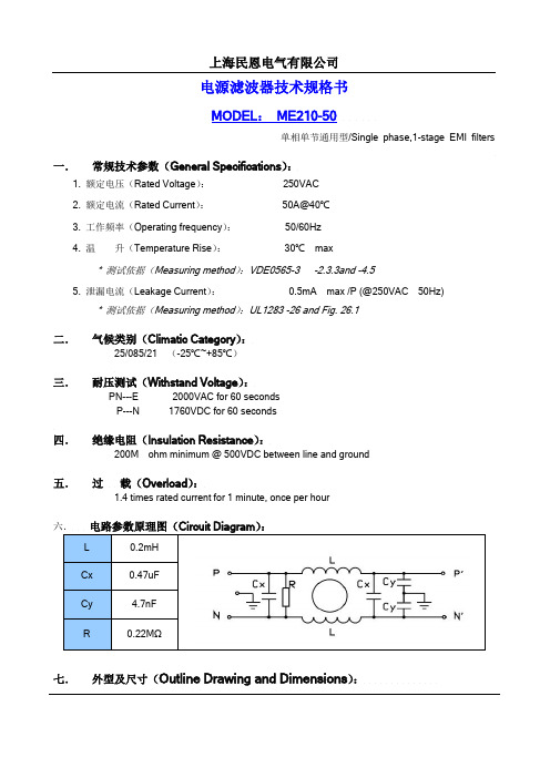
电源滤波器技术规格书MODEL:ME210-50单相单节通用型/Single phase,1-stage EMI filters一.常规技术参数(General Specifications):1. 额定电压(Rated Voltage):250VAC2. 额定电流(Rated Current):50A@40℃3. 工作频率(Operating frequency):50/60Hz4. 温升(Temperature Rise):30℃max* 测试依据(Measuring method):VDE0565-3 -2.3.3and -4.55. 泄漏电流(Leakage Current):0.5mA max /P (@250VAC 50Hz)* 测试依据(Measuring method):UL1283 -26 and Fig. 26.1二.气候类别(Climatic Category):25/085/21 (-25℃~+85℃)三.耐压测试(Withstand Voltage):PN---E 2000VAC for 60 secondsP---N 1760VDC for 60 seconds四.绝缘电阻(Insulation Resistance):200M ohm minimum @ 500VDC between line and ground五.过载(Overload):1.4 times rated current for 1 minute, once per hour六.电路参数原理图(Circuit Diagram):L 0.2mHCx 0.47uFCy 4.7nFR 0.22MΩ七.外型及尺寸(Outline Drawing and Dimensions):Unit: mm八.插入损耗(Insertion Loss):测试依据(Measured Method)Measured in 50Ω system, as IEC/CISPR NO.17插入损耗数据图表LINE TO GROUND(PN—E)共模(dB)LINE TO LINE(P---N)差模(dB)P/N .1 .15 .5 1 5 10 30 .1 .15 .5 1 5 10 30 ME210-50 6 9 18 24 50 62 45 20 21 52 70 66 60 60九.单只重量(Weight):550g(±20%)十.标识(Marking):1.生产厂商名称ME(民恩)2.产品名称电源滤波器3. 产品型号ME210-504. 工作电压及电流250VAC 50A5. 工作频率50/60Hz6. 工作温度-25℃~+85℃7. 输入输出端Line & load。
滤波器型号及技术参数1
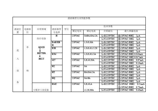
滤波器型号及性能参数滤波位置电源相位应用领域滤波器型号选择型号技术参数额定电压额定电流介质耐压最大泄漏电流进入设备单相医疗设备GOODBETTERBESTH 250V AC 3A6A10A15A L-G2250VDC @120V AC 60HZ 2µAL-N1450VDC@250V AC 50HZ 5µAEAH/EBH250V AC 1,3,6,10A L-G1500VDC @120V AC 60HZ 2µAL-N1450VDC@250V AC 50HZ 5µAEJH 250V AC 1,3,6,10,15,20 L-G1500VDC @120V AC 60HZ 2µAL-N1450VDC@250V AC 50HZ 5µAEJM 250V AC 1,3,6,10,15A L-G1500VDC @120V AC 60HZ 0.010mAL-N1450VDC@250V AC 50HZ 0.017mA MV 250V AC 3,6,10,20A L-G2250VDC @120V AC 60HZ 0.07mAL-N1450VDC@250V AC 50HZ 0.13mA HZ 250V AC 3A L-G2250VDC @120V AC 60HZ 2µAL-N1450VDC@250V AC 50HZ 5µAHT 250V AC 6A10A15A L-G2250VDC @120V AC 60HZ 2µAL-N1450VDC@250V AC 50HZ 5µAHQ 250V AC 3A/6A L-G2250VDC @120V AC 60HZ 2µAL-N1450VDC@250V AC 50HZ 5µA 大噪音工业设备EMC 250V AC 3,6,10,A15,20,30AL-G2250VDC @120V AC 60HZ 0.21mA@120V AC 60HZ 0.73mAL-N1450VDC@250V AC 50HZ 0.43mA进入设备单相@250V AC 50HZ 1.52mA FC 250V AC 6,12,16,25,36 L-G2250VDC @120V AC 60HZ 3.8mAL-N1450VDC@250V AC 50HZ 6.7mA S 250V AC 3,6,10,20 L-G2250VDC @120V AC 60HZ 0.4mAL-N1450VDC@250V AC 50HZ 0.7mA V/W 250V AC 3,6,10,20 L-G2250VDC @120V AC 60HZ 0.50mAL-N1450VDC@250V AC 50HZ 0.82mA T 250V AC 3,6,10,15,20 L-G2250VDCL-N1450VDC普通工业设备EDP/EOP 250V AC 1,3,6,10 L-G1500VDC @120V AC 60HZ 0.22mAL-N1450VDC@250V AC 50HZ 0.38mAB 250V AC 1,2,3,5,10,20,30 L-G2250VDCL-N1450VDCK 250V AC 1,2,3,5,10,20,30,40,60L-G2250VDC VK 0.5mA EK 0.21mAL-N1450VDC VK 1.0mA EK 0.36mA DK 250V AC 1,3,6,10,20 L-G2250VDC VDK0.4mA EDK0.22mAL-N1450VDC VDK0.7mA EDK0.38mA R 250V AC 1,2,3,5,10,20L-G2250VDC VR0.4mA ER0.21mAL-N1450VDC VR07mA ER0.36mA IEC320插座式SRB 250V AC L-G1500VDCL-N1450VDCEEA/EEB250V AC 1,3,6,10 L-G2250VDC @120V AC 60HZ 0.22mAL-N1450VDC@250V AC 50HZ 0.38mA EF 250V AC 1,3,6,10 L-G2250VDC @120V AC 60HZ 0.21mAL-N1450VDC@250V AC 50HZ 0.36mAEEJ 250V AC 1,3,6,10,15,20 L-G1500VDC @120V AC 60HZ 0.22mAL-N1450VDC@250V AC 50HZ 0.38mA EJS 250V AC 1,3,6,10,15,20 L-G1500VDC @120V AC 60HZ 0.22mAL-N1450VDC@250V AC 50HZ 0.38mA EBF 250V AC 1,3,6,10 L-G1500VDC @120V AC 60HZ 0.22mAL-N1450VDC@250V AC 50HZ 0.38mA ED 250V AC 1,3,6,10,15 L-G1500VDC @120V AC 60HZ 0.22mAL-N1450VDC@250V AC 50HZ 0.38mA EC 250V AC 1,3,6,10 L-G1500VDC @120V AC 60HZ 0.22mAL-N1450VDC@250V AC 50HZ 0.38mA EJT 250V AC 1,3,6,10,15,20 L-G1500VDC 1--15 200.22/0.38mA 0.20/0.40mAL-N1450VDC白色家用电器WG 250V AC 16A @120V AC 60HZA,B&C D,E&F0.74mA 0.10mA1.25mA 0.17mA三相FCD 相对相480V AC 6,16,25,36,50 L-G2250VDC相对线270V AC L-L1450VDCADT 480V AC 63,100,160,200L-G2210VDC @277V AC60HZ 1.3A@277V AC60HZ 2.6A@277V AC50HZ 4.6AL-L2158VDCAYO 相对相440V AC 3,6,10,20 L-G1500VDC相对线250V AC L-L1450VDCAYA 440V AC 16,25,36,50 L-G1500VDC @120V AC 60HZ 1.62mAL-L1450VDC@250V AC 50HZ 2.82mAAYC 480V AC 16,25,36,63,80,110,150,180 L-G 1850VDCL-L 1850VDCL-N 1450VDC@120V AC 60HZ 1.62mA@250V AC 50HZ 2.82mAA 440V AC 20,30,45,60 L-G 1500VDCN-G 1500VDCL-N 1450VDC @120V AC 60HZ 1.4mA @250V AC 50HZ 3.4mA滤波位置电源相位应用领域滤波器型号选择型号技术参数额定电压额定电流介质耐压最大泄漏电流从设备单医疗设备GOODBETTERBESTHEAH/EBHEJHEJMMVHZHTHQEN550XclassAX,Y,Z 250V AC 1,2,3,4,6 L-G2250VDC @120V AC 60HZ 0.30mAL-N1450VDC@250V AC 50HZ 0.50mA SK 250V AC 3,6,10,20,30,40L-G2250VDCL-N1450VDCEMC出来从设备出来相单相X辐射(CISPR)S 250V AC 3,6,10,20 L-G2250VDC @120V AC 60HZ 0.40mAL-N1450VDC@250V AC 50HZ 0.70mA V/W 250V AC 3,6,10,20 L-G2250VDC @120V AC 60HZ 0.50mAL-N1450VDC@250V AC 50HZ 0.82mA EP/VPG 250V AC 6,10 L-G2250VDCL-N1450VDCT 250V AC 3,6,10,15,20 L-G2250VDCL-N1450VDCclassBZU 250V AC 6.5A L-G2250VDC @120V AC 60HZ 0.30mAL-N1450VDC@250V AC 50HZ 0.50mA N 250V AC 6,10 L-G2250VDC @120V AC 60HZ 1.2mAL-N1450VDC@250V AC 50HZ 2.0mA Q 250V AC 3,6,20 L-G2250VDCL-N1450VDCFCIEC320插座式SRBEEJEJSEBFEDEC普通工业设备EDP/EOPBKDKREMC恶劣环境AQ 250V AC 3,6 L-G2250VDCL-L1450VDC三相FCD ADT AYO AYA AYC A。
斯奎特电源入口模块与电线滤波器FKHD说明书

1IEC Appliance Inlet C14 with Filter 2-Stage, Fuseholder 1-pole, Line Switch 2-poleSee below:Approvals and CompliancesC1470° CDescription- Panel mount :Screw-on mounting from front side - 4 Functions :Appliance Inlet Protection class I , Fuseholder for fuse-links 5 x 20 mm 1-pole , Line Switch 2-pole , Line-filter in standard version , 2 positions - Quick connect terminals 6.3 x 0.8 mmCharacteristics- Compact design with optimal shielding - All single elements are already wired- Plug removal necessary for fuse-link replacement - 2-stage line filter with increased attenuation With EMC-shield- Suitable for use in equipment according to IEC/UL 60950Suitable for use in medical equipment according to IEC/UL 60601-1Other versions on request- Medical version M80References Alternative: version with 1-stage filter FKHWeblinkspdf datasheet , html-datasheet , General Product Information , Distributor-Stock-Check , Accessories , Detailed request for productT echnical DataRatings IEC1 - 10 A @ Ta 40 °C / 250 VAC; 50 Hz Ratings UL/CSA 1 - 10 A @ Ta 40 °C / 125 VAC; 60 Hz Leakage Current standard < 0.5 mA (250 V / 60 Hz)Dielectric Strength> 1.7 kVDC between L-N > 2.7 kVDC between L/N-PE Test voltage (2 sec)Allowable Operation Tempe-rature-25 °C to 85 °CClimatic Category 25/085/21 acc. to IEC 60068-1IP-Protection from front side IP 40 acc. to IEC 60529Protection Class Suitable for appliances with protection class I acc. to IEC 61140TerminalQuick connect terminals 6.3 x 0.8 mm Panel Thickness S Screw: max 8 mmMounting screw torque max 0.5 Nm Material: HousingThermoplastic, black, UL 94V-0appliance inlet/-outletC14 acc. to IEC 60320-1,UL 498, CSA C22.2 no. 42 (for cold conditions) pin-temperature 70 °C, 10 A, Protection Class IFuseholder1-pole, Shocksafe category PC2 acc. to IEC 60127-6,for fuse-links 5 x 20 mm Rated Power Acceptance @ Ta 23 °C5 x 20: 1.6 W (1 pole)Power Acceptance @ Ta > 23°C Admissible power acceptance at higher ambient temperature see derating cur-vesLine Switch2-pole, non-illuminated, acc. to IEC 61058-1Technical DetailsLine FilterStandard Version, IEC 60939, UL 1283, CSA C22.2 no. 8 Technical DetailsMTBF> 1'200'000 h acc. to MIL-HB-217 FApprovals and CompliancesDetailed information on product approvals, code requirements, usage instructions and detailed test conditions can be looked up in Details about ApprovalsSCHURTER products are designed for use in industrial environments. They have approvals from independent testing bodies according to national and international standards. Products with specific characteristics and requirements such as required in the automotive sector according to IATF 16949, medical technology according to ISO 134485 or in the aerospace industry can be offered exclusively with customer-specific, individual agree-ments by SCHURTER.ApprovalsThe approval mark is used by the testing authorities to certify compliance with the safety requirements placed on electronic products. Approval Reference T ype: FKHDApproval Logo Certificates Certification Body DescriptionVDE Approvals VDE Certificate Number: 40004665UL Approvals UL UL File Number: E72928Product standardsProduct standards that are referencedOrganization Design StandardDescriptionDesigned according to IEC 60320-1Appliance couplers for household and similar general purposesDesigned according to IEC 60939Passive filters for suppressing electromagnetic interferenceDesigned according to IEC 60127-6Miniature fuses. Part 6. Fuse-holders for miniature fuse-linksDesigned according to IEC 61058-1Switches for appliances. Part 1. General requirements Designed according to UL 498Standard for Attachment Plugs and ReceptaclesDesigned according to UL 1283Electromagnetic interference filtersDesigned according to CSA C22.2 no. 42General Use Receptacles, Attachment Plugs, and Similar Wiring DevicesDesigned according to CSA C22.2 no. 8Electromagnetic interference (EMI) filters Application standardsApplication standards where the product can be usedOrganization Design StandardDescriptionDesigned for applications acc.IEC/UL 60950IEC 60950-1 includes the basic requirements for the safety of informationtechnology equipment.Designed for applications acc.IEC 60601-1Medical electrical equipment - Part 1: General requirements for basicsafety and essential performanceDesigned for applications acc.IEC 60335-1Safety of electrical appliances for household and similar purposes. Meetsthe requirements for appliances in unattended use. This includes the en-hanced requirements of glow wire tests acc. to IEC 60695-2-12 and -13. CompliancesThe product complies with following Guide LinesIdentification Details Initiator DescriptionCE declaration of conformity SCHURTER AG The CE marking declares that the product complies with the applicablerequirements laid down in the harmonisation of Community legislation onits affixing in accordance with EU Regulation 765/2008.RoHS SCHURTER AG EU Directive RoHS 2011/65/EUChina RoHS SCHURTER AG The law SJ / T 11363-2006 (China RoHS) has been in force since 1 March2007. It is similar to the EU directive RoHS.REACH SCHURTER AG On 1 June 2007, Regulation (EC) No 1907/2006 on the Registration,Evaluation, Authorization and Restriction of Chemicals 1 (abbreviated as"REACH") entered into force.White paper Glow wire test SCHURTER AG Meets the requirements of IEC 60335-1 for appliances in unattended use.This includes the enhanced requirements of glow wire tests acc. to IEC60695-2-12 and -13.Medical Equipment SCHURTER AG Suitable for use in medical equipment according to IEC/UL 60601-123Dimension [mm]Case 45Diagrams Standard versionNLPE’L’1)2)1) Line2) Load Medical version (M5)LPE’L’1)2)1) Line 2) LoadDerating Curves 1-poleA d m i s s i b l e p o w e r a c c e p t a n c e i n W a t tAmbient air temperature Ta °C4Attenuation Loss- - - - 50Ω differential mode _____ 50Ω common modeStandard version1 A2 A4 A6 A10 AMedical version (M5)1 A2 A4 A6 A10 AAll VariantsPackaging unit 10 Pcs AccessoriesDescriptionAssorted CoversRear Cover0859.0074Mating Outlets/ConnectorsCategory / DescriptionAppliance Outlet Overview completeIEC Appliance Outlet F, Screw-on Mounting, Front Side, Solder Terminal4787IEC Appliance Outlet F, Snap-in Mounting, Front Side, Solder or Quick-connect Terminal4788IEC Appliance Outlet F or H, Screw-on Mounting, Front Side, Solder, PCB or Quick-connect Terminal5091Appliance Outlet further types to FKHDConnector Overview complete4782 Mounting: Power Cord, 3 x 1 mm² / 3 x 18 AWG, Cable, Connector: IEC C1347824785 Mounting: Power Cord, 3 x 1 mm² / 3 x 18 AWG, Cable, Connector: IEC C1347854300-06 Mounting: Power Cord, 3 x 1 mm² / 3 x 18 AWG, Cable, Connector: IEC C134300-06IEC Connector C15 for hot conditions 120°C, Rewireable, Straight4781IEC Connector C15 for hot conditions 120°C, Rewireable, Angled4784Connector further types to FKHD...The specifications, descriptions and illustrations indicated in this document are based on currentinformation. All content is subject to modifications and amendments. Information furnished is believed18.12.2185。
电源电磁干扰(EMI)滤波器详细讲解
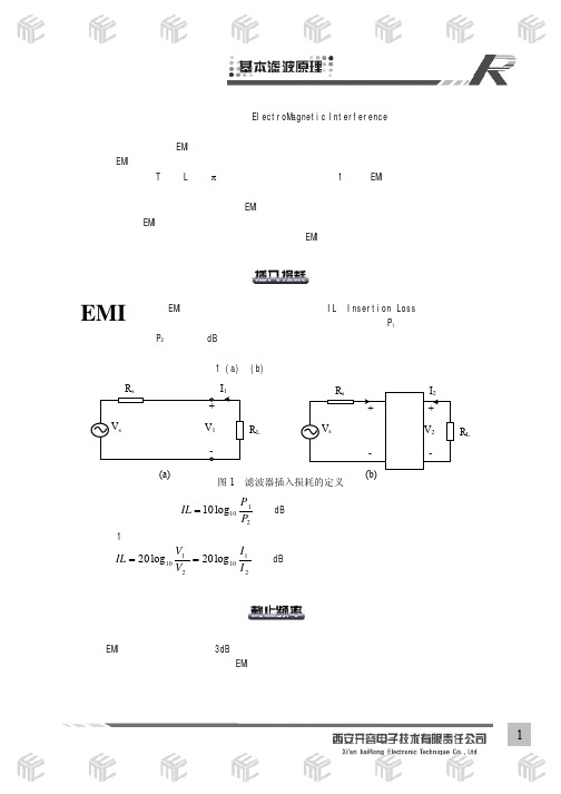
I1 I2
(dB)
定义 EMI 滤波器在频域内满足 3dB 插入损耗所对应的频点为截止频率。截止频率对于合理选用滤 波器非常关键,必须保证工作频率小于 EMI 滤波器的截止频率。
1
阻抗失配端接原则是应用 EMI 滤波器必须遵循的原则。根据网络理论,EMI 滤波器是双向无源网 络(标识其“源端”和“负载”端),在实际应用中,必须根据滤波器两端将要连接的源端阻抗和负 载阻抗,按表 1 来选择 EMI 滤波器的网络结构和参数,才能得到满意的 EMI 抑制效果。若不能满足阻 抗失配的原则,就会影响滤波器的插损性能,严重时甚至引起谐振,在某些频点处出现干扰放大现象。
测 试标准的确定为电源滤波器的各项指标提供了统一的衡定依据。其中最主要的测试项目包括插 入损耗测试、泄漏电流及耐高压测试等。
插入损耗测试方法参照 MIL-STD-220A 和 GB7343,这些标准都规定,共模和差模插入损耗是在 源端或负载端阻抗 50~75Ω间的某一阻值的系统内进行测量的(本公司产品插损数据采用 50Ω系统 进行测量),测试原理如图 9 所示:
在电子设备及电子产品中,电磁干扰(ElectroMagnetic Interference)能量可通过传导性耦合 或辐射性耦合来进行传输。为满足电磁兼容性要求,辐射性耦合采用屏蔽技术加以抑制,对传导性耦 合采用滤波技术,即采用 EMI 滤波器件加以抑制。
通用的 EMI 滤波器可以定义为一个低通网络,由电感、电容或电阻等无源元件组合而成。一般可 根据其电路形式分为 T 型、L 型、π型等基本电路形式(参见表 1)。但 EMI 滤波器不同于通常的信号 处理滤波器,二者所关心的滤波器指标、使用环境等都是截然不同的。普通的低通滤波器关心幅频特 性、相位特性、群延时、波形畸变等;而 EMI 滤波器更关心插入损耗、能量衰减、截止频率等参量。 从使用环境来看,EMI 滤波器在使用中必须考虑源端及负载端的端接阻抗对滤波性能的影响,而且在 使用中必须结合接地技术与屏蔽措施,才能达到良好的 EMI 抑制效果。
滤波器主要参数与特性指标-滤波器的主要性能参数
资料范本本资料为word版本,可以直接编辑和打印,感谢您的下载滤波器主要参数与特性指标-滤波器的主要性能参数地点:__________________时间:__________________说明:本资料适用于约定双方经过谈判,协商而共同承认,共同遵守的责任与义务,仅供参考,文档可直接下载或修改,不需要的部分可直接删除,使用时请详细阅读内容滤波器的主要参数(Definitions):中心频率(Center Frequency):滤波器通带的频率f0,一般取f0=(f1+f2)/2,f1、f2为带通或带阻滤波器左、右相对下降1dB或3dB边频点。
窄带滤波器常以插损最小点为中心频率计算通带带宽。
截止频率(Cutoff Frequency):指低通滤波器的通带右边频点及高通滤波器的通带左边频点。
通常以1dB或3dB相对损耗点来标准定义。
相对损耗的参考基准为:低通以DC处插损为基准,高通则以未出现寄生阻带的足够高通带频率处插损为基准。
通带带宽(BWxdB):指需要通过的频谱宽度,BWxdB=(f2-f1)。
f1、f2为以中心频率f0处插入损耗为基准,下降X(dB)处对应的左、右边频点。
通常用X=3、1、0.5 即BW3dB、BW1dB、BW0.5dB 表征滤波器通带带宽参数。
分数带宽(fractional bandwidth)=BW3dB/f0×100[%],也常用来表征滤波器通带带宽。
插入损耗(Insertion Loss):由于滤波器的引入对电路中原有信号带来的衰耗,以中心或截止频率处损耗表征,如要求全带内插损需强调。
纹波(Ripple):指1dB或3dB带宽(截止频率)范围内,插损随频率在损耗均值曲线基础上波动的峰-峰值。
带内波动(Passband Riplpe):通带内插入损耗随频率的变化量。
1dB带宽内的带内波动是1dB。
带内驻波比(VSWR):衡量滤波器通带内信号是否良好匹配传输的一项重要指标。
滤波器型号
交流三相三线电源滤波器
双节增强型
ME460系列
三节高性能型
ME760系列
单节通用型
ME280系列
交流三相四线电源滤波器
双节增强型
ME480系列
三节高性能型
ME780系列
交流高电压电源滤波器
单相双节增强型 三相三线双节增强型
ME420H系列 ME460H系列
带插座通用型
ME160系列
IEC插座电源滤波器
具体情况调整输入、输出端,使滤波器两端阻抗都处于失配状态,以达到最佳的滤波效果。(具体技术 问题请咨询我司)。
电源滤波器系列选型
通过图①所示,为减小接地阻抗,滤波 器应安装在导电金属表面或通过编织接地带 与接地点就近相连,避免细长接地导线造成 较大的接地阻抗。
2
固定 安装至支架或机箱内,并拧紧螺母固定。
接地
将 接 地 螺 钉 以 截 面 积 6mm² 以 上、长度小于 5 米的软线与大地连接。
3 相线连接
取下滤波器相线螺栓上的螺母垫片 各 1 只,将接好线的端子依次安装在相线 螺栓上。注意各端子连线应尽量保证平 行。避免交叉!
电源滤波器放入低温箱(-25℃)和高温箱(+85℃)后,加上额定电压和额定负载,持续工作700小 时后,进行耐压测试、绝缘电阻测试、漏电流测试、插入损耗测试应满足企标。 3.电性能(L/C/R)测试、插入损耗测试、耐压测试、漏电流测试、绝缘电阻测试,采用相关仪器依据标准
操作规程进行。
电源滤波器系列选型
相线连接 钳住螺栓与螺母,用力拧紧。
(建议使用铜螺栓及螺母垫片进行连接。)
4 紧固螺栓
在通电之前检查滤波器各个位 置的连接及安装情况,特别注意接地 线的连接,检查无误后即可加电运 行。
FMP-10 和 FMS-10 产品说明书
FMP-10&FMS-10MPO TesterManualPlease read this guide before useSpecificationFMP-10&FMS-10FMS-10MPO Light SourceOptical Interface12cores MPO port(female)Wavelength850nmSpectral type VCSELChannel12Data Interface USBWavelength Recognition ReservedModulation CW(Low/High Power mode)、270Hz、1kHz、2kHz FMP-10MPO Power MeterSensor InGaAsOptical Interface12cores MPO port(female)Calibrated Wavelength850nm,1300nm,1310nm,1550nmChannel12Test Range-60dBm~+3dBmResolution±0.01dBUncertainty±0.5dBMaximum input power+13dBmUnit dBm/dB(REF)Threshold Setting4wavelengthReference Setting4wavelengthData storage300setsData interface USBWavelength Recognition YesPolarity Test According to TIA-568-C.0Frequence Recognition270Hz、1kHz、2kHzGeneralDisplay TFT-LCDAuto Power-Off YesPower Supply NiMH batteries/AC adapterWorking Hours≥10hoursWorking Temp0℃~50℃Humidity0~95%(non condensing)Dimension190L×105W×55H mmWeight About700gSafety InstructionsWarningTo avoid the risk of injury or death,always observe the followingprecautions before initializing the unit:To prevent hazardous radiation exposure,use only the controls oradjustments and perform only procedures specified for the lasersource.If using a voltage-reducing autotransformer to power theunit,ensure that the common terminal connects to the earthed poleof the power sourceUse only the type of power cord supplied with the unit.Willfully interrupting the protective earth connection is prohibited.Never look into the end of an optical cable connected to an opticaloutput device that is ser radiation is invisible,and directexposure can severely injure the human eye..for moreinformation,see the user’s manual of the laser source in use.Do not use the unit outdoors.To prevent potential fire or shock hazard,do not expose the unit toany source of excessive moisture.Do not operate the unit outdoorsDo not interrupt the protective earth grounding.Any such action can lead to a potential shock hazard that can result in serious personalinjuryTo prevent potential fire or shock hazard,do not expose the unit toany source of excessive moisture.Unless absolutely necessary,do not attempt to adjust or performany maintenance or repair procedure when the unit is open ed andconnected to a power source.Repairs are to be carried out only by a qualified technician.Do not attempt any adjustment,maintenance,or repair procedure to the unit’s internal mechanism if immediate first aid is not accessible Disconnect the power cord from the unit before adding or removingany components.Operationg the unit in the presence of flammable gases or fumes isextremely hazardousDo not perform any operating or maintenance procedure that is not described in the user’s manualStandard ConfigurationFMP-10&FMS-10tester、power adapter、Standard MPO jumper。
电源滤波器

EMI 电源滤波器
电源滤波器是低通滤波器的一种,是由电容、电感等无源元件构成的双向网络,利用阻抗失配原理抑制电源线上的干扰。
其滤波范围通常在0.015-50MHz之间,对此频带范围内的干扰信号提供最高可达100dB 以上衰减。
电源滤波器主要技术参数说明
1.插入损耗
插入损耗是衡量滤波器滤波效果的指标,通常以分贝数或频率特性曲线来表示。
它是指滤波器接入线路前后,电源传给负载的功率比或端口电压比。
IL=10lg Po/P2(dB) 或IL=20lg V o/V2(dB)
Po、P2、V o、V2分别表示滤波器接入前后负载端的功率和电压。
实验室测量一般在50/50Ω系统下进行。
2.最大泄漏电流
泄漏电流是指滤波器相线、中线对地(外壳)在250V AC、50Hz下流过的最大电流。
为保证安全,对不同类型、不同应用场合的滤波器,此项指标有不同规定。
3.绝缘电阻
绝缘电阻是指滤波器相线、中线对地之间的阻值。
通常用绝缘电阻表测试。
4.试验电压
试验电压指滤波器线至线、线至地间的抗电电压。
试验时间为1分钟。
滤波器不出现打火、击穿、损坏及性能下降等现象。
- 1、下载文档前请自行甄别文档内容的完整性,平台不提供额外的编辑、内容补充、找答案等附加服务。
- 2、"仅部分预览"的文档,不可在线预览部分如存在完整性等问题,可反馈申请退款(可完整预览的文档不适用该条件!)。
- 3、如文档侵犯您的权益,请联系客服反馈,我们会尽快为您处理(人工客服工作时间:9:00-18:30)。
北京天工通宇科技有限公司
拟制
2013.08.07
校对文件编号T
审核电源滤波器技术规格书
1 产品名称:电源滤波器2产品型号:FSBP-10L
3产品特点:含共模干扰、差模干扰滤波电路,常规通用,结构紧凑,面板固定安装,端接方式:焊片。
北京天工通宇科技有限公司
拟制
2013.08.07
校对文件编号T
审核电源滤波器技术规格书
5电路原理图:
LINE
LOAD 6 7 7.1 7.2 7.3滤波器输入端和输出端的布线:滤波器的输入线、输出线必须拉开距离,切忌并行走线,以避免输入线缆和输出线缆间发生耦合而旁路了滤波器,造成滤波器失效。