HoneywellS系列气体传感器应用电路pdf
Honeywell BW Solo - 无线气体检测器说明文档说明书
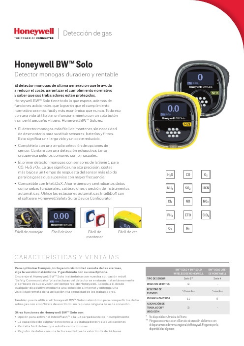
Detección de gasNOETOSO2H2NH3Cl2PH3HCNNO2C l O2H2S O2O3COFácil de manejar Fácil de leer Fácil demantenerFácil de verC A R AC T E RÍS T I C A S Y V E N TA J A SPara optimizar tiempos, incluyendo visibilidad remota de las alarmas,elija la versión inalámbrica. Y gestiónelo con su smartphone.Empareje el Honeywell BW™ Solo inalámbrico con nuestra aplicación móvil"Safety Communicator" y las lecturas del detector se enviarán instantáneamenteal software de supervisión en tiempo real de Honeywell. Acceda a él desdecualquier dispositivo mediante una conexión a Internet y obtenga unavisibilidad remota de la ubicación y la seguridad de los trabajadores.También puede utilizar el Honeywell BW™ Solo inalámbrico para compartir los datossobre gas con el software de escritorio; no requiere ninguna base de conexión.Otras funciones de Honeywell BW™ Solo son:• Opción para activar el IntelliFlash™ o la luz parpadeante de incumplimiento• La capacidad de asignar detectores a los trabajadores y a las ubicaciones• Pantalla fácil de leer que admite varios idiomas• Registro de datos con una lectura evolutiva de valor límite de 24 horasEl detector monogas de última generación que le ayudaa reducir el coste, garantizar el cumplimiento normativoy saber que sus trabajadores están protegidos.Honeywell BW™ Solo tiene todo lo que espera, además defunciones adicionales que lograrán que el cumplimientonormativo sea más fácil y más económico que nunca. Todo esocon una vida útil fiable, un funcionamiento con un solo botóny un perfil pequeño y ligero. Honeywell BW™ Solo es:• El detector monogas más fácil de mantener, sin necesidadde desmontarlo para sustituir sensores, baterías y filtros.Esto significa una larga vida y un coste reducido.• Complételo con una amplia selección de opciones desensor. Contará con una detección exhaustiva, tantosi supervisa peligros comunes como inusuales.CO, H2S y O2. Lo que significa una alta precisión, costesmás bajos y un tiempo de respuesta del sensor más rápidopara los gases que supervise con mayor frecuencia.• Compatible con IntelliDoX. Ahorre tiempo y centralice los datoscon pruebas funcionales, calibraciones y gestión de instrumentosautomáticas. Utilice las estaciones automáticas IntelliDoX conel software Honeywell Safety Suite Device Configurator.Honeywell BW™ SoloDetector monogas duradero y rentableBW™ SOLO Y BW™ SOLOWIRELESS DE HONEYWELLBW™ SOLO LITE*DE HONEYWELLTIPO DE SENSOR Serie 1**Serie 4REGISTRO DE DATOS Sí–REGISTRO DEEVENTOS50 eventos 5 eventosIDIOMAS ADMITIDOS115ASIGNACIÓN DETRABAJADOR YUBICACIÓNSí–* No disponible en América del Norte.** Póngase en contacto con el Servicio de atención al cliente o conel departamento de ventas regional de Honeywell Pregunte por ladisponibilidad al gestor.Honeywell BW™ SoloEspecificaciones técnicasDEBIDO A LA INVESTIGACIÓN CONTINUA Y A LAS MEJORAS CONSTANTES QUE SE APLICAN A LOS PRODUCTOS, LAS ESPECIFICACIONES ESTÁN SUJETAS A CAMBIOS SIN PREVIO AVISO.Datasheet_Honeywell BW Solo_DS110218-01_ES-ES | 11/18© 2018 Honeywell International Inc.* Solamente el Honeywell BW™ Solo Lite (no disponible en América del Norte).SISTEMA DE ACOPLAMIENTO INTELLIDOX IntelliDoX combina los módulos de acoplamiento inteligentes con nuestro sistema de gestión deinstrumentos para proporcionar pruebas automatizadasy facilitar la conservación de registros.Gestión de dispositivos con Honeywell Safety Suite/Safety SuitePara más información Honeywell HPPECra. 11a #98-50, Bogotá, ColombiaTamaulipas 141, 1° Piso, CDMX, México 06140Soporte al Cliente:e-mail:****************************。
Honeywell_传感器_技术参数 2
目录:水系统传感器 (2)水流开关WFS-1001-H (2)液位开关MAC-3-5M (2)水管式压差传感器P7620C (3)水管式压力传感器P7620A (4)流量变送器8550+2517 (5)VF20T浸入式温度传感器 (5)风系统传感器 (7)DPS系列气流压差开关 (7)DPTM系列压差变送器 (7)风管式温度传感器LF20 (8)风管式温度传感器LF20-C (9)室外温度传感器T7416A1022 (9)室内温度传感器T7412A1000 (9)室内温度传感器CTR21 (10)风管式温湿度传感器H7050B1018 (10)风管式温湿度变送器H7050B1117 (11)室内温湿度变送器H7030A1000 (12)室内温湿度传感变送器H7012B1023 (12)室内温湿度传感器CTR21-H (13)风管式温湿度传感器H7015B1020 (14)室外温湿度传感变送器H7508A1042 (14)CDS2000 系列二氧化碳传感器 (15)C7110C1001(替换已停产的AQS51) 系列二氧化碳传感器 (15)AQS71-KAM(替换已停产的AQS51-KAM) 系列二氧化碳传感器 (16)GD250W3E 系列一氧化碳传感器 (17)C7110A1005系列房间空气质量传感器 (17)L4064K1006B 高温断路开关,手动复位 (18)T6950A1000 低温短路开关,手动复位 (18)数字化挂墙模块T7560 温度传感器 (19)数字化挂墙模块T7460 温度传感器 (19)水系统传感器水流开关 WFS-1001-H应用∙ WFS 水流开关具有SPDT 输出,性能优异,高精度可靠性,可安装在水管和对铜无腐蚀性液体中,当液体流量达到整定速率时,可不到整定点,其一个回路关闭,另一个回路打开,典型应用于连锁作用或断流保护的场所。
∙ WFS 系列开关仅用0℃以上液体介质,它亦可于高盐或氯气的液体,但是非易燃介质。
西维克斯 2, 3, 4 复合气体探测仪 操作手册说明书
有限保证和责任限制BW Technologies LP (BW) 保证本产品自交付客户之日起在正常使用和保养情况下两年内不会出现材料和工艺方面的缺陷。
本保证仅适用于原客户购买的、未使用过的新产品。
BW 的保证责任为有限责任,对于在保证期内返回 BW 授权服务中心的缺陷产品,BW 有权自行选择是全额退款、维修还是更换。
在任何情况下,BW 依据本保证承担的责任均不超过客户购买产品时实际支付的价款。
以下情况不属于本担保范围:a)保险丝、一次性电池或使用过程中因产品正常磨损和破损而需要定期更换的零件;b)根据 BW 鉴定,任何因误用、改装、疏忽、意外事故或操作、处理、使用条件异常而损坏的产品;c)任何因非授权经销商维修或在产品上安装了未经许可的零件而造成的损坏或缺陷。
本担保所列出的责任受以下条件限制:a)保管、安装、校准、使用、维护并遵守产品手册说明和 BW 科技有限公司的其他任何应用建议议;b)客户及时就任何产品缺陷通知 BW ,必要时应迅速对产品进行修复。
除非客户收到 BW 的发货指示,否则不能返回任何产品;c)BW 有权要求客户提供购买凭证,如原始发票、销售契约或包装收据,以确定产品是否在保证期内。
客户同意本保证是客户可以获得的唯一补偿,并取代所有其他保证(无论是明示的还是暗含的),包括但不限于对于特殊目的适销性或适合性的任何暗含保证。
不论是由于违背了本保证还是依据合同、侵权行为或信赖或任何其他理论,BW 对特殊、间接、由于某些国家/地区或州/省不允许限制暗含保证的条款,或不允许排除或限制偶然或附带产生的损坏,因此本保证的限制和排除情况可能并不适用于每位客户。
如果本保证的任何规定被有资格的司法管辖法院认为无效或不可执行,将不会影响任何其他规定的有效性或可执行性。
BW Technologies by Honeywell 联系方式电子邮件地址: ********************BW Technologies by Honeywell 网址: 美国: 1-888-749-8878加拿大: 1-800-663-4164欧洲: +44(0) 1295 700300其他国家/地区: +1-403-248-9226珠海司福斯特科技有限w w w .s a f e d t e c h .c o m1GasAlertMax XT II简介本操作员手册提供操作 GasAlertMax XT II 气体检测仪的基本信息。
美国Honeywell霍尔传感器
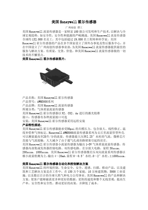
美国Honeywell霍尔传感器广州南创谭工美国Honeywell流量传感器是一家财富100强公司发明和生产技术,以解决与全球宏观趋势,如安全性,安全性和能源的严峻挑战。
美国Honeywell流量传感器全球约132,000名员工,其中包括超过19,000名工程师和科学家,美国Honeywell霍尔传感器的产品在多个国家设立了国外办事处及售后服务中心,并在中国设立了广州南创传感器事业部,为美国Honeywell流量传感器提供最佳的服务与解决方案。
有质量,交货,价值,和美国Honeywell流量传感器做的一切技术的不懈重点。
美国Honeywell霍尔传感器图片:产品名称:美国Honeywell霍尔传感器产品型号:AWM3000系列产品品牌:美国Honeywell流量传感器所属分类:气体质量流量传感器美国Honeywell霍尔传感器以N2、CO2、Ar进行的激光校准接口:传感器有各种流量接口可选安装:美国Honeywell霍尔传感器采用远程安装产品特性描述:美国Honeywell霍尔传感器能承受50psi的共模压力,包含放大、线性修正、温度补偿和气体标定,Honeywell AWM5000流量传感器系列为文丘里流量管型外壳,可以测量最高至20升/分的流量,传感器最大压降2.25″水柱的气流,微桥芯片直接与气流接触,大大减少了由于通气孔或旁路堵塞引起的误差。
美国Honeywell霍尔传感器小流量传感器为输出1-5V气体质量流量传感器,传感器内部集成发热器控制电路、双传感电路、差分放大电路,量程30sccm、200sccm、1000sccm。
美国Honeywell霍尔传感器微差压双向流量系列传感器以极小流量检测为主,输出4~20mA,量程0~0.5″水柱、0~2″水柱、±1000sccm。
美国Honeywell霍尔传感器自动化和控制解决方案美国Honeywell的环境控制,生命安全,安全,遥感,扫描,移动产品,以及建筑和工艺解决方案是在工作中,在150万个家庭,10万座建筑物,5000工业设施,以及数以百计的全球天然气和电力公用事业。
HONEYWELL流量传感器AWM系列-文档

HONEYWELL流量传感器AWM系列-文档本公司业代理美国honeywell霍尼韦尔空气质量流量传感器空气质量流量传感器有一个由加热器与温度敏感元件组成的薄膜,隔热的电桥式结构。
该电桥式结构对流过芯片的空气或其他气体流量有灵敏和快速的反应。
电源电压:8Vdc至15Vdc工作温度:-25摄氏度至85摄氏度(-13F-185F)介质相容性:仅限于干燥气体AWM2000系列微桥型空气质量流量传感器是一个无源器件,由2个惠斯通电桥组成,并具有双向传感的能力,按照技术要求,工作时需要一个加热器控制电路,和一个传感电桥馈电电路。
传感器中没有这两个电路,需用户自己设计。
差动放大器是传感电桥一个有用的接口。
它可用来对传感器输出引入增益和电压补偿。
信号调节:非放大型(输出-44,5mVdc至44,5mVdc)压力孔型式:直通型传感器电阻:5K欧流量/压力范围参考型号+_200 sccm AWM2100V+-4.0英寸水柱(10 mBar) AWM2200V+-1000 sccm(1 SLPM)(每分钟1标准升) AWM2300VAWM3000系列如同2000系列,是由双惠斯顿电桥控制空气流量的测量,该AWM3000系列为放大型,所以,它可用来对传感器输出提高增益和引入电压补偿。
加热器控制电路和传感电桥馈电电路都集成在传感器中。
信号调节:放大型(输出1 Vdc至5 Vdc)压力孔型式:直通型流量/压力范围参考型号+_200 sccm AWM3100V+_2.0英寸水柱(5 mBar) AWM3200V+_0.5英寸水柱AWM3201CR+_1000 sccm(1 SLPM) AWM3300V+_1000 sccm(1 SLPM)双向AWM3303VAWM40000系列微桥型空气质量流量传感器根据传热原理工作。
空气质量流量横穿过传感器元件的表面。
输出电压根据通过传感器进出口的空气质量流量或其他气体质量流量成比例地变化。
霍尼伟尔气体侦测器中文说明书
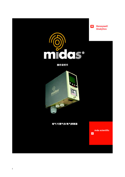
HoneywellAnalytics©2004 Honeywell Analytics Issue 1 12/2004 MIDAS-A-001目录1 目录 22 概述 53 产品概述 5 3.1 主机架 6 3.1.1 显示器模块 63.1.2 泵模块 7 3.1.3 传感器暗盒腔 73.2 安装托架底座 73.2.1 安装托架 73.2.2 终端模块 73.3 传感器盒 83.3.1 偏致传感器盒 83.4 机壳 84 默认配置 95 安装95.1 探测器的安装和定位 105.2 机械安装 115.3 样品和排气管道计算 125.4 在线过滤器 135.5 本地化探测器选购件 145.6 电气安装 155.7 电连接 17 5.8 改装主机架 185.9 安装传感器盒 196 探测器启动程序 197 总体操作 21 7.1 正常操作模式 217.1.1 重置报警、故障和维护故障 227.2 浏览模式 227.2.1 浏览模式菜单概述 237.3 设置、校准和测试模式概述 247.3.1 设置菜单概述 247.3.2 校准菜单概述‘CAL’ 267.3.3 测试菜单概述‘ tESt’ 278浏览、设置、校准和测试模式子菜单的导向的详细程序 288.1 浏览模式 288.1.1 复查软件‘SW’ 288.1.2 复查报警‘ ALm’ 298.1.3 复查故障‘ FLt’ 298.1.4 复查校准 ‘ CAL’ 298.1.5 复查日期和时间‘timE’ 298.1.6 复查探测器地址‘ nEt’ 308.1.7 复查事件标识‘ Hi St’ 308.2 设置、校准和测试模式 308.2.1 设置菜单‘ SEt’ 318.2.2 设置报警‘ ALm’ 318.2.3 设置故障‘ FLt’ 348.2.4 设置校准间距 ‘ CAL’ 348.2.5 设置日期和时间 ‘timE’ 558.2.6 设置地址‘ nEt’ 358.2.7 设置密码 ‘ PWd’ 368.3 校准菜单‘CAL’ 368.3.1 零点校准 ‘ 0CAL’ 368.3.2 间距校准‘ SPAn’ 378.3.3 流量校准‘ FLoW’ 388.3.4 mA 校准 ‘mA 4-20’ 388.4 测试菜单‘ tESt’ 398.4.1 颠簸测试 ‘ bUmP’ 398.4.2 报警/故障测试‘ Si m’ 398.4.3 禁止状态‘ I nH’ 409 常规维护 41 9.1 传感器盒的更换 419.1.1 传感器盒的安装/更换 419.2 泵的更换 43 9.3 重新组装探测器 469.4 过滤器的更换 4610 热解器模块选项 4710.1 安装热解器模块 4810.2 重新组装MIDAS® 探测器 4911 模拟输出模块 51 11.1 安装模拟模块 5111.2 重新组装MIDAS® 探测器 5212 找出故障并诊断 5313 REFLEX®ٛ5414 内置的网络服务器 5414.1 物理的网络组件 5414.2 网络设置 5414.3 运行网络浏览器 5415 典型安装拓扑 5615.1 常规安装 57 15.2 Modbus/TCP 安装 5715.3 通过以太网供电(POE) 的安装 5716 订购信息 58 16.1 MIDAS® 发送器 5816.2 MIDAS®热解器 5816.2 MIDAS® 热解器 5816.3 MIDAS® 模拟输出模块5816.4 MIDAS®插入式传感器盒(标准保修期) 5916.5 MIDAS®插入式传感器盒(延长保修期)6016.6 完整的MIDAS®气体探测器套件 6116.7 附件及备件 6117 一般规格 6218 校准及颠簸测试 6319 保证声明6720 软件菜单叙述图表 6920.1 高级6920.2 浏览模式7020.3 复查软件的信息、报警、故障及气体校准7120.4 复查日期/时间和网络7220.5 复查事件日志7320.6 设置模式7420.7 设置报警、故障及气体校准 7520.8 设置日期/时间和网络7620.9 设置密码7720.10 校准模式7820.11 校准气体零点及间距7920.12 校准——流量校准 8020.13 校准——4-20 mA 8120.14 测试模式8220.15 测试颠簸、报警/故障模拟 8320.16 测试禁止8421 联系详情 852 概述作为一个提取式气体取样系统,MIDAS气体探测器能在本地或从一个远程点提取一个样品到位于探测器机架内的传感器盒。
Honeywell iSeries 智能气体传感器诊断测试说明书
DIAGNOSTIC TESTS FOR THE INTELLIGENT GAS SENSORS, iSERIESTechnical NoteHoneywell introduces the Next-Generationintelligent (iseries) gas sensors. These sensorshave a digital interface, longer life andnumerous built-in diagnostics features.The iseries’ intelligent diagnostic features help enhance the overall instrumentperformance, making them smarter and safer by indicating faults and monitoringhealth, thereby decreasing downtime and cost of ownership.The purpose of this document is to describe the Predictive Calibration and End-of-lifefunctions, and outline the principles of the diagnostic tests.BACKGROUNDAll gas sensors drift over time and eventually need recalibrating, and the amountof drift is strongly dependent on the environment that the sensor is used in.Traditionally, instrument developers, fleet managers or end users would work out forthemselves by experience how often they need to recalibrate sensors, or would use recommendations from the sensor or instrument manufacturer as it is not knownwhat conditions the sensors are being used in. This often results in unnecessarilyfrequent recalibrations which is costly and time consuming.Intelligent FeaturesThe iseries platform uses internal tests to monitor the condition of the sensorand apply algorithms both to compensate for drift and to predict when the sensoraccuracy exceeds a predefined limit and needs recalibrating.It can also predict when it is wearing out and can give warning in advance that thesensor needs replacing. As both the Predictive Calibration and End-of-life indicationuse predictions based on the environment that the sensor is being used.Definition of Diagnostic TestsPredictive Calibration: The calibration process can be very tedious, costly and a time-consuming process. With this function, sensors can predict in advance whenits accuracy is becoming too poor to give a reliable reading. This function helps to identify exactly when a recalibration is required.The sensor can estimate the time to recalibration up to six months in advance. Recalibration intervals will be typically at least twice as long as for conventional sensors and will adapt depending on the environment – with sensors used in more benign environments needing less frequent calibrations than those in aggressive ones.The user can configure the accuracy limit of the sensor, and this will determine the interval at which the calibration is needed. In other words, the tighter the accuracy value, the more frequent calibration needed.The user can therefore trade off accuracy against recalibration interval. There is also a configurable built in fixed interval recalibration countdown timer for applications where legislation requires calibration at certain intervals.End-of-Life: The lifespan of a sensor depends mostly on the environmental conditions at which the sensor is exposed. With this function, the sensor can predict in advance when its sensitivity is falling too low to give a reliable and accurate reading. When the End-of-life function is triggered, the sensor automatically warns the instrument via a set of fault flags sent together with the gas reading. If the fault is detected the instrument can warn the user to stop using the sensor.How was the design of the sensor optimised?Honeywell engineers performed finite element analysis of the water management and electrolyte distribution within sensors and gained an extensive understandingof the optimum designs for retaining the electrolyte in the right place at the right concentration.Subsequently, safety operating area charts were developed based on a combination of fundamental physical theory, modelling and experimental verification to show how sensors will perform and withstand over the full temperature, humidity and time.To validate that the sensor will last in real-world applications, an environmental database was obtained. The database contains hundreds of locations around the world, with temperature and humidity data for 10 years with two hourly resolution. The knowledge of use cases for sensors was combined, for example time spent indoors and outdoors, charging to provide input data on the actual conditionssensors are exposed to in the real world. This information was fed into the models to predict how long sensors will last and how their performance will change in real world conditions, and to assist us in optimising the sensor design for maximum performance and life.The environmental performance data was generated by storing sensors in a rangeof environmental conditions over a two-year period. There were more than 8000 individual gas responses recorded for each gas typeDuring this period, the sensors were tested to generate different databases corresponding to the performance of the sensor at particular environments.The resulting predictive algorithm keeps track of the electrolyte concentration and environmental conditions over time and extrapolates this data with a linear regression in order to accurately predict when does the sensor need to be calibrated or when does the sensor is about to reach its lifespan.How does the predictive model for EoL and Predictive Calibration works?To estimate the EoL and Predictive Calibration, a 30-day time period is defined. During this period, the sensor will keep track of the environmental changes. The model works under the assumption that the sensor will be exposed to similar conditions.For instance, if the sensor has been in an extremely hot and dry environment, the predicted model will calculate the corresponding water loss as if the conditions remained the same; giving warning to the user in order to prevent further dry out. Figure 1 shows how the electrolyte concentration and predicted electrolyte concentration vary for a sensor in an extreme environment. The environment chosen corresponds to a challenging environment for the sensor to survive: during winter, outdoor temperatures can be -40°C or less, and in a heated unhumidified buildingor car, the relative humidity can be extremely low due to the very low water content of the cold outside air. Therefore, a sensor which spends part of the day indoors and part outdoors (a typical ‘field worker’ use case) not only gets very dry in winter but is also expected to function at very low temperatures.A perfect prediction (theoretical) would follow the dashed black line. In other words, the predicted days to recalibration would be exactly equal to the actual days to recalibration.The solid black line shows the true electrolyte concentration, which gets dry (high concentration) each winter but recovers to some extent each summer. The yellow line shows how the concentration has been predicted. The historical relative humidityis calculated from the average of another 30 days prior to that. As the prediction is made over a longer time, it becomes less accurate, mainly because the historical environmental conditions become less representative of the future conditions. How often does the sensor updates the EoL and Predictive Calibration?The diagnostic test runs automatically every 24 hours. However, the test is only performed when the sensor is in sleep mode, so it is highly recommended to change the sensor to sleep mode whenever it is not in use (otherwise the End of Life and Predictive Calibration estimations will not be updated/recalculated, leading to non-accurate results).The sensor needs to be in sleep mode at least two minutes per day, so it can update the EoL and Predictive Calibration values.What technique is used for the diagnostic tests?For this test, a smart indicative gadget is used as a diagnostic electrode. Thenan electrochemical technique called square wave voltammetry is applied to the electrode.The technique is a linear potential sweep voltammetry that uses a combined staircase potential and a square wave, which has the advantage of having better peak definition and location than conventional cyclic voltammetry or staircase voltammetry.The diagnostic test is performed to determine the electrolyte concentration of the sensor.Figure 2. Diagnostic TestingHow and when the End-of-Life and Predictive Calibration are flagged?The error and faults can be transmitted to the instrument every time it requests a gas reading from the sensor. For additional information about the gas reading format consult get data pack command (0x30) in the User’s Manual.Predictive Calibration alarm consists of two different parameters, and the • Thealarm will be triggered when either the countdown or the accuracy threshold are reached (whichever is triggered first):o The Predictive Calibration estimation will depend on the requested accuracy of the sensor. This parameter can be configured by the user: the tighter theaccuracy value, the more frequently the calibration.o Additionally, a countdown timer can be set by the user. This period can reflect the time required to calibrate the sensor, which may vary depending on thespecified standard or applications.• Likewise, the End-of-life is flagged when either the countdown or the future prediction algorithm conditions are met (whichever is triggered first):o The predicted End-of-Life algorithm is flagged when the sensor detects less than 50% of its initial sensitivity or when the electrolyte concentrationis above or below its limit. The sensitivity estimation is constantly updatedand its calculation is based on the measure at the minimum temperatures atwhich the sensor has been exposed to.o Along with this, there is a five-year countdown timer. The alarm is flagged after the sensor has reached its expected lifespan.How accurate are the End-of-life andPredictive Calibration functions?The predictive model for End-of-life and time to calibrationis highly accurate if the environmental conditions remainadequately constant.An analogy to this is the ETA (estimated time to arrival) in a car’s GPS system, which is based on previous average speed. If you travel at a constant speed, the ETA will count down linearly and be quite accurate over long distances. However, if you speed up or slow down the ETA could increase of decrease significantly throughout the journey. Similarly, if a sensor is kept in constant conditions, the future prediction based on historical conditions should predict a long way into the future quite accurately, and as a result the time to end of life or recalibration would decrease linearly over time. If the sensor is put into a more aggressive environment, then its predicted time to EOL/ recalibration will start to drop rapidly, whereas if a sensor that has been running in aggressive (e.g. dry) conditions is transferred to more benign conditions, the time to end of life or recalibration prediction may even increase over time.Other diagnostic tests:Just like the End-of-life and Predictive Calibration flags, the sensor can warn the instrument about other possible errors and failures that may appear on a sensor whenever a gas reading command is requested. These flags could also be used to indicate to the end user what type of maintenance is required, for example if the sensor warns that its electrolyte is getting too dry or wet the instrument could advise the user to store it in a suitable humidity environment to recover it.The following table shows the possible failures that the sensor may encounter along with their corresponding automatic detection methods:002717-2-EN | 2 | 08/21HoneywellAdvanced Sensing Technologies 830 East Arapaho Road Richardson, TX 75081FOR MORE INFORMATIONHoneywell Advanced Sensing Technol-ogies services its customers through a worldwide network of sales offices and distributors. For application assistance, current specifications, pricing, or the nearest Authorized Distributor, visit /ast or call:USA/Canada +302 613 4491Latin America +1 305 805 8188Europe +44 1344 238258Japan +81 (0) 3-6730-7152Singapore +65 6355 2828Greater China+86 4006396841WARRANTY/REMEDYHoneywell warrants goods of itsmanufacture as being free of defective materials and faulty workmanship during the applicable warranty period. Honeywell’s standard product warranty applies unless agreed to otherwise by Honeywell in writing; please refer to your order acknowledgment or consult your local sales office for specific warranty details. If warranted goods are returned to Honeywell during the period ofcoverage, Honeywell will repair or replace, at its option, without charge those items that Honeywell, in its sole discretion,finds defective. The foregoing is buyer’s sole remedy and is in lieu of all other warranties, expressed or implied, including those of merchantability and fitness for a particular purpose. In no event shall Honeywell be liable for consequential, special, or indirect damages.While Honeywell may provide application assistance personally, through ourliterature and the Honeywell web site, it is buyer’s sole responsibility to determine the suitability of the product in the application.Specifications may change without notice. The information we supply isbelieved to be accurate and reliable as of this writing. However, Honeywell assumes no responsibility for its use.。
Honeywell DCXL-DS 系列 SURSENSE 超低压 压力传感 说明书
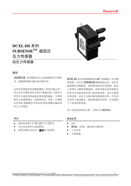
DCXL-DS系列SURSENSE TM超低压压力传感器硅压力传感器描述SURSENSE系列超低压压力传感器采用专利技术,能够降低输出偏差或共模误差。
这系列传感器采用显微机械加工的硅传感元件,该元件具有独特的应力集中-增强结构,可提供与所受压力成比例的高稳定度的线性输出。
与传统的压力传感器相比,因温度变化、受热、长期稳定性和位置敏感性等原因所造成的输出偏移误差已大大降低。
特点DCXL-DS系列传感器提供的mV比例输出,经过精密校准,并具有SURSENSE-增强的稳定性。
每台传感器都经过偏移量、满量程和热误差的校准,提高了流体压力测量的精确度。
这些高稳定的传感器具有符合行业标准装有端口的封装结构,其应力隔离有所改善,适合于安装印刷电路板的应用。
外壳设计采用了连盖板在一起的快速按扣结构,从而提高了产品质量和性能。
本产品获美国国家专利,专利号为6023978。
典型应用●温度补偿0℃至50℃[32℉至122℉] ●可以表压和差压范围供货●线性和滞后总误差<量程的±0.25% ●医疗● HV AC(供热,通风和空调系统)●工业仪表●环境监测DCXL-DS系列SURSENSE TM超低压压力传感器电气规格(25℃[77℉]时12Vdc激励)参数最小值典型值最大值单位Vdc16.0激励电压 3.012.0500零点偏移 -500µVmV21.020.0量程,除DCXL01DS外 19.0mV11.0量程,对DCXL01DS而言 9.010.0-150 - 150 µV偏置温度变化0℃至50℃[32℉至122℉]1,除DCXL01DS外-250 0 250 µV偏置温度变化0℃至50℃[32℉至122℉]1,对DCXL01DS而言-200 0 200 µV量程温度变化0℃至50℃[32℉至122℉]1%量程线性及滞后误差2- 0.05 0.2550[122]-℃[℉][32]补偿温度 0℃[℉]85[185]-工作温度 -25[-13]125[257]℃[℉][-40]-存贮温度 -40偏置受热变化3,除DCXL01DS外 -±50 - µV偏置受热变化3,对于DCXL01DS -±100 - µV偏置位置灵敏度(±1g)DCXL01DS -±50 - µV偏置位置灵敏度(±1g)DCXL05DS,DCXL10DS- ±10 - µV偏置位置灵敏度(±1g)DCXL20DS,DCXL30DS- ±5 - µV注:1.变化相对于25℃[77℉]而言。
- 1、下载文档前请自行甄别文档内容的完整性,平台不提供额外的编辑、内容补充、找答案等附加服务。
- 2、"仅部分预览"的文档,不可在线预览部分如存在完整性等问题,可反馈申请退款(可完整预览的文档不适用该条件!)。
- 3、如文档侵犯您的权益,请联系客服反馈,我们会尽快为您处理(人工客服工作时间:9:00-18:30)。
Honeywell S系列气体传感器使用指南
Honeywell S系列气体传感器使用
1. CLE三电极电化学传感器
对于三电极电化学传感器,每一个电极都有特殊的用途:
感应电极(S),用来氧化或还原气体,并产生与该气体浓度成比例的电流。
参考电极(R),用来稳定感应电极电动势。
对于没有偏压的传感器,感应电极电动势必须与参考电极电动势保持一致。
对于有偏压的传感器,感应电极电动势相对参考电极电动势有一定程度的偏离。
对电极(C),用来还原或氧化感应电极上被氧化或还原的物种,与感应电极一起形成电化学电路。
对电极的电动势允许随着气体浓度的增加而漂移。
对于三电极传感器,其电势是感应电极、参考电极和对电极电势之和。
所有的三电极电化学传感器在推荐的工作气体浓度范围内输出信号与气体浓度成线性关系,可以用下面的公式来计算:
输出信号(uA) = 灵敏度(uA/ppm) ×气体浓度(ppm) 对于无偏压的电化学传感器,感应电极和参考电极的电势差应该为零(<15 mV)。
对电极电动势允许漂移并随着感应电流的产生发生极化。
极化的程度取决于时间和气体浓度。
一旦极化电动势达到1.05 V,对电极就不再极化。
这意味着对一个无偏压电化学传感器,其最大理论电池电压是1.05 V。
对于有偏压的电化学传感器,参考电极和对电极电动势跟无偏压的电化学传感器一样,但是其感应电极电动势和参考电极电动势之差大于零。
推荐的偏压设置为:
ETO: +300 mV;
NH3: +300 mV
NO: +300 mV;
HCl: +200 mV;
O2: -600 mV.
因此,对于有偏压的电化学传感器,其最大理论电池电压是1.35 V。
实际上,在有偏压操作的电化学传感器上,其电池电压一般小于1.2 V。
为了保证Honeywell S系列电化学传感器能正常工作,必须给传感器一个合适的电路。
不论对于无偏压还是有偏压的电化学传感器,感应电极上被氧化的气体,如CO,H2S, PH3, ETO和HCN,其输出信号值是正值,相反的,感应电极上被还原的气体,如NO2和Cl2等,其输出信号值为负值。
为了保证Honeywell S系列无偏压三电极传感器在关闭电源的状态下也处于工作状态,我们用JFET Q1场效应晶体管把感应电极和参考电极短接。
同时,在U1上推荐一个小的偏置电压(<100uV)。
对于有偏压的电化学传感器,感应电极要在比参考电极高的多的电势下工作。
在有偏压的三电极电化学传感器电路中,与感应电极相连接的R load两端的电压不能太大,否则传感器的性能会受到影响。
这个电阻可以在电路噪声和响应时间之间达到一个较好的平衡。
Honeywell S 系列气体传感器使用指南
无偏压电化学传感器:
R load : 负载电阻,参考Honeywell S 系列电化学传感器datasheet 进行设置 R 3: 增益电阻,OUTPUT=输出信号x 增益电阻 Vcc 的典型值: 3.3 V V ref 的典型值: 1.2 V
JEFET Q1 任意可选
. Q1和Q1的控制电压取决于 Vcc, V ref 和栅电压。
带偏压的电化学传感器:
Rload: 负载电阻,参考Honeywell S 系列电化学传感器datasheet 进行设置 R 3: 增益电阻,OUTPUT=输出信号x 增益电阻 Vcc 的典型值: 3.3 V V ref 的典型值: 1.2 V
Honeywell S系列气体传感器使用指南
2. 可燃气体传感器
可燃气体传感器是一种微型催化氧化传感器,用于测量空气中的可燃气体。
可燃气体传感器由一对检测元件和补偿元件组成,每个元件放置于惠斯通电桥的一个桥臂上。
当没有可燃气体存在时,两个元件的电阻相等,电桥平衡,输出信号为零。
当有可燃气体存在时,检测元件将其氧化,产生的热量使其电阻增大,电桥不再平衡,产生与可燃气体浓度成正比关系的输出信号。
目前Honeywell S系列有2.3 V和4.25 V的4系列和7系列两种可燃气体传感器,下图是可燃气体传感器的推荐电路:。