英文版直流高压发生器说明书
直流发生器JZF-60kV-3mA说明书资料
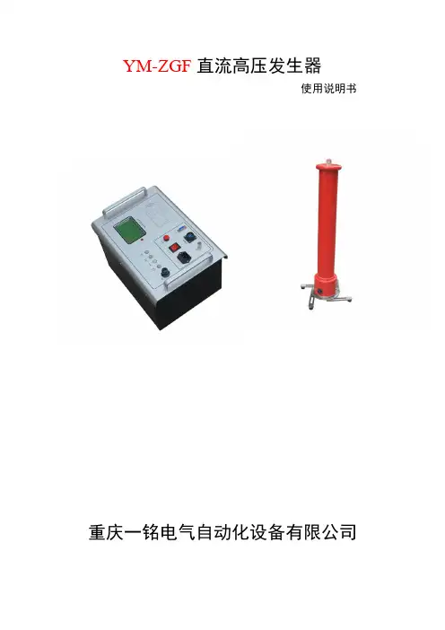
YM-ZGF直流高压发生器使用说明书重庆一铭电气自动化设备有限公司安全警告●使用直流高压试验器的工作人员必须是具有“高压试验上岗证”的专业人员。
●使用本仪器请用户必须按《电力安规》168条规定,并在工作电源进入试验器前加装两个明显断开点;当更换试品和接线时应先将两个电源断开点明显断开。
●试验前请检查试验器控制箱、倍压筒和试品的接地线是否接好。
试验回路接地线应按本说明书(图1)所示一点接地。
●对大电容试品的放电应经100Ω/V放电电阻棒对试品放电。
放电时不能将放电棒立即接触试品,应先将放电棒逐渐接近试品,至一定距离高空气间隙开始游离放电.有嘶嘶声:当无声音时可用随电棒放电,最后直接接上地线放电。
●直流高压在200kV及以上时,尽管试验人员穿绝缘鞋且处在安全距离以外区域,但由于高压直流离子空间电场分布的影响,会使几个邻近站立的人体上带有不同的直流电位。
试验人员不要互相握手或用手接触接地体等,否则会有轻微电击现象,此现象在干燥地区和冬季较为明显,但由于能量较小,一般不会对人造成伤害。
电缆试品试验时必须使用限流电阻!其它试品时不需要限流电阻!目录应用范围 (3)技术性能规格及工作方法 (4)使用说明 (5)一、面板说明 (6)二、倍压筒说明 (10)三、操作步骤 (11)四、注意事项 (12)五、数字微安表使用说明 (13)六、关于配套限流电阻使用参考 (14)七、放电棒的使用 (14)应用范围直流高压试验器主要适用于电力部门、工矿、冶金、钢铁等企业动力部门对氧化锌避雷器、电力电缆、变压器、断路器、发电机等高压电气设备进行直流耐压试验或直流泄露电流试验。
升压方式:手动升压.技术特点YM-ZGF型直流高压发生器。
应用AIPWM技术,对PWM技术的不准确线性度进行了调整,使仪器精度得到了大幅度提高。
并采用AI 技术屏幕设定过压保护和过流保护取代了数字拨盘开关只能设定电压值,不能设定电流值及电压飘移的问题。
0.75UDC1mA功能按钮,方便氧化锌避雷器试验,精度≤1%。
ZGF系列直流高压发生器使用说明书
ZGF系列直流高压发生器使用说明书目录一、简介 (1)二、主要技术性能 (1)三、工作原理框图 (2)四、使用说明 (2)五、操作步骤 (4)六、安全性试验检查 (4)七、典型泄漏电流曲线图 (4)八、直流试验部分接线示意图 (5)九、注意事项 (7)十、故障检查及处理 (8)十一、装箱单 (8)十二、可选附件 (8)一、简介ZGF系列直流发生器采用中高频倍压整电路,应用最新的PWM脉宽调制技术和大功率IGBT器件。
能连续调节直流高压、节能、电压调节线性度好、稳定、输出直流电压纹波非常小。
由于采用高频,电感、电容等滤波回路时间常数减小,有利于自动调节回路的品质和输出波形的改善及减小体积,便于携带。
各项技术指标符合中国现行标准ZGF24003-90《便携式直流高压发生器通用技术》的要求。
能同时测量泄漏电流,对绝缘损伤较小。
对于氧化避雷器75%电压有一键锁定,自动调节至75%电压,无须人工计算与调节。
某些指标优于《无间隙金属氧化避雷器》《GB11032-89》中规定。
严格按照企业标准《Q/WDS01-2000》生产。
并已通过《MC量制鄂字01000345号》制造许可。
二、主要技术性能工作电源 50Hz 220V ±10%电压测量数显±1% 1个字电流测量数显±1% 1个字电压稳定度随机波动,电源电压±10%时≤1‰如需要更高稳定度,可订制≤0.1‰直流高压脉动因数≤ 3%工作方式间断使用30分钟环境温度 -10℃≈50℃相对湿度<90%无凝露25℃时海拔高度 1500m以下三、工作原理图四、使用说明(一) 操作面板说明1、数显电流表:数字显示直流高压输出电流值;2、电源信号灯(绿色):表示仪器接通电源,处于待机状态;3、零位信号灯(黄色):本仪器有零位保护功能。
零位灯没亮,仪器无法启动;反之方可启动;4、工作信号灯(红色):高压回路接通后红灯亮,表示仪器可升压试验;5、保护闪光灯(红闪):在过流、过压或接线不对情况下,灯亮;6、数显电压表:显示直流高压输出电压值;7、复位及停止按钮,断高压回路及系统初始化复位。
直流高压发生器说明书

直流高压发生器说明书由于输入输出端子、测试柱等均有可能带电压,在插拔测试线、电源插座时,会产生电火花,小心电击,避免触电危险,注意人身安全!安全要求请阅读下列安全注意事项,以免人身伤害,并防止本产品或与其相连接的任何其它产品受到损坏。
为了避免可能发生的危险,本产品只可在规定的范围内使用。
只有合格的技术人员才可执行维修。
—防止火灾或人身伤害使用适当的电源线。
只可使用专用并且符合规格的电源线。
正确地连接和断开。
当测试导线与带电端子连接时,请勿随意连接或断开测试导线。
注意所有终端的额定值。
为了防止火灾或电击危险,请注意所有额定值和标记。
在进行连接之前,请阅读使用说明书,以便进一步了解有关额定值的信息。
使用适当的保险丝。
只可使用符合规定类型和额定值的保险丝。
避免接触裸露电路和带电金属。
有电时,请勿触摸裸露的接点和部位。
请勿在潮湿环境下操作。
请勿在易爆环境中操作。
-安全术语警告:警告字句指出可能造成人身伤亡的状况或做法。
目录一、概述 (5)二、工作原理 (5)三、性能特点 (6)四、技术指标 (7)五、操作说明 (8)六、使用注意事项及维护 (9)七、附件 (11)八、附录 (12)一. 概述ZGF系列直流高压发生器是电力部门和工矿企业对避雷器、电缆和高压设备进行直流耐压试验和泄漏电流试验的专用设备,本仪器是根据“中华人民共和国能源部标准”研制的换代产品,经国家高压计量站检验,符合《便携式直流高压发生器通用技术条件》(ZGF24003-90),某些指标优于《无间隙金属氧化物避雷器》(GB11032-89)的要求。
ZGF数字式直流高压发生器采用了九十年代新技术、新材料和新器件,具有输出功率大、体积小、重量轻的特点,有可靠的过压、过流及零位合闸保护功能,带0.75倍电压锁存功能,并配有时间继电器,能在试验中设置定时声讯报警。
整个仪器便于携带,操作方便,安全可靠,特别适用于电力部门现场试验。
二. 技术指标及使用条件1. 技术条件●电源:AC220V±10%,50Hz±1%●输出电压指示精度:<1级●输出电流指示精度:<1级●纹波系数:≤0.5%●0.75倍输出电压指示精度:<1级,带锁存2. 使用条件●相对湿度:25℃时不大于85%,无凝露●工作方式:间断使用30分钟●环境温度:- 10 40℃●海拔高度:1500m以下3. 保护功能●内部过压保护, 内部过流保护●外部过压保护(保护电压可整定), 外部过流保护或击穿保护●内部功率保护●非零点启动保护●定时声讯报警图1. 原理框图四. 面板说明ZGF数字式直流高压发生器由控制箱和倍压装置两部分组成,其控制面板布置如图2所示。
ZGS-C200kV 3mA 直流高压发生器 说明书
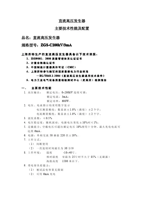
直流高压发生器主要技术性能及配置品名:直流高压发生器规格型号:ZGS-C200kV/3mA上海苏特生产的直流高压发生器具备以下技术资质:1、ISO9001:2000质量管理体系认证证书2、计量合格确认证书3、中国制造计量器具许可证(CMC)4、上海苏特参与编写的国家最新电力行业标准—DL/T848.1-2004《直流高压发生器通用技术条件》5、电力工业电气设备质量检验测试中心(武高所)检测报告一、主要技术性能1.高压输出:额定电压:0~200k V连续可调;额定电流:3mA;额定功率:600W。
2.电压、电流指示均采用数字显示电压测量精度:数显表±1.0%(满度)±2个字;电流测量精度:数显表±1.0%(满度)±2个字。
3.波纹系数:≤0.5%4.电压稳定度:随机波动,电源电压变化±10%时≤1%。
5.过载能力:空载电压可超出额定电压10%使用十分钟。
最大充电电流可达到6mA。
6.电源:单相交流50赫兹220伏±10%。
7.工作方式:(1)间断使用(2)一次连续时间最长为30分钟8.工作环境:温度-10~40℃。
相对湿度室温为25℃时不大于85%(无凝露)海拔高度1500米以下。
9.带电容负荷能力:(1)被试品电容量无限制(2)可用6mA充电10.结构特点:(1)丝绕环氧倍压筒。
(2)空气绝缘、无泄漏之虑。
11.操作箱特点(1)高精度0.75U DC1m A单触按钮(精度≤1.0%),最适合氧化锌避雷器试验。
(2)过压保护采用拨码设置,一目了然。
(3)立卧两用型国际标准机箱,现场更方便。
二、配置1.操作箱一只。
2.倍压筒一节。
3.全屏蔽高压微安表一块。
4.附件:专用接地线、电源线、中频引出线、高压屏蔽线各一根,放电棒一套,限流电阻一根。
5.外包装采用防震铝合金箱。
三、售后服务保障终身保修、三年内免费维修。
生产商:上海苏特电气有限公司ZGS-Q60kV/2mA直流高压发生器主要技术性能及配置三、主要技术性能12.高压输出:额定电压:0~60k V连续可调;额定电流:2mA;额定功率:120W。
ZGF直流高压发生器使用手册
ZGF直流高压发生器使用手册第一章引言1.1产品概述DGF直流高压发生器是一种用于产生高压直流电的设备,主要用途包括工业领域的电磁兼容性测试、高压电源供应以及实验室科研等。
本手册将介绍DGF直流高压发生器的基本原理、功能特点、操作注意事项等内容。
1.2产品特点(1)输出电压范围广,可调节范围为0至3000V;(2)稳定性高,能够稳定输出高压直流电;(3)具备保护装置,包括过压保护、短路保护等;(4)操作简单,配备LCD显示屏,支持触摸功能;(5)具备远程控制接口,可与计算机进行连接,实现远程操作。
第二章安全指引2.1使用环境DGF直流高压发生器应在环境温度5~40℃,相对湿度<80%的条件下使用。
使用过程中应避免受潮、高温、腐蚀性气体等恶劣环境。
2.2电源要求接入电源前,应检查电源电压与设备额定电压是否匹配。
如果电源过电压或低电压,不得开机使用,以防损坏设备或引发危险。
2.3设备连接在进行设备连接前,应先确保电源已关闭,并拔掉电源插头。
各种接线操作应准确无误,严禁乱接线或接反。
2.4防触电措施不得在设备工作时,触摸设备内的任何零部件。
如需清洗设备或更换零部件,需要先切断电源,待设备完全停止运行后再进行操作。
第三章设备操作3.1开机和关机(1)接通电源,插好电源插头;(2)按下电源开关,设备将开始自检过程,待显示屏亮起后,系统进入待机模式;(3)长按电源开关,设备将关机。
3.2设置输出电压(1)按下输出电压设置按钮,进入电压设置界面;(2)通过上下箭头键调节输出电压,确认后按下设置键保存;(3)再次按下输出电压设置按钮即可退出设置界面。
3.3输出电压控制(1)按下输出电压控制按钮,进入电压控制界面;(2)通过上下箭头键调节输出电压大小,按下确定键确认设定值;(3)再次按下输出电压控制按钮即可退出电压控制界面。
第四章故障排除4.1无法开机(1)检查电源插座是否通电,插头是否接触良好;(2)检查电源是否过电压或低电压;(3)检查设备是否有损坏,是否有零部件松动。
ZGF3mA300kV直流高压发生器操作说明
ZGF-3mA/300kV直流高压发生器操作说明我们的质量方针:以客户需求为宗旨,以科技创新为动力,以严格管理为保证,以国际水平为目标,为广大客户提供满意的产品和服务。
ZGF-3mA/300kV直流高压发生器具有多种保护功能,如:低压过流、低压过压、高压过流、高压过压、零位保护、不接地保护等。
故障取样采用专用的传感器,动作时间为纳秒级,光隔离元件也为纳秒级,动作时间一般在10微秒可完全关断直流主回路。
ZGF-3mA/300kV直流高压发生器技术参数:输出电压(kV) 200输出电流(mA) 3输出功率(W) 600充电电流(mA) 3控制箱重量(kg) 4.5倍压筒重量(kg) 7.9倍压筒规格(mm) Ф110 810电压测量误差 1%(满度)±1个字电流测量误差 1%(满度)±1个字过压整定误差过压保护采用拨码设置,一目了然(精度≤1.0%)0.75切换误差 ZGF-300kV/3mA直流高压发生器高精度0.75UDC-1mA单触按钮(精度≤1.0%)最适合氧化锌避雷器试验波纹系数≤0.5%工作方式间断使用:额定负载30分钟1.1倍额定电压使用:10分钟工作环境温度:-10℃~+40℃相对湿度:室温为25℃时不大于85%(无凝露)海拔高度:1500米以下带电容负荷被试品电容量无限制结构特点电气绝缘倍压筒空气绝缘、无泄漏之虑ZGF-3mA/300kV直流高压发生器操作说明:●控制箱上的显示灯、开关、旋钮等都已标注清晰,看此操作说明时,请参照控制箱的面板上元器件名称使用。
●高压塔底盘侧面有七芯插座为联接控制箱电缆之插座,底盘侧面有铜接线柱为接地端子作连接地线用。
●随附有高压屏蔽电流表为数显微安表,表顶端上的插孔为连接被试品的线插孔,同时也作为电源开关,不用时请拔掉插头,就自动关闭电源。
换电池时请将上盖镙丝打开,换好后请扣好盖用镙丝拧紧。
扁园表换电池时打开后盖。
1、将控制箱面板上的接地端子与高压塔的接地接线柱,用接地线连接在一起,并与现场或试验室的地线接牢。
直高发
电力检测设备
国自电气
五、高压倍压箱说明
1
1、顶帽 2、均压环
6
A向
2 A向
3、倍压筒7 4、机箱 5、接地柱 6、信号输入插座 7、测量输出插座
5 4
3 5
六、操作方法及步骤
1、 操 作 前 准 备
将 控 制 箱 的 信 号 输 出 电 缆 插 座 13 和 测 量 输 入 插 座 14 与 倍 压 装 置 电 缆 插 座 用 专 用 电 缆 连 接 好 ,使 用 前 检 查其完好性,联接电缆不应有短路和断路;倍压筒应 无凝露现象; 用 2.5 mm 2 以 上 的 铜 线 将 控 制 箱 接 地 与 倍 压装置接地端连接起来并可靠接地。 2、 水 阻 的 安 装 说 明 1) 在 每 次 试 验 前 将 水 阻 有 气 孔 一 端 拧 开 , 将 水 加 至 淹 没 导 电 杆 2/3 以 上 , 有 气 孔 的 一 端 朝 上 。
◇防止火灾或人身伤害
使用适当的电源线。只可使用本产品专用、并且符合本产品规格的电源线。
当测试导线与带电端子连接时, 请勿随意连接或断开测试导线。 正确地连接和断开。
注意所有终端的额定值。为了防止火灾或电击危险,请注意本产品的所有额定值
和标记。在对本产品进行连接之前,请阅读本产品使用说明书,以便进一步了解有关额定值 的信息。
电力检测设备
国自电气
7
电流指示 9 时间继电器 1 AC220V 10 定时 电源 3 4 5 6 过流 17 电压整定 电压指示
8
8
12
11 0.75 倍电压指示
13 信号输出 14 测量输入
20 锁存 18 电压粗调 19 电压细调
零位 过压
2 电源开关
RLT-Z直流高压发生器使用说明书
RLT-Z直流高压发生器使用说明书1 简介RLT-Z直流高压发生器由中频逆变倍压整流电路,专用的PWM脉宽调制芯片和高压大功率MOSFET器件组成,并含有0.75U电压输出、电流电压保护值设定、定时设定和保护时声光报警等功能。
仪器具有高精度、高稳定、便携式、功能全的特点。
各项技术指标符合我国现行标准ZB F24 003-90《便携式直流高压发生器通用技术条件》的要求。
注:“/”前方框处的数字表示仪器的最高输出工作电压,单位是kV,“/”后方框处的数字表示在最高输出电压时仪器可输出的最大电流,单位是mA。
2 原理方框图AC220V 输入A C/DC中频逆变器升压倍压输出RL调压采样保护显示图13 主要的系列产品型号规格60/ 2 60/5 60/10 120/2 120/5 200/2 200/5 300/2 300/5 400/2 400/3 (kV/mA)输出电压(kV)60 60 60 120 120 200 200 300 300 400 400 输出电流(mA) 2 5 10 2 5 2 5 2 5 2 3 输出功率(W)120 300 600 240 600 400 1000 600 1500 800 1200 倍压筒高约(m)0.4 0.4 0.4 0.6 0.6 0.9 0.9 1.25 1.25 1.5 1.5 附:用户有特殊要求的协商确定。
4 主要技术性能工作电源:电压220V±22V频率:50Hz或60Hz;显示精度:±1%;纹波系数:≤1%;工作方式:间断使用,每次不超过30min;环境温度:-10℃—50℃;相对湿度:≤90%,无凝露。
5 使用说明5.1 面板说明图2 面板示意图1.电源开关。
2.220V交流电源带保险输入插座。
3.七芯电缆输出插座,通过七芯电缆与倍压筒相接。
4.接地柱。
5.数显电压表:显示输出直流高压。
6.数显电流表:显示输出直流总电流(略大于高压微安表的读值)。
BLBLZGF直流高压发生器.
BL BLZGF直流高压发生器使用说明书武汉博朗恒业电气有限公司安全警告●使用直流高压发生器的工作人员必须是具有“高压试验上岗证”的专业人员。
●使用本仪器请用户必须按《电力安规》168条规定,并在工作电源进入试验器前加装两个明显断开点;当更换试品和接线时应先将两个电源断开点明显断开。
●试验前请检查试验器控制箱、倍压筒和试品的接地线是否接好。
试验回路接地线应按本说明书(图6)所示一点接地。
●对大电容试品的放电应经100Ω/V放电电阻棒对试品放电。
放电时不能将放电棒立即接触试品,应先将放电棒逐渐接近试品,至一定距离高空气间隙开始游离放电.有嘶嘶声:当无声音时可用随电棒放电,最后直接接上地线放电。
●直流高压在200kV及以上时,尽管试验人员穿绝缘鞋且处在安全距离以外区域,但由于高压直流离子空间电场分布的影响,会使几个邻近站立的人体上带有不同的直流电位。
试验人员不要互相握手或用手接触接地体等,否则会有轻微电击现象,此现象在干燥地区和冬季较为明显,但由于能量较小一般不会对人造成伤害。
一、简介BLZGF系列直流高压发生器是根据中国行业标准ZBF24003—90《便携式直流高压发生器通用技术条件》的要求,重新设计制造的第三代便携式直流高压发生器。
适用于电力部门、企业动力部门对氧化锌避雷器、磁吹避雷器、电力电缆、发电机、变压器、开关等设备进行直流高压试验。
BLZGF列直流高压发生器采用中频倍压电路。
率先应用最新的PWM脉宽调制技术和大功率IGBT器件。
并根据电磁兼容性理论,采用特殊屏蔽、隔离和接地等措施。
使直流高压试验实现了高品质、便携式并能承受额定电压放电而不损坏。
BLZGF系列直流高压发生器是我公司潜心研究而推出的新一代产品。
在保留了BLZGF 一些特点的基础上,作了如下重大改进:采用了电压大反馈,因此输出电压稳定度得到大幅度提高,电压漂移量较小;高压过压整定采用数字拨盘开关,能将整定电压值直观显示,并具有较高的整定精度;增设了高精度o.75UDc—1mA功能按纽,给氧化锌避雷器测量带来了极大的方便;输出电压调节采用单个多圈电位器,升压过程平稳,调节精度高,操作简单;为考虑用户不同的工作场所均能方便使用,本公司精心设计了立卧两用机箱:在现场打开箱盖即可卧式使用;在室内工作台上可立放使用。
直流高压发生器说明书
直流高压发生器一、概述本仪器具有较高的稳定度和可靠性,具有电压零位合闸保护、过电压保护及电流保护功能,能即时保护仪器和试品的安全。
本仪器还具有体积小、重量轻、便于携带、操作方便,连续可调安全可靠等特点,适用于● 供电部门现场直流高压试验,例如:电力电缆直流耐压和泄漏试验,磁吹避雷器和氧化锌避雷器电导电流和1mA参考电压试验如(Y1W/144/320W中性点避雷器、Y10W/204/530W电站型避雷器等)。
● 可作激光电源,还能用于静电喷涂、静电织绒等场合。
● 其它需要直流高压的场合。
凡我公司出厂的产品都经过严格质量检验,所有指标都优于中华人民共和国电力行业标准DL447.2-92的要求。
二、主要技术指标1、电压表准确度:≤2%2、电流表准确度:≤2%3、脉动因数S:≤3%4、工作电源:220V交流,50Hz5、工作方式:间断使用6、环境温度:0-40℃7、相对湿度:25℃时,不大与85%,无凝露三、工作原理图四、外观说明(1)操作端子1、接地端:引端应与倍压筒接地端及试品接地端联接为一点后,再与地网相连。
2、输出座:输出高频可调电源至倍压筒。
3、数显电压表:数字显示直流高压输出电压值。
4、数显75%电压表;数字显示直流高压输出75%倍电压值。
5、数显电流表:数字显示直流高压输出电流值(包括试品电流、电流引线电晕电流等)。
6、75%U锁定钮:按下锁定钮时指示灯亮,75%显示锁定。
7、过流保护,当输出电流达额定电流时,仪器自动切断高压,保护被试品。
8、过压保护,当输出电压达额定电流时,仪器自动切断高压,保护被试品9、高压开,当该灯亮时表示高压已启动。
10、高压关,当该灯亮时表示高压已关闭,此时没有高压输出。
11、红按钮,75%U锁定钮。
按下锁定钮时指示灯亮,75%显示锁定。
12、绿按钮:高压回路断开按钮,高压关指示灯亮。
13、红按钮:高压回路接通按钮,高压指示灯亮。
14、电压调节钮:顺时方向转动增加输出值。
- 1、下载文档前请自行甄别文档内容的完整性,平台不提供额外的编辑、内容补充、找答案等附加服务。
- 2、"仅部分预览"的文档,不可在线预览部分如存在完整性等问题,可反馈申请退款(可完整预览的文档不适用该条件!)。
- 3、如文档侵犯您的权益,请联系客服反馈,我们会尽快为您处理(人工客服工作时间:9:00-18:30)。
User manual book--High V oltage DC GeneratorWarningPeople who use of this product must have a "high-voltage test certificate".Please read the 168 regulation of "electric power regulatory" when you use this product,and install two apparently disconnected point between power and the tester, when replacing the tester or Connecting line, you should break the two disconnect point of power supply.Check tester control box, the high-voltage cylinder and the grounding wire is connected together before testing. The grounding wire should be connected rightly to the earth.The large capacitor loader must discharged through the resistor of 100Ω/ V. Don’t contact the rod resistor with the loader immediately, you should put the rod resistor close to the sample gradually, keep a certain distance, and then discharge with hiss. When there is no sound, we can use rod resistor finally discharge by connecting to earth.If the loader is a capacitive loader, before test you must connect with resistor.When the voltage is more than 200kV, although the test personnel wear insulated shoes and at a safe distance from the outside area, but because of the effects of high voltage DC ion distribution of space electric field, it can lead to different DC potential of standing people nearby. Don’t handshake each other or touch any grounding body, otherwise there will be a mild electric shock phenomenon, this phenomenon happens in dry areas and winter commonly, but it generates little energy, so it can do no harm to people.After finishing the test, you must connect the grounding wire to the end of high voltage output, and then you can remove the lead wire off.CATALOGIntroduction (4)Principle of operation (4)Technical parameter (4)Function (7)Operation steps (9)Fault resolve (13)Product complete sets (13)Quality assurance (14)Service Promise (14)Introduction The high voltage DC generator is a new product designed according to the new China electric power industry standard DL / T848.1-2004 "DC high voltage generator general technical conditions". This product is mainly used for DC endure experiment to high voltage device such as Electric Power Cooperation, Metallurgy, Iron and Steel enterprises.Principle of operationAC 220outTechnical parameter1. Technical character● The control box is used of aluminum alloy structure.● It uses the new technology such as PWM pulse-wide modulation, middlefrequency high voltage and high power IGBT device.● It uses voltage feedback; output stability is less than 3%.● Full range of voltage output, voltage regulating accuracy is less than 1%, thestability of voltage error is less than 1.5%, the voltage error ± (1.5% ±2 words), the current error ± (1.5% ± 2 words).●Raise voltage from zero voltage potentiometer.●The 0.75UDC/1mA function button is convenient for zinc oxide arrester test, andthe accuracy is ±(3%±2words).●Over voltage protection uses dialing number set, and the error is ±1%.●High voltage cylinder is used of new materials, lightweight and sturdy. It’s co atedwith special insulating materials, electrical performance and moisture-proof ability is good.●The product conforms to DL / T848.1-2004 technology requirements, and passedthe center test of electrical equipment quality inspection, strictly according to the enterprise standard.2. Technical parametersNote: As the product update, we don’t notice any more, according to the sample, the company reserves the right of interpretation.Function(1)Control box Panel1、Ground terminal: When testing, the grounding terminal of control box and high-voltage cylinder should be connected together, and then connected with the earth. 2、Output port is used for the connection of the control box and high-voltagecylinder . We only rotate the cable pressing plug clockwise in place when connecting, only rotate the cable plug anti-clockwise when broking.3、V oltage setting switch: Used for setting the over-voltage protection value. Thedisplay unit of dial switch is kV, set values is 1.1 times of the test voltage.4、Power input socket: A random configuration of power line and the power inputsocket. (AC voltage 220V±10%, socket with fuse.)5、Digital voltage meter: Digital display high voltage DC output voltage.6、Digital current meter: Digital display high voltage DC output current.7、Power switch: Forward press, the power is on, the red lights, conversely toshutdown.8、Yellow light button: This function is designed for zinc oxide arrester formeasurement of 0.75UDc1mA. It’s effective when the green lights. After pressing the button, output voltage reduce to the original 0.75%, and keeps this state. Press the red button, red light and green light all out, high pressure cuts off and exits0.75 times state.9、The green button: High-voltage output button, high voltage indicator lamps. In redlight state, press the green button, the green light and red light out, this means high voltage circuit is switched on, then we can raise voltage. It’s Effective that thisbutton must be on voltage regulating potentiometer zero state. If press the green button, the green light is bright red, at the same time the red light is brighter, but release the green button, green light out and red light, it means Internal protection circuit has been working.10、Red button: the red light shows that the power is switched on and the high voltageis cut off .In the green state ,press the red button, red light is bright, high voltage is cut off.11、V oltage adjusting potentiometer: The potentiometer is a multi-turn potentiometer.Rotate clockwise to boost, and conversely to Step-down. The potentiometer has the function of controlling electronic zero protection, so must firstly return to zerobefore boosting.(2)High-voltage cylinder1、High voltage terminals (connect Microampere meter and water resistance orcurrent-limiting resistor)2、Equipotential shielding for HV3、High-voltage cylinder4、Grounding terminal5、Intermediate frequency output terminal6、Base(3)Testing connectionOperation steps(If capacitive load, should access the current-limiting resistor)1、 Check integrity before using the tester, make sure that there is no circuit breakeror short circuit in connecting cable, and equipment without rupture damage.2、Put the control box and High-voltage cylinder in place, then respectively connectpower line, control cable and grounding line ,protect all grounding wire separatelyconnecting to the sample point (one point tie to the earth ).Forbids the groundingwire connected in series. For this purpose, you should use the DHV specialgrounding wire.3、Keep power switch off and check voltage potentiometer at zero. Over voltageprotection setting value is generally 1.1 times of the testing voltage.4、No load ,step-up to verify the sensitivity of over voltage protection setting.5、Put power on, the red light, it means power on.6、Press the green button, then the green light, it means high voltage is outputting7、Regulate pressure regulating potentiometer clockwise direction smoothly, outputend is raised from zero to a desired voltage, according to the prescribed timerecording current meter readings, and check the control box and high voltageoutput line has no abnormal phenomenon or sound.8、 Reduce voltage ,regulate pressure regulating potentiometer to zero, then press )the red button, cut off the high voltage and then turn the power switch off.9、To test for leakage and DC voltage endurance, check test confirmation testerwithout exception, you can start test for leakage and DC voltage endurance test.Connect the test items and grounding wire, and then can open power s before thereis no mistake.10、Raise to the required voltage or current. The suitable raising speed is 3 - 5kV testvoltage per second. For large capacitance, we need to monitor of ammetercharging current not exceed the maximum charging current tester while raisingvoltage. For small capacitive products such as zinc oxide arrester, lightningarrester, we firstly raise to a desired voltage (current) at 95%, then slowly raiseto a desired voltage (current).From the digital display meter, we can read outvoltage (current) value. For zinc oxide arrester 0.75UDC - 1mA measurement, we firstly rise to UDC1mA voltage value, and then press the yellow button, when the voltage is reduced to the original 75%, and remains in this state. At this time, current value can be read. After the measurement, regulate pressure regulating potentiometer anticlockwise to zero, press the green button. Press green button.When you need raising voltage againYou can use external High Voltmeter to measure the output voltage if necessary.11、Reduce voltage and turn off the power after finish testing.12、Several methods for measuringa. Normal, when the wires are connected, suspend wires of tester, rising to thetesting voltage with no load ,Read stray current I’first, and then try to read the total currentⅠ1 with load, sample leakage current: Io =Ⅰ1—I’b.When we need an accurate measurement of sample leakage current, we should connect the high voltage micro ammeter to the high side (see below).Microampere meter must have a metal shielding; shielding line should be connected with test. The shielding of High voltage lead should be closely connected with end shielding. If the sample surface is dirty, we should exclude effect of samplesurface leakage current. In samples of high potential end, several times around with bare metal cords (see below).c.For sample such as zinc oxide, magnetic blow-out arrester, the grounding end can be breaked up; also can measure by connecting ammeter to the bottom (ground potential side) of test items. when we exclude effect of sample surface leakage current,we can use soft of bare copper wire in the sample to end the last laps around the shield ,and connect shielding line (see below)13、For small capacitive products ,such as zinc oxide and lightning arrester ,itdischarges quickly through pressure resistance. For large capacitive products such as cable, while test voltage self discharging to the test voltage is below 20%, then it can discharge by supporting the discharging rod. Keep connect the grounding wire to the capacitive products before voltage discharging completely, and then we can remove high voltage lead and other wire.14、If green light is off, red light is bright, voltage is dropping, which is relatedprotection to the product .You should turn off the power switch, panel lights are not bright. Turn the pressure regulating potentiometer to zero position, while low voltage capacitor discharging completely, then open the power switch a minute later. If you start a no loading test again, you can begin raising voltage test before checking all situations.Fault resolveComplete sets of products1. Control box 12. High-voltage cylinder 13. Use’s manual book 14. Fuse some5. Power cable 16. Special grounding wire 17. Discharging rod 18. Water resistance or current limiting resistor 19. Microampere ammeter 1Quality assurance1. The equipment made by the company can meet the requirements of the buyer, andprovide free pre-sale technical services.2. Products of the company have effective inspection and control, strictly productaccording to ISO9001 quality system of production service.3. The quality of our products is according to the standards of our company andrelevant national standards.Service PromiseThe product’s warrant time is one year, the implementation of "Three Guarantees", life-long repairing, all of the equipment of the company quality problem, we can provide free repair in the warranty period. Improper operation due to the user or accidental damage, we can provide preferential services. We’ll be looking forward to your valuable opinions to our products.。