SIIS1142 电压稳压器
智能电源1500VA 1350W 120V线型矢波无interrupt UPS - 8插孔,网络卡选

SmartPro 1500VA 1350W 120V Line-Interactive Sine Wave UPS - 8 Outlets, Network Card Option, LCD, USB, DB9, 2U Rack/TowerMODEL NUMBER:SMART1500RM2UProvides complete battery backup and pure sine wave power output for data centers, VoIP systems and network closets.Features1.5kVA/1.35kW/120V Battery Backup for PC Networks, Security Systems or Digital SignageThis rack-mount line-interactive UPS system provides reliable battery backup and AC power protection against blackouts, brownouts, surges and line noise that can damage your IT equipment or destroy data. The SMART1500RM2U is ideal power management for small networks, wiring closets, security systems, telecom, high-end PC gaming, digital signage equipment and other professional applications, including retail, casino and hotel/motel management.Reliable Battery Backup Keeps You Operational Through Power OutagesThe field-replaceable, hot-swappable VRLA battery modules allow you to work through short power failures and give you enough time to safely save files and shut down your system in case of a prolonged blackout. Switchover from line to battery power happens within milliseconds to maintain continuous operation of connected equipment without interruption or rebooting.Optional LX Platform Network Management Card Allows Remote Access 24/7The WEBCARDLX network interface (sold separately) enables full remote configuration and management, including load shedding, reboots of connected equipment and safe shutdowns. The IP-based Auto Probe feature ensures continuous network uptime by communicating with other network devices, detecting lost connectivity and automatically rebooting IT equipment. Optional EnviroSense2 modules (E2MT, E2MTDO and E2MTHDI, all sold separately) provide a variety of environmental monitoring and control options.NEMA Outlets Protect Your Connected ComponentsEight NEMA 5-15R outlets provide connected equipment with pure sine wave AC output and protect connected equipment against damaging surges and line noise. Four outlets are split into two independently switchable load banks that let you shed non-critical loads to extend runtime for critical loads.Automatic Voltage Regulation (AVR) Corrects Low- and High-Voltage ConditionsAVR protects your equipment from incremental hardware damage, data loss and performance problems caused by brownouts. The SMART1500RM2U maintains regulated 120V nominal output during brownouts and overvoltages from 83V to 147V while keeping the battery fully charged and ready to take over in case of power failure.HighlightsProtects equipment againstblackouts, brownouts, transientsurges and line noiseqKeeps equipment running during outages to allow time for filesaves and safe shutdownqMaintains continuous 120Vnominal output duringbrownouts and overvoltagesqOptional WEBCARDLX network interface allows you 24/7 remote access from anywhereqInteractive LCD allows real-time monitoring of voltage, batterystatus and other dataqPackage Includes1500VA 1350W 120V Line-Interactive UPSqUSB cableqDB9 cableqEPO cableqRack-mounting hardwareqOwner’s manualqSpecificationsPremium Protection from EMI/RFI Line Noise Helps Your Equipment Perform BetterThis UPS system filters out disruptive electromagnetic and radio frequency interference that can inflict hardware damage or data loss. This EMI/RFI filtering also helps your connected components perform better and last longer.Intuitive Front-Panel Interface for Convenient UPS Operation and MonitoringThe large LCD indicates a variety of UPS operational conditions, including voltage, runtime, load, battery and operating mode. The control panel rotates to accommodate both rack-mount and tower configurations. An audible alarm indicates loss of utility power, overload or low battery.Advanced Communications Ports Allow for Automatic ShutdownsRS-232 and HID-compliant USB ports connect to a computer running free downloadable PowerAlert®software to enable safe unattended system shutdown in case of a prolonged power failure. An EPO port supports emergency shutdown in large facilities. Cables are included.Versatile Installation OptionsHardware is included for mounting the SmartPro UPS system in 2U of space in an EIA-standard 19-inch 4-post rack. Using optional mounting accessories (sold separately), you can adapt the SMART1500RM2U for 2-post (2POSTRMKITWM) or tower (2-9USTAND) installation. The 10-foot power cord with NEMA 5-15P plug connects to any compatible AC outlet.© 2023 Eaton. All Rights Reserved. Eaton is a registered trademark. All other trademarks are the property of their respective owners.。
德力西 JS14P 系列时间继电器 说明书
本系列时间继电器,均采用中规模集成电路、 LED发光 二极管指示,数字拔码开关预置,具有设定方便,工作稳定 可靠,延时精度高,体积小等特点。
三、技术特征
3.1 额定绝缘电压Ui: AC380V 3.2 额定冲击耐受电压Uimp:AC2.5kV 3.3 额定控制电源电压Us:AC:380V、220V、127V、110V、 36V、24V、12V;DC:220V、127V、110V、36V、24V、12V; AC/DC24V~48V;AC/DC100V~240V。 3.4 使用类别下各个额定工作电压Ue/额定工作电流Ie: AC-15 Ue:AC380V,Ie:0.95A;Ue:AC240V,Ie:1.5A;
四、产品外形及安装尺寸
8-Φ4为板后 接线时的穿线孔
单位:(mm)
45.5max
97.5max
2-Φ 4.5
55±0.5 ≥90
84.5max 35.5±0.30
JS14P、JS14P-D外形尺寸图
52.5max
114max
பைடு நூலகம்10
装置式安装尺寸图
(或采用35mm标准导轨安装) 45+00.50
77+00.50
确属产品本身质量问题的产品,请与当地经销公司或 我公司联系。
七、运输与贮存
产品贮存和运输过程中不受到雨雪的侵袭,及挤压,在贮 存时应放置在空气流通,相对湿度(25℃±5℃)不超过90%。 温度下限为-25℃,温度上限为+55℃。
八、开箱及检查
打开外包装纸盒,检查包装盒内应有,使用说明书。
九、订货须知
-6-
额定控制电源电压U s:见3.3 延 时 时 间:见 表 安装形式:不标注表示装置式;M标 示面板式 延时型式规格代号:无标注为通电延时;
GK系列高可靠交流变频稳压电源用户手册说明书

GK 系列高可靠交流变频稳压电源用户手册
前言
感谢购置远方 GK 系列高可靠交流变频稳压电源。本用户手册包含仪器功能、 操作过程以及安全规定等,为了确保正确使用本仪器,在操作仪器前请仔细阅读 手册。请妥善保存手册,以便碰到问题时能快速查阅。
注意:
本公司奉行不断完善改进产品的宗旨,因此手册内容有可能改变,恕不 另行通知。
用前请先确认供电电网的电压范围,然后将后面板上的供电选择器开关打在 正确的位置,否则可能造成仪器无法正常工作甚至毁坏。(115V 档对应电网 供电范围为 99V~121V;230V 档对应电网供电范围为 198V~242V) 6、 接地线应尽量选择 8AWG 号线或与仪器地线相同粗细的导线,严禁将电源中 线作为接地线使用。若中线与地线间压差大于 5V,请重新安装接地线系统, 以维护设备安全。 7、 接线完毕后,确认连接线路正确无误后方可开机使用。当仪器开启或测试时, 禁止切换后面板的电源输入选择器开关,否则会造成仪器内部损坏甚至危及 操作人员的安全。 8、 仪器在运行状态时,避免震动和冲击,以免电源受到损坏。严禁人体触及带 电部位,防止电击。 9、 确保仪器的输出处于关断状态后方可关机。 10、 请保持仪器的清洁,避免从通风口进入异物。 11、 非专业人员请勿打开机盖,以防触电及损坏仪器。
Zone, Hangzhou(310053), China Tel :86-571-86699998 Fax :86-571-86673318 E-mail:Sales@ 销售专箱
SA1117C 1A中文资料
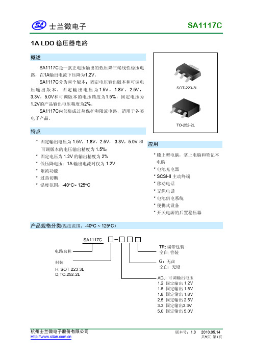
SA1117C1A LDO 稳压器电路概述SA1117C是一款正电压输出的低压降三端线性稳压电 路,在1A输出电流下压降为1.2V。
SA1117C分为两个版本:固定电压输出版本和可调电 压 输 出 版 本 , 固 定 输 出 电 压 为 1.5V , 1.8V , 2.5V , 3.3V , 5.0V 和可调版本的电压精度为 1.5% ,固定电压为 1.2V的产品输出电压精度为2%。
SA1117C内部集成过热保护和限流电路,适用于各类 电子产品。
TO-252-2L SOT-223-3L特点* 固定输出电压为 1.5V,1.8V,2.5V, 3.3V,5.0V 和 可调版本的电压输出精度为 1.5%; * 固定电压为 1.2V 的输出精度为 2% * 低压降电压:1A 输出电流时仅为 1.2V * 限流功能 * 过热切断 * 温度范围:-40°C~ 125°C应用* 膝上型电脑,掌上电脑和笔记本 电脑 * 电池充电器 * SCSI-II 主动终端 * 移动电话 * 无绳电话 * 电池供电系统 * 便携式设备 * 开关电源的后置稳压器产品规格分类(温度范围:-40°C ~ 125°C)杭州士兰微电子股份有限公司版本号:1.02010.05.14 共9页 第1页SA1117C产品名称 SA1117CH-ADJTR SA1117CH-1.2TR SA1117CH-1.5TR SA1117CH-1.8TR SA1117CH-2.5TR SA1117CH-3.3TR SA1117CH-5.0TR SA1117CD-ADJ SA1117CD-ADJTR SA1117CD-1.2 SA1117CD-1.2TR SA1117CD-1.5 SA1117CD-1.5TR SA1117CD-1.8 SA1117CD-1.8TR SA1117CD-2.5 SA1117CD-2.5TR SA1117CD-3.3 SA1117CD-3.3TR SA1117CD-5.0 SA1117CD-5.0TR TO-252-2L SOT-223-3L 封 装 打印名称 SA1117CH-ADJ SA1117CH-1.2 SA1117CH-1.5 SA1117CH-1.8 SA1117CH-2.5 SA1117CH-3.3 SA1117CH-5.0 SA1117CD-ADJ SA1117CD-ADJ SA1117CD-1.2 SA1117CD-1.2 SA1117CD-1.5 SA1117CD-1.5 SA1117CD-1.8 SA1117CD-1.8 SA1117CD-2.5 SA1117CD-2.5 SA1117CD-3.3 SA1117CD-3.3 SA1117CD-5.0 SA1117CD-5.0 材料 无铅 无铅 无铅 无铅 无铅 无铅 无铅 无铅 无铅 无铅 无铅 无铅 无铅 无铅 无铅 无铅 无铅 无铅 无铅 无铅 无铅 包装 编带 编带 编带 编带 编带 编带 编带 料管 编带 料管 编带 料管 编带 料管 编带 料管 编带 料管 编带 料管 编带杭州士兰微电子股份有限公司版本号:1.02010.05.14 共9页 第2页SA1117C内部框图3VINTSDCurrent Limit VOUT Fixed: F1 and F2 connect, disconnect A F2 A Adj: A connect, F1 and F2 disconnect 1 ADJ/GNDBandGap F12极限参数参 输入工作电压 引脚温度 (焊接5秒) 工作结温范围 储存温度 功耗 ESD能力 (最小值) 数 符号 VIN TLead TJ Tstg PD ESD 范 围 单位 V °C °C °C mW V15 260 150 -65 ~ +150 内部限制 (注1) 2000注1:最大允许功耗是最大工作结温TJ (max),结对空热阻θJA 和环境温度Tamb的函数。
VK1072D瓦斯表电熨斗泡脚机LCD驱动,段码液晶显示驱动IC(芯片)FAE技术支持

VK1072D瓦斯表/电熨斗/泡脚机LCD驱动,段码液晶显示驱动IC(芯片)FAE技术支持概述:VK1072D是一个点阵式存储映射的LCD驱动器,可支持最大72点(18SEGx4COM)的LCD屏,也支持2COM和3COM的LCD屏。
单片机可通过三条通信线配置显示参数和发送显示数据,也可通过指令进入省电模式。
特点:•工作电压 2.4-5.2V•许硕,Q 191-888-5898•电188-****2398•内置256 kHz RC振荡器(上电默认)•偏置电压(BIAS)可配置为1/2、1/3• COM周期(DUTY)可配置为1/2、1/3、1/4•内置显示RAM为18x4位•省电模式(通过关显示和关振荡器进入)• 3线串行接口• VLCD脚调节LCD电压•软件配置LCD显示参数•写命令和写数据2种命令格式•写显示数据地址自动加1• VLCD脚提供LCD驱动电压(<VDD)•封装:SSOP28(150mil)(9.9mm×3.9mm PP=0.635mm)KPP2571——————————————————————LCD驱动IC-标准系列VK1024B 2.4~5.2V SEG*COM:6*4、6*3、6*2 偏置电压1/2 1/3 S0P-16VK1056B 2.4~5.2V SEG*COM:14*4、14*3/14*2偏置电压1/2 1/3 SOP/SSOP24VK1072B 2.4~5.2V SEG*COM:18*4、18*3、18*2偏置电压1/2 1/3 SOP28VK1072C 2.4~5.2V SEG*COM:18*4、18*3、18*2偏置电压1/2 1/3 SOP28VK1072D 2.4~5.2V SEG*COM:18*4、18*3、18*2偏置电压1/2 1/3 SSOP28VK1088B 2.4~5.2V SEG*COM:22*4、22*3、22*2 偏置电压1/2 1/3 QFN32(4*4)VK0192 2.4~5.2V 24seg*8com 偏置电压1/4 LQFP-44VK0256 2.4~5.2V 32seg*8com 偏置电压1/4 QFP-64VK0256B 2.4~5.2V 32seg*8com 偏置电压1/4 LQFP-64VK0256C 2.4~5.2V 32seg*8com 偏置电压1/4 LQFP-52VK1621 2.4~5.2V SEG*COM:32*4、32*3、32*2偏置电压1/2 1/3 LQFP44/48/SSOP48/SKY28/DICE裸片VK1622 2.4~5.5V 32seg*8com偏置电压1/4 LQFP44/48/52/64/QFP64/DICE裸片VK1623 2.4~5.2V 48seg*8com偏置电压1/4 LQFP-100/QFP-100/DICE裸片VK1625 2.4~5.2V 64seg*8com偏置电压1/4 LQFP-100/QFP-100/DICE 裸片VK1626 2.4~5.2V 48seg*16com偏置电压1/5 LQFP-100/QFP-100/DICE 裸片——————————————————————————————————LCD驱动IC-抗干扰系列VK2C21A 2.4~5.5V 20seg*4com 16*8 偏置电压1/3 1/4 I2C通讯接口SOP-28VK2C21B 2.4~5.5V 16seg*4com 12*8 偏置电压1/3 1/4 I2C通讯接口SOP-24VK2C21C 2.4~5.5V 12seg*4com 8*8 偏置电压1/3 1/4 I2C通讯接口SOP-20VK2C21D 2.4~5.5V 8seg*4com 4*8 偏置电压1/3 1/4 I2C通讯接口SOP-16VK2C22A 2.4~5.5V 44seg*4com 偏置电压1/2 1/3 I2C通讯接口LQFP-52VK2C22B 2.4~5.5V 40seg*4com 偏置电压1/2 1/3 I2C通讯接口LQFP-48VK2C23A 2.4~5.5V 56seg*4com 52*8 偏置电压1/3 1/4 I2C通讯接口LQFP-64VK2C23B 2.4~5.5V 36seg*8com 偏置电压1/31/4 I2C通讯接口LQFP-48VK2C24 2.4~5.5V 72seg*4com 68*8 60*16 偏置电压1/3 1/4 1/5 I2C通讯接口LQFP-80超低功耗LCD液晶控制器及驱动系列:VKL060 2.5~5.5V 15seg*4com 偏置电压1/2 1/3 I2C通讯接口 SSOP-24VKL128 2.5~5.5V 32seg*4com 偏置电压1/2 1/3 I2C通讯接口 LQFP-44VKL144A 2.5~5.5V 36seg*4com 偏置电压1/2 1/3 I2C通讯接口 TSSOP-48VKL144B 2.5~5.5V 36seg*4com 偏置电压1/2 1/3 I2C通讯接口 QFN48L (6MM*6MM)LCD驱动IC-静态显示系列:VKS118 2.4~5.2V 118seg*2com 偏置电压-- 4线通讯接口 LQFP-128VKS232 2.4~5.2V 116seg*2com 偏置电压1/1 1/2 4线通讯接口 LQFP-128LED数显驱动-3线/4线接口VK1628---通讯接口:STb/CLK/DIO 电源电压:5V(4.5~5.5V) 驱动点阵:70/52共阴驱动:10段7位/13段4位共阳驱动:7段10位按键:10x2 封装SOP28VK1629---通讯接口:STb/CLK/DIN/DOUT 电源电压:5V(4.5~5.5V) 驱动点阵:128共阴驱动:16段8位共阳驱动:8段16位按键:8x4 封装QFP44VK1629A---通讯接口:STb/CLK/DIO 电源电压:5V(4.5~5.5V) 驱动点阵:128共阴驱动:16段8位共阳驱动:8段16位按键:--- 封装SOP32VK1629B---通讯接口:STb/CLK/DIO 电源电压:5V(4.5~5.5V) 驱动点阵:112共阴驱动:14段8位共阳驱动:8段14位按键:8x2 封装SOP32VK1629C---通讯接口:STb/CLK/DIO 电源电压:5V(4.5~5.5V) 驱动点阵:120共阴驱动:15段8位共阳驱动:8段15位按键:8x1 封装SOP32VK1629D---通讯接口:STb/CLK/DIO 电源电压:5V(4.5~5.5V) 驱动点阵:96共阴驱动:12段8位共阳驱动:8段12位按键:8x4 封装SOP32VK1640---通讯接口: CLK/DIN 电源电压:5V(4.5~5.5V) 驱动点阵:128共阴驱动:8段16位共阳驱动:16段8位按键:--- 封装SOP28VK1640A---通讯接口: CLK/DIN 电源电压:5V(4.5~5.5V) 驱动点阵:128共阴驱动:8段16位共阳驱动:16段8位按键:--- 封装SSOP28VK1640B---通讯接口: CLK/DIN 电源电压:5V(4.5~5.5V) 驱动点阵:96共阴驱动:8段12位共阳驱动:12段8位按键:--- 封装SSOP24VK1650---通讯接口: SCL/SDA 电源电压:5V(3.0~5.5V)共阴驱动:8段4位共阳驱动:4段8位按键:7x4 封装SOP16/DIP16VK1651---通讯接口: SCL/SDA 电源电压:5V(3.0~5.5V)共阴驱动:7段4位共阳驱动:4段7位按键:7x1 封装SOP16/DIP16VK1616---通讯接口: 三线串行电源电压:5V(3.0~5.5V)显示模式:7段4位按键:7x1 封装SOP16/DIP16VK1668---通讯接口:STb/CLK/DIO 电源电压:5V(4.5~5.5V) 驱动点阵:70/52共阴驱动:10段7位/13段4位共阳驱动:7段10位按键:10x2 封装SOP24 VK6932---通讯接口:STb/CLK/DIN 电源电压:5V(4.5~5.5V) 驱动点阵:128共阴驱动:8段16位17.5/140mA 共阳驱动:16段8位按键:--- 封装SOP32 LED数显驱动-12C接口VK16K33A/B/C---通讯接口:SCL/SDA 电源电压:5V(4.5V~5.5V)驱动点阵:128/96/64共阴驱动:16段8位/12段8位/8段8位共阳驱动:8段16位/8段12位/8段8位按键:13x3 10x3 8x3封装SOP20/SOP24/SOP28VK1618---带键盘扫描接口的LED驱动控制专用电路,内部集成有MCU数字接口、数据锁存器、键盘扫描等电路共阴驱动:5段7位/6段6位/7段5位/8段4位共阳驱动:7段5位/6段6位/5段7位/4段8位按键:5x1 封装SOP18/DIP18VK1S68C---LED驅動IC 10x7/13x4段位 10段7位/11段6位共阴10x2按键,封装SSOP24VK1Q68D---LED驅動IC 10x7/13x4段位 10段7位/11段6位共阴10x2按键,封装QFP24VK1S38A---LED驱动IC 8段×8位封装SSOP24VK1638--- LED驱动IC 共阴10段8位共阳8段10位封装SOP32 ——————————————————————————————————触摸触控IC系列简介如下:标准触控IC-电池供电系列:VKD223EB --- 工作电压/电流:2.0V-5.5V/5uA-3V 感应通道数:1 通讯接口最长响应时间快速模式60mS,低功耗模式220ms 封装:SOT23-6VKD223B --- 工作电压/电流:2.0V-5.5V/5uA-3V 感应通道数:1通讯接口最长响应时间快速模式60mS,低功耗模式220ms 封装:SOT23-6VKD233DB ---工作电压/电流:2.4V-5.5V/2.5uA-3V 1感应按键封装:SOT23-6 通讯接口:直接输出,锁存(toggle)输出低功耗模式电流2.5uA-3VVKD233DH ---工作电压/电流:2.4V-5.5V/2.5uA-3V 1感应按键封装:SOT23-6 通讯接口:直接输出,锁存(toggle)输出有效键最长时间检测16SVKD233DS ---工作电压/电流:2.4V-5.5V/2.5uA-3V 1感应按键封装:DFN6通讯接口:直接输出,锁存(toggle)输出低功耗模式电流2.5uA-3VVKD233DR ---工作电压/电流:2.4V-5.5V/1.5uA-3V 1感应按键封装:DFN6通讯接口:直接输出,锁存(toggle)输出低功耗模式电流1.5uA-3VVKD233DG --- 工作电压/电流:2.4V-5.5V/2.5uA-3V 1感应按键封装:DFN6通讯接口:直接输出,锁存(toggle)输出低功耗模式电流2.5uA-3VVKD233DQ --- 工作电压/电流:2.4V-5.5V/5uA-3V 1感应按键封装:SOT23-6通讯接口:直接输出,锁存(toggle)输出低功耗模式电流5uA-3VVKD233DM --- 工作电压/电流:2.4V-5.5V/5uA-3V 1感应按键封装:SOT23-6 (开漏输出)通讯接口:开漏输出,锁存(toggle)输出低功耗模式电流5uA-3VVKD232C--- 工作电压/电流:2.4V-5.5V/2.5uA-3V 感应通道数:2 封装:SOT23-6 通讯接口:直接输出,低电平有效固定为多键输出模式,內建稳压电路——————————————————————————————————MTP触摸IC——VK36N系列抗电源辐射及手机干扰:VK3601L --- 工作电压/电流:2.4V-5.5V/4UA-3V3 感应通道数:1 1对1直接输出待机电流小,抗电源及手机干扰,可通过CAP调节灵敏封装:SOT23-6VK36N1D --- 工作电压/电流:2.2V-5.5V/7UA-3V3 感应通道数:1 1对1直接输出触摸积水仍可操作,抗电源及手机干扰,可通过CAP调节灵敏封装:SOT23-6 VK36N2P --- 工作电压/电流:2.2V-5.5V/7UA-3V3 感应通道数:2 脉冲输出触摸积水仍可操作,抗电源及手机干扰,可通过CAP调节灵敏封装:SOT23-6 VK3602XS ---工作电压/电流:2.4V-5.5V/60UA-3V 感应通道数:2 2对2锁存输出低功耗模式电流8uA-3V,抗电源辐射干扰,宽供电电压封装:SOP8VK3602K --- 工作电压/电流:2.4V-5.5V/60UA-3V 感应通道数:2 2对2直接输出低功耗模式电流8uA-3V,抗电源辐射干扰,宽供电电压封装:SOP8VK36N2D --- 工作电压/电流:2.2V-5.5V/7UA-3V3 感应通道数:2 1对1直接输出触摸积水仍可操作,抗电源及手机干扰,可通过CAP调节灵敏封装:SOP8VK36N3BT ---工作电压/电流:2.2V-5.5V/7UA-3V3 感应通道数:3 BCD码锁存输出触摸积水仍可操作,抗电源及手机干扰,可通过CAP调节灵敏封装:SOP8VK36N3BD ---工作电压/电流:2.2V-5.5V/7UA-3V3 感应通道数:3 BCD码直接输出触摸积水仍可操作,抗电源及手机干扰,可通过CAP调节灵敏封装:SOP8VK36N3BO ---工作电压/电流:2.2V-5.5V/7UA-3V3 感应通道数:3 BCD码开漏输出触摸积水仍可操作,抗电源及手机干扰封装:SOP8/DFN8(超小超薄体积)VK36N3D --- 工作电压/电流:2.2V-5.5V/7UA-3V3 感应通道数:3 1对1直接输出触摸积水仍可操作,抗电源及手机干扰封装:SOP16/DFN16(超小超薄体积)VK36N4B ---工作电压/电流:2.2V-5.5V/7UA-3V3 感应通道数:4 BCD输出触摸积水仍可操作,抗电源及手机干扰封装:SOP16/DFN16(超小超薄体积)VK36N4I---工作电压/电流:2.2V-5.5V/7UA-3V3 感应通道数:4 I2C输出触摸积水仍可操作,抗电源及手机干扰封装:SOP16/DFN16(超小超薄体积)VK36N5D ---工作电压/电流:2.2V-5.5V/7UA-3V3 感应通道数:5 1对1直接输出触摸积水仍可操作,抗电源及手机干扰封装:SOP16/DFN16(超小超薄体积)VK36N5B ---工作电压/电流:2.2V-5.5V/7UA-3V3 感应通道数:5 BCD输出触摸积水仍可操作,抗电源及手机干扰封装:SOP16/DFN16(超小超薄体积)VK36N5I ---工作电压/电流:2.2V-5.5V/7UA-3V3 感应通道数:5 I2C输出触摸积水仍可操作,抗电源及手机干扰封装:SOP16/DFN16(超小超薄体积)VK36N6D --- 工作电压/电流:2.2V-5.5V/7UA-3V3 感应通道数:6 1对1直接输出触摸积水仍可操作,抗电源及手机干扰封装:SOP16/DFN16(超小超薄体积)VK36N6B ---工作电压/电流:2.2V-5.5V/7UA-3V3 感应通道数:6 BCD输出触摸积水仍可操作,抗电源及手机干扰封装:SOP16/DFN16(超小超薄体积)VK36N6I ---工作电压/电流:2.2V-5.5V/7UA-3V3 感应通道数:6 I2C输出触摸积水仍可操作,抗电源及手机干扰封装:SOP16/DFN16(超小超薄体积)VK36N7B ---工作电压/电流:2.2V-5.5V/7UA-3V3 感应通道数:7 BCD输出触摸积水仍可操作,抗电源及手机干扰封装:SOP16/DFN16(超小超薄体积)VK36N7I ---工作电压/电流:2.2V-5.5V/7UA-3V3 感应通道数:7 I2C输出触摸积水仍可操作,抗电源及手机干扰封装:SOP16/DFN16(超小超薄体积)VK36N8B ---工作电压/电流:2.2V-5.5V/7UA-3V3 感应通道数:8 BCD输出触摸积水仍可操作,抗电源及手机干扰封装:SOP16/DFN16(超小超薄体积)VK36N8I ---工作电压/电流:2.2V-5.5V/7UA-3V3 感应通道数:8 I2C输出触摸积水仍可操作,抗电源及手机干扰封装:SOP16/DFN16(超小超薄体积)VK36N9I ---工作电压/电流:2.2V-5.5V/7UA-3V3 感应通道数:9 I2C输出触摸积水仍可操作,抗电源及手机干扰封装:SOP16/DFN16(超小超薄体积)VK36N10I ---工作电压/电流:2.2V-5.5V/7UA-3V3 感应通道数:10 I2C输出触摸积水仍可操作,抗电源及手机干扰封装:SOP16/DFN16(超小超薄体积)——————————————————————————————————1-8点高灵敏度液体水位检测IC——VK36W系列VK36W1D ---工作电压/电流:2.2V-5.5V/10UA-3V3 1对1直接输出水位检测通道:1可用于不同壁厚和不同水质水位检测,抗电源/手机干扰封装:SOT23-6备注:1. 开漏输出低电平有效 2、适合需要抗干扰性好的应用VK36W2D ---工作电压/电流:2.2V-5.5V/10UA-3V3 1对1直接输出水位检测通道:2可用于不同壁厚和不同水质水位检测,抗电源/手机干扰封装:SOP8备注:1. 1对1直接输出2、输出模式/输出电平可通过IO选择VK36W4D ---工作电压/电流:2.2V-5.5V/10UA-3V3 1对1直接输出水位检测通道:4可用于不同壁厚和不同水质水位检测,抗电源/手机干扰封装:SOP16/DFN16备注:1. 1对1直接输出2、输出模式/输出电平可通过IO选择VK36W6D ---工作电压/电流:2.2V-5.5V/10UA-3V3 1对1直接输出水位检测通道:6可用于不同壁厚和不同水质水位检测,抗电源/手机干扰封装:SOP16/DFN16备注:1. 1对1直接输出 2、输出模式/输出电平可通过IO选择VK36W8I ---工作电压/电流:2.2V-5.5V/10UA-3V3 I2C输出水位检测通道:8可用于不同壁厚和不同水质水位检测,抗电源/手机干扰封装:SOP16/DFN16。
模拟器件lc2mos精密四路单刀双掷开关adg411 adg412 adg413说明书
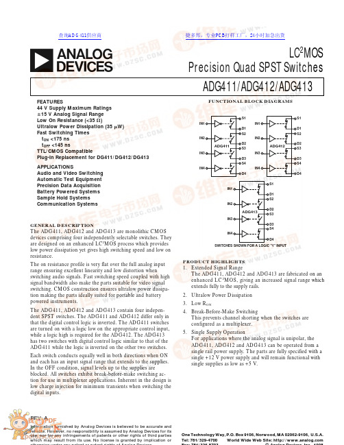
FUNCTIONAL BLOCK DIAGRAMSIN1IN2IN3IN4S1D1S2D2S3D3S4D4ADG411IN1IN2IN3IN4S1D1S2D2S3D3S4D4ADG412IN1IN2IN3IN4S1D1S2D2S3D3S4D4ADG413SWITCHES SHOWN FOR A LOGIC "1" INPUTREV.AInformation furnished by Analog Devices is believed to be accurate and reliable. However, no responsibility is assumed by Analog Devices for its use, nor for any infringements of patents or other rights of third parties which may result from its use. No license is granted by implication oraLC 2MOSPrecision Quad SPST Switches ADG411/ADG412/ADG413One Technology Way, P.O. Box 9106, Norwood, MA 02062-9106, U.S.A.Tel: 781/329-4700World Wide Web Site: FEATURES44 V Supply Maximum Ratings ؎15 V Analog Signal Range Low On Resistance (<35 ⍀)Ultralow Power Dissipation (35 W)Fast Switching Times t ON <175 ns t OFF <145 nsTTL/CMOS CompatiblePlug-In Replacement for DG411/DG412/DG413APPLICATIONSAudio and Video Switching Automatic Test Equipment Precision Data Acquisition Battery Powered Systems Sample Hold Systems Communication SystemsPRODUCT HIGHLIGHTS1.Extended Signal RangeThe ADG411, ADG412 and ADG413 are fabricated on an enhanced LC 2MOS, giving an increased signal range which extends fully to the supply rails.2.Ultralow Power Dissipation 3.Low R ON4.Break-Before-Make SwitchingThis prevents channel shorting when the switches are configured as a multiplexer.5.Single Supply OperationFor applications where the analog signal is unipolar, the ADG411, ADG412 and ADG413 can be operated from a single rail power supply. The parts are fully specified with a single +12 V power supply and will remain functional with single supplies as low as +5 V.GENERAL DESCRIPTIONThe ADG411, ADG412 and ADG413 are monolithic CMOS devices comprising four independently selectable switches. They are designed on an enhanced LC 2MOS process which provides low power dissipation yet gives high switching speed and low on resistance.The on resistance profile is very flat over the full analog input range ensuring excellent linearity and low distortion whenswitching audio signals. Fast switching speed coupled with high signal bandwidth also make the parts suitable for video signal switching. CMOS construction ensures ultralow power dissipa-tion making the parts ideally suited for portable and battery powered instruments.The ADG411, ADG412 and ADG413 contain four indepen-dent SPST switches. The ADG411 and ADG412 differ only in that the digital control logic is inverted. The ADG411 switches are turned on with a logic low on the appropriate control input,while a logic high is required for the ADG412. The ADG413has two switches with digital control logic similar to that of the ADG411 while the logic is inverted on the other two switches.Each switch conducts equally well in both directions when ON and each has an input signal range that extends to the supplies.In the OFF condition, signal levels up to the supplies are blocked. All switches exhibit break-before-make switching ac-tion for use in multiplexer applications. Inherent in the design is low charge injection for minimum transients when switching the digital inputs.查询ADG411供应商捷多邦,专业PCB打样工厂,24小时加急出货ADG411/ADG412/ADG413–SPECIFICATIONS1Dual Supply(V DD = +15 V ؎ 10%, V SS = –15 V ؎ 10%, V L = +5 V ؎ 10%, GND = 0 V, unless otherwise noted)B Version T Version–40؇C to–55؇C toParameter+25؇C+85؇C+25؇C+125؇C Units Test Conditions/Comments ANALOG SWITCHAnalog Signal Range V DD to V SS V DD to V SS VR ON2525Ω typ V D = ±8.5 V, I S = –10 mA;35453545Ω max V DD = +13.5 V, V SS = –13.5 V LEAKAGE CURRENTS V DD = +16.5 V, V SS = –16.5 V Source OFF Leakage I S (OFF)±0.1±0.1nA typ V D = ±15.5 V, V S = ϯ15.5 V;±0.25±5±0.25±20nA max Test Circuit 2Drain OFF Leakage I D (OFF)±0.1±0.1nA typ V D = ±15.5 V, V S = ϯ15.5 V;±0.25±5±0.25±20nA max Test Circuit 2Channel ON Leakage I D, I S (ON)±0.1±0.1nA typ V D = V S = ±15.5 V;±0.4±10±0.4±40nA max Test Circuit 3DIGITAL INPUTSInput High Voltage, V INH 2.4 2.4V minInput Low Voltage, V INL0.80.8V maxInput CurrentI INL or I INH0.0050.005µA typ V IN = V INL or V INH±0.5±0.5µA maxDYNAMIC CHARACTERISTICS2t ON110110ns typ R L = 300 Ω, C L = 35 pF;175175ns max V S = ±10 V; Test Circuit 4t OFF100100ns typ R L = 300 Ω, C L = 35 pF;145145ns max V S = ±10 V; Test Circuit 4 Break-Before-Make Time Delay, t D2525ns typ R L = 300 Ω, C L = 35 pF;(ADG413 Only)V S1 = V S2 = +10 V;Test Circuit 5Charge Injection55pC typ V S = 0 V, R S = 0 Ω, C L = 10 nF;Test Circuit 6OFF Isolation6868dB typ R L = 50 Ω, C L = 5 pF, f = 1 MHz;Test Circuit 7Channel-to-Channel Crosstalk8585dB typ R L = 50 Ω, C L = 5 pF, f = 1 MHz;Test Circuit 8C S (OFF)99pF typ f = 1 MHzC D (OFF)99pF typ f = 1 MHzC D, C S (ON)3535pF typ f = 1 MHzPOWER REQUIREMENTS V DD = +16.5 V, V SS = –16.5 VDigital Inputs = 0 V or 5 VI DD0.00010.0001µA typ1515µA maxI SS0.00010.0001µA typ1515µA maxI L0.00010.0001µA typ1515µA maxNOTES1Temperature ranges are as follows: B Versions: –40°C to +85°C; T Versions: –55°C to +125°C.2Guaranteed by design, not subject to production test.Specifications subject to change without notice.Truth Table (ADG411/ADG412)ADG411 In ADG412 In Switch Condition 01ON10OFF ADG411/ADG412/ADG413Single SupplyB Version T Version–40؇C to–55؇C toParameter+25؇C+85؇C+25؇C+125؇C Units Test Conditions/Comments ANALOG SIGNAL RANGE0 V to V DD0 V to V DD VR ON4040Ω typ0 < V D = 8.5 V, I S = –10 mA;8010080100Ω max V DD = +10.8 VLEAKAGE CURRENTS V DD = +13.2 VSource OFF Leakage I S (OFF)±0.1±0.1nA typ V D = 12.2/1 V, V S = 1/12.2 V;±0.25±5±0.25±20nA max Test Circuit 2Drain OFF Leakage I D (OFF)±0.1±0.1nA typ V D = 12.2/1 V, V S = 1/12.2 V;±0.25±5±0.25±20nA max Test Circuit 2Channel ON Leakage I D, I S (ON)±0.1±0.1nA typ V D = V S = +12.2 V/+1 V;±0.4±10±0.4±40nA max Test Circuit 3DIGITAL INPUTSInput High Voltage, V INH 2.4 2.4V minInput Low Voltage, V INL0.80.8V maxInput CurrentI INL or I INH0.0050.005µA typ V IN = V INL or V INH±0.5±0.5µA maxDYNAMIC CHARACTERISTICS2t ON175175ns typ R L = 300 Ω, C L = 35 pF;250250ns max V S = +8 V; Test Circuit 4t OFF9595ns typ R L = 300 Ω, C L = 35 pF;125125ns max V S = +8 V; Test Circuit 4Break-Before-Make Time Delay, t D2525ns typ R L = 300 Ω, C L = 35 pF;(ADG413 Only)V S1 = V S2 = +10 V;Test Circuit 5Charge Injection2525pC typ V S = 0 V, R S = 0 Ω, C L = 10 nF;Test Circuit 6OFF Isolation6868dB typ R L = 50 Ω, C L = 5 pF, f = 1 MHz;Test Circuit 7Channel-to-Channel Crosstalk8585dB typ R L = 50 Ω, C L = 5 pF, f = 1 MHz;Test Circuit 8C S (OFF)99pF typ f = 1 MHzC D (OFF)99pF typ f = 1 MHzC D, C S (ON)3535pF typ f = 1 MHzPOWER REQUIREMENTS V DD = +13.2 VDigital Inputs = 0 V or 5 VI DD0.00010.0001µA typ1515µA maxI L0.00010.0001µA typ1515µA max V L = +5.25 VNOTES1Temperature ranges are as follows: B Versions: –40°C to +85°C; T Versions: –55°C to +125°C.2Guaranteed by design, not subject to production test.Specifications subject to change without notice.(V DD = +12 V ؎ 10%, V SS = 0 V, V L = +5 V ؎ 10%, GND = 0 V, unless otherwise noted)Truth Table (ADG413)Logic Switch 1, 4Switch 2, 30OFF ON1ON OFFADG411/ADG412/ADG413ORDERING GUIDEModellTemperature Range Package Option 2ADG411BN –40°C to +85°C N-16ADG411BR –40°C to +85°C R-16A ADG411TQ –55°C to +125°C Q-16ADG411BRU –40°C to +85°C RU-16ADG412BN –40°C to +85°C N-16ADG412BR –40°C to +85°C R-16A ADG412TQ –55°C to +125°C Q-16ADG413BN –40°C to +85°C N-16ADG413BR–40°C to +85°CR-16ANOTES 1To order MIL-STD-883, Class B processed parts, add /883B to T grade part numbers.2N = Plastic DIP; R = 0.15" Small Outline IC (SOIC); RU= Thin Shrink Small Outline (TSSOP); Q = Cerdip.ABSOLUTE MAXIMUM RATINGS 1(T A = +25°C unless otherwise noted)V DD to V SS . . . . . . . . . . . . . . . . . . . . . . . . . . . . . . . . . . . .+44 V V DD to GND . . . . . . . . . . . . . . . . . . . . . . . . . .–0.3 V to +25 V V SS to GND . . . . . . . . . . . . . . . . . . . . . . . . . . .+0.3 V to –25 V V L to GND . . . . . . . . . . . . . . . . . . . . . .–0.3 V to V DD + 0.3 V Analog, Digital Inputs 2 . . . . . . . . . . .V SS –2 V to V DD +2 V or30 mA, Whichever Occurs FirstContinuous Current, S or D . . . . . . . . . . . . . . . . . . . . .30 mA Peak Current, S or D . . . . . . . . . . . . . . . . . . . . . . . . . .100 mA (Pulsed at 1 ms, 10% Duty Cycle max)Operating Temperature RangeIndustrial (B Version) . . . . . . . . . . . . . . . . .–40°C to +85°C Extended (T Version) . . . . . . . . . . . . . . . .–55°C to +125°CStorage Temperature Range . . . . . . . . . . . . .–65°C to +150°C Junction Temperature . . . . . . . . . . . . . . . . . . . . . . . . .+150°C Cerdip Package, Power Dissipation . . . . . . . . . . . . . . .900 mW θJA Thermal Impedance . . . . . . . . . . . . . . . . . . . . . .76°C/W Lead Temperature, Soldering (10 sec) . . . . . . . . . . .+300°C Plastic Package, Power Dissipation . . . . . . . . . . . . . . .470 mW θJA Thermal Impedance . . . . . . . . . . . . . . . . . . . . .117°C/W Lead Temperature, Soldering (10 sec) . . . . . . . . . . .+260°C SOIC Package, Power Dissipation . . . . . . . . . . . . . . . .600 mW θJA Thermal Impedance . . . . . . . . . . . . . . . . . . . . . .77°C/W TSSOP Package, Power Dissipation . . . . . . . . . . . . . .450 mW θJA Thermal Impedance . . . . . . . . . . . . . . . . . . . . .115°C/W θJC Thermal Impedance . . . . . . . . . . . . . . . . . . . . . .35°C/W Lead Temperature, SolderingVapor Phase (60 sec) . . . . . . . . . . . . . . . . . . . . . .+215°C Infrared (15 sec) . . . . . . . . . . . . . . . . . . . . . . . . . .+220°CNOTES 1Stresses above those listed under Absolute Maximum Ratings may cause perma-nent damage to the device. This is a stress rating only; functional operation of the device at these or any other conditions above those listed in the operational sections of this specification is not implied. Exposure to absolute maximum rating conditions for extended periods may affect device reliability. Only one absolute maximum rating may be applied at any one time.2Overvoltages at IN, S or D will be clamped by internal diodes. Current should be limited to the maximum ratings given.TERMINOLOGYV DD Most positive power supply potential.V SSMost negative power supply potential in dual supplies. In single supply applications, it may be connected to GND.V L Logic power supply (+5 V).GND Ground (0 V) reference.S Source terminal. May be an input or output.D Drain terminal. May be an input or output.IN Logic control input.R ONOhmic resistance between D and S.I S (OFF)Source leakage current with the switch “OFF.”I D (OFF)Drain leakage current with the switch “OFF.”I D , I S (ON)Channel leakage current with the switch “ON.”V D (V S )Analog voltage on terminals D, S.C S (OFF)“OFF” switch source capacitance.C D (OFF)“OFF” switch drain capacitance.C D , C S (ON)“ON” switch capacitance.t ON Delay between applying the digital control input and the output switching on.t OFF Delay between applying the digital control input and the output switching off.t D“OFF” time or “ON” time measured between the 90% points of both switches, when switching from one address state to another.CrosstalkA measure of unwanted signal which is coupled through from one channel to another as a result of parasitic capacitance.Off Isolation A measure of unwanted signal coupling through an “OFF” switch.Charge A measure of the glitch impulse transferred Injectionfrom the digital input to the analog output during switching.PIN CONFIGURATION(DIP/SOIC)CAUTIONESD (electrostatic discharge) sensitive device. Electrostatic charges as high as 4000V readily accumulate on the human body and test equipment and can discharge without detection.Although the ADG411/ADG412/ADG413 feature proprietary ESD protection circuitry, permanent damage may occur on devices subjected to high energy electrostatic discharges. Therefore, proper ESD precautions are recommended to avoid performance degradation or loss of functionality.ADG411/ADG412/ADG413Typical Performance GraphsFigure 1.On Resistance as a Function of V D (V S ) Dual Supplies Figure 2.On Resistance as a Function of V D (V S ) for Different TemperaturesFigure 3.Leakage Currents as a Function of TemperatureFigure 4.On Resistance as a Function of V D (V S ) Single SupplyFigure 5.Supply Current vs. Input Switching FrequencyFigure 6.Leakage Currents as a Function of V D (V S )ADG411/ADG412/ADG413Figure 7.Off Isolation vs. Frequency Figure 8.Crosstalk vs. Frequency APPLICATIONFigure 9 illustrates a precise, fast, sample-and-hold circuit. An AD845 is used as the input buffer while the output operational amplifier is an AD711. During the track mode, SW1 is closed and the output V OUT follows the input signal V IN. In the hold mode, SW1 is opened and the signal is held by the hold capaci-tor C H.Due to switch and capacitor leakage, the voltage on the hold capacitor will decrease with time. The ADG411/ADG412/ADG413 minimizes this droop due to its low leakage specifica-tions. The droop rate is further minimized by the use of a poly-styrene hold capacitor. The droop rate for the circuit shown is typically 30 µV/µs.A second switch, SW2, which operates in parallel with SW1, is included in this circuit to reduce pedestal error. Since both switches will be at the same potential, they will have a differen-tial effect on the op amp AD711, which will minimize charge injection effects. Pedestal error is also reduced by the compensa-tion network R C and C C. This compensation network also re-duces the hold time glitch while optimizing the acquisition time. Using the illustrated op amps and component values, the pedes-tal error has a maximum value of 5 mV over the ±10 V input range. Both the acquisition and settling times are 850 ns.Figure 9.Fast, Accurate Sample-and-HoldADG411/ADG412/ADG413Test Circuit 1.On ResistanceTest Circuit 3.On LeakageTest CircuitsTest Circuit 2.Off LeakageTest Circuit 4.Switching TimesTest Circuit 5.Break-Before-Make Time DelayTest Circuit 6.Charge InjectionADG411/ADG412/ADG413C 1748a –3–2/98Test Circuit 8.Channel-to-Channel CrosstalkTest Circuit 7.Off Isolation P R I N T E D I N U .S .A .16-Lead Cerdip(Q-16)16-Lead Plastic DIP (Narrow)(N-16)MECHANICAL INFORMATIONDimensions are shown in inches and (mm).16-Lead SOIC (R-16A)16-Lead TSSOP(RU-16)。
S1132_中文规格书
精工电子有限公司
5
高纹波抑制率 S-1132系列
低压差型
中输出电流CMOS电压稳压器 Rev.4.0_00
绝对最大额定值
表5 项目 输入电压 输出电压 SOT-23-5 容许功耗 SOT-89-5 SNT-6A(H) 工作环境温度 保存温度 *1. 基板安装时 [安装基板] (1) 基板尺寸: (2) 名称: Topr Tstg PD 符号 VIN VON/OFF VOUT (除特殊注明以外: Ta=25°C) 绝对最大额定值 单位 V VSS−0.3 ∼ VSS+7 V VSS−0.3 ∼ VIN+0.3 V VSS−0.3 ∼ VIN+0.3 300(基板未安装时) mW 600*1 500(基板未安装时) 1000*1 500
*1. 请注意在输出大电流时的封装容许功耗。 *2. 详情请参阅“ 产品型号的构成”。
用途
• 电池供电设备的稳压电源 • 通信设备的稳压电源 • 家电产品的稳压电源 • 携带电话的稳压电源
封装
• SOT-23-5 • SOT-89-5 • SNT-6A(H)
精工电子有限公司
1
高纹波抑制率 S-1132系列 框图
S-1132
x
xx
−
xxxx
x
环保标记 U: 无铅 (Sn 100%)、无卤素 G: 无铅 (详情请向本公司营业部咨询) 封装简称和IC的包装规格*1 M5T1: SOT-23-5、卷带产品 U5T1: SOT-89-5、卷带产品 I6T2: SNT-6A(H)、卷带产品 输出电压 12 ~ 55 (例: 当输出电压为1.5 V时,表示为15) 产品类型*2 A: ON/OFF端子为负逻辑型 B: ON/OFF端子为正逻辑型 *1. *2. 请参阅卷带图。 请参阅工作说明“3. 开/关控制端子(ON/OFF 端子)”。
LN1134_c
■ 封装
z SOT-25
z USP-6B
■ 功能框图
图 1 LN1134 功能框图
上海南麟电子有限公司
1
■ 绝对最大额定值
150mA 低压差 CMOS 电压稳压器 LN-1134 系列
项目 输入电压 输出电压 容许功耗 工作温度 保存温度
符号 VIN VON/OFF VOUT
PD
Topr Tstg
绝对最大额定值
VSS-0.3~VSS+8 VSS-0.3~VIN+0.3 VSS-0.3~VIN+0.3
SOT-25
250
USP-6B
100
-40~+85
-40~+125
单位 V
mW °C
注意 绝对最大额定值是指无论在任何条件下都不能超过的额定值。万一超过此额定值,有可能造成产品 劣化等物理性损伤。
6
④代表输出电压的整数位 例如:3 代表 3.x,5 代表 5.x;
⑤代表输出电压的小数
符号 0 1 2 3 4 5 6 7 8 9
电压(V) X.0 X.1 X.2 X.3 X.4 X.5 X.6 X.7 X.8 X.9
产品名 LN1134xx0xDx LN1134xx1xDx LN1134xx2xDx LN1134xx3xDx LN1134xx4xDx LN1134xx5xDx LN1134xx6xDx LN1134xx7xDx LN1134xx8xDx LN1134xx9xDx
不超过输出晶体管的电流容量,内置了过载电流保护电路、短路保护电路。因采用SOT-25,USP-6B
等小型封装,故可高密度安装。
■ 产品特点
可选择输出电压
可以在 1.5~5.0V 的范围内选择,步进为 0.1 V
高耐压低压差微功耗LDO
型号
输出电压(注)
MD7130H MD7133H MD7136H MD7141H MD7144H MD7150H
3.0V 3.3V 3.6V 4.1V 4.4V 5.0V
MD71XXH 系列是使用 CMOS 技术开发的低压差,低功耗电 流高精度降压稳压电路。由于内置有低通态电阻晶体管,因 而输入输出压差低。最高工作电压可达 32V,适合需要较高 耐压的应用电路。
-Vout=0V
(除特殊注明以外:Ta=25℃)
最小 典型
值
值
最大 值
单位
测定 电路
3.201 3.3 3.399 V
1
25
30
mA
1
40
60
mV
0.05 0.2 %/V
60
100
mV
1
±50
±100
ppm/ ℃
1.2
5
uA
2
32
V
1
30
mA
3
MD71XXH 系列(MD7136H,输出电压+3.6V)
高耐压低压差微功耗 LDO CMOS 电压稳压电路
MD71XXH 系列 30mA
■ 特性: ■ 特性:
·输出电压精度高。 ·输入输出压差低。 ·超低功耗电流。 ·低输出电压温漂 ·输入耐压。 ·输出短路保护 ■ 用途: ·使用电池供电设备的稳压电源 ·通信设备的稳压电源 ·家电玩具的稳压电源 ·移动电话用的稳压电源 ·便携式医用仪器稳压电源 ■ 产品选型
7130H 7133H 7136H 7141H 7144H 7150H
打印 MARK SOT-23-3L
130H 133H 136H 5-40H
144H 150H
稳压器F1117-3.3V
DF1117
1A 低压差稳压器
No: TDSPEC2002C Date:2002.08
上海大缔微电子有限公司
DF1117 1A 低压差稳压器
概述
DF1117 系列稳压器可提供1A直流输出,它可运行在输入输出相差1V的环境下。在最 大输出电流时,电压差设计可提供最大为1.3V,且它随着输出电流的减小而减小。芯片焊接 校准为参考电压的1%。这种限流起到平衡的作用,调整器和电源电路使超负载最小化。
1.1 1.3
V
900 1,100 1,500 mA
5
10 mA
5
10 mA
60
75
dB
60
72
dB
60
72
dB
60
68
dB
0.008 0.04 %W
55
µA
120 µA
0.2
5
µA
0.5
%
0.3
1
%
DF1117
上海大缔微电子有限公司 1A 低压差稳压器
参数
型号
测试条件
最小 标准 最大 单位
RMS输出噪音 (输出电压百分比 )
应用范围
高效率线性标准器 快速整流校准器 5V 到3.3V 的线性校准器 电池充电器 现行小型计算机系统接口终端 笔记本的电源设备
电池动力仪器
订购须知
封装类型
TO-252 DF1117-ADJ DF1117-1.5 DF1117-1.8 DF1117-2.5 DF1117-2.85 DF1117-3.3 DF1117-5.0 *附厂家地址
10mA≤ IOUT ≤ 1A,
1.5V≤ (VIN - VOUT) ≤ 12V
- 1、下载文档前请自行甄别文档内容的完整性,平台不提供额外的编辑、内容补充、找答案等附加服务。
- 2、"仅部分预览"的文档,不可在线预览部分如存在完整性等问题,可反馈申请退款(可完整预览的文档不适用该条件!)。
- 3、如文档侵犯您的权益,请联系客服反馈,我们会尽快为您处理(人工客服工作时间:9:00-18:30)。
Features
• Output voltage :
2.0 V to 12.0 V, selectable in 0.1 V step
• Low equivalent series resistance capacitor : Ceramic capacitor of 0.1 μF or more can be used as the I/O capacitor.
S-1142 Series
© Seiko Instruments Inc., 2009-2010
HIGH-WITHSTAND VOLTAGE LOW CURRENT CONSUMPTION LOW DROPOUT CMOS VOLTAGE REGULATOR
Rev.2.0_00
Remark 1. Please contact our sales office for products with an output voltage other than those listed above or type A products.
2. Please select products of environmental code = U for Sn 100%, halogen-free products.
• Output current :
During shutdown: 0.1 μA typ., 1.0 μA max. (Tj = −40°C to +105°C) 200 mA (at VIN ≥ VOUT(S) + 2.0 V)*1
• Built-in overcurrent protector :
HSOP-6 (+85°C supported) S-1142B20I-E6T1U S-1142B25I-E6T1U S-1142B27I-E6T1U S-1142B28I-E6T1U S-1142B2JI-E6T1U S-1142B30I-E6T1U S-1142B32I-E6T1U S-1142B33I-E6T1U S-1142B35I-E6T1U S-1142B37I-E6T1U S-1142B40I-E6T1U S-1142B50I-E6T1U S-1142B80I-E6T1U
• Input voltage :
3.0 V to 50 V
• High-accuracy output voltage :
±1.0% (at Tj = +25°C), ±3.0% (Tj = −40°C to +105°C)
• Low current consumption :
During operation: 4.0 μA typ., 9.0 μA max. (Tj = −40°C to +105°C)
12 3 Figure 2
Table 2
Pin No. 1 2 3 4 5 6
Symbol VOUT VSS ON/OFF NC*1 VSS
Seiko Instruments Inc.
1
HIGH-WITHSTAND VOLTAGE LOW CURRENT CONSUMPTION LOW DROPOUT CMOS VOLTAGE REGULATOR S-1142 Series
Block Diagram
Rev.2.0_00
VIN ON/OFF
Package
• HSOP-6
Caution Before using this product in medical equipment or automobile equipment including car audio, keyless entry and engine control unit, contact to SII is indispensable.
Applications
• Constant-voltage power supply for electrical applications for vehicle interiors (S-1142xxxH only) • Constant-voltage power supplies for home electric appliances
4
Seiko Instruments Inc.
Rev.2.0_00
HIGH-WITHSTAND VOLTAGE LOW CURRENT CONSUMPTION LOW DROPOUT CMOS VOLTAGE REGULATOR S-1142 Series
Pin Configuration
HSOP-6 Top view 65 4
*1
Overcurrent protector
Thermal shutdown circuit
+ ON/OFF circuit
−
VOUT
Reference voltage circuit
VSS
*1. Parasitic diode
Figure 1
2
Seiko Instruments Inc.
Rev.2.0_00
1. Product Name
S-1142 x xx x - xxxx U
Environmental code U : Lead-free (Sn 100%), halogen-free
Package abbreviation and IC packing specifications*1 E6T1 : HSOP-6, Tape (S-1142xxxI only) E6T2 : HSOP-6, Tape (S-1142xxxH only)
HSOP-6 (+105°C supported) S-1142B20H-E6T2U S-1142B25H-E6T2U S-1142B27H-E6T2U S-1142B28H-E6T2U S-1142B2JH-E6T2U S-1142B30H-E6T2U S-1142B32H-E6T2U S-1142B33H-E6T2U S-1142B35H-E6T2U S-1142B37H-E6T2U S-1142B40H-E6T2U S-1142B50H-E6T2U S-1142B80H-E6T2U
The S-1142 Series, developed based on high-withstand voltage CMOS process, is a positive voltage regulator with a high-withstand voltage, low current consumption, and high output voltage accuracy. The S-1142 Series operates at a high maximum operating voltage of 50 V and a low current consumption of 4.0 μA (typ.). In addition to a built-in low on-resistance transistor which provides a very small dropout voltage and a large output current, this voltage regulator also has a built-in power-off circuit. An overcurrent protector prevents the load current from exceeding the capacitance of the output transistor. A built-in thermal shutdown circuit prevents damage caused by heat. A high heat radiation HSOP-6 package enables high-density mounting.
limisistor
• Operation temperature range :
−40°C to +105°C (S-1142xxxH only)
• Built-in thermal shutdown circuit :
prevents damage caused by heat
Product type*2 A : ON/OFF pin negative logic B : ON/OFF pin positive logic
*1. Refer to the tape specifications. *2. Refer to “3. Power-off pin (ON/OFF pin)” in “ Operation”.
2. Package
Package Name HSOP-6
Package FH006-A-P-SD
Drawing Code
Tape
Reel
FH006-A-C-SD
FH006-A-R-SD
Land FH006-A-L-SD
Seiko Instruments Inc.
3
HIGH-WITHSTAND VOLTAGE LOW CURRENT CONSUMPTION LOW DROPOUT CMOS VOLTAGE REGULATOR S-1142 Series
• Built-in power on/off circuit : • Lead-free, Sn 100%, halogen-free*2
longer battery life
*1. Attention should be paid to the power dissipation of the package when the output current is large. *2. Refer to “ Product Name Structure” for details.