WD-4000控制器说明书
WP4000变频功率分析仪说明书
声明
我们非常认真的整理此手册,但我们对本手册的内容不保证完全正确。因为我们的产 品一直在持续的改良及更新,故我方保留随时修改本手册的内容而不另行通知的权利。同 时我们对不正确使用本手册所包含内容而导致的直接、间接、有意、无意的损坏及隐患概 不负责。
安全操作知识
严禁在带电的情况去触碰变频功率传感器和 DT 数字变 送器, 严禁在带电的情况将变频功率传感器和 DT 数字 变送器直接与任何导电体直接接触。
目录
目录 ................................................................................................................................... I 1 产品介绍 ....................................................................................................................... 2 1.1 产品特点 ................................................................................................................. 2 1.2 系统构成 ................................................................................................................. 4 1.3 工作原理 ................................................................................................................. 5 1.4 系统精度 ................................................................................................................. 6 2 WP4000 变频功率分析仪 .............................................................................................. 8 2.1 变频功率分析仪构成 ............................................................................................... 8 2.2 变频功率分析仪安装 ............................................................................................. 10 2.3 分析仪安装示意图(台式、嵌入式) ................................................................... 11 2.4 WP4000 变频功率分析仪操作与使用 .................................................................... 13 2.5 通讯协议(适用 V3.01 01-06 以上) ................................................................... 27 3 SP 系列变频功率传感器 .............................................................................................. 36 3.1 主要特点 ............................................................................................................... 36 3.2 技术指标 ............................................................................................................... 37 3.3 传感器的安装 ........................................................................................................ 38 3.4 传感器外形与尺寸 ................................................................................................ 47 3.5 接线说明 .....................................................................................错误!未定义书签。 3.6 选型指南 ............................................................................................................... 60 3.7 其他 ...................................................................................................................... 62 4 DT 数字变送器 ............................................................................................................. 63 4.1 产品特点 ............................................................................................................... 63 4.2 技术指标 ............................................................................................................... 63
WD-4000控制器说明书

WD-4000变频恒压供水电脑控制器使用手册目录系统概述 (2)主要性能指标 (2)安装尺寸和接线端子说明 (3)操作面板指示及参数设定说明 (4)参数列表及参数出厂默认值 (6)恢复系统参数出厂值 (6)系统参数功能详细说明 (9)故障显示代码说明 (16)外部输入信号端子说明 (16)系统当前时间的调整 (16)手动临时开机的调整 (16)外部输出端子与部分变频器端子的连接表 (17)控制器与压力变送器的连接 (18)RS485远程通讯接口 (18)一、系统概述WD-4000系列微电脑变频供水/补水控制器是专为变频恒压供水系统和锅炉及换热系统补水而设计的电脑控制器,可与各种品牌的变频器配套使用。
具有压力控制精度高、压力稳定、第二消防压力(动压)设定、系统超压泄水自动控制、设定参数密码锁定等多项功能。
二、主要性能指标1.可编程设定多种泵工作方式,最多可拖4台泵循环启动;2.可选配的RS485远程通讯接口,标准组态软件支持远程通讯;3.参数调整和设定具有密码锁定及保护功能;4.采用人工智能模糊控制算法,设定参数少,控制精度高,内带看门狗电路,采用数字滤波及多项抗干扰措施,防止软件跑飞;5.可接无源远传压力表、有源电压及电流型压力变送器;6. D/A输出控制频率电压为DC 0-10V, 也可设定为DC 0-5V;7.具有压力传感器零点和满度补偿功能;8.具有定时自动倒泵功能;9.具有第二压力(消防压力)设定和控制功能;10.具有缺水自动检测保护功能和外部输入停机保护功能;11.系统补水控制时,具有超压自动泄水控制功能;12.具有供水附属小泵控制功能,可设定小泵变频或工频模式;13.具有可选的定时自动开、关机控制功能;14.具有小流量水泵睡眠控制功能;15.具有手操器功能,可手动调节输出电压来控制变频器的频率;16.可代替电接点压力表进行上、下限压力控制;17.具有分时分压供水控制功能,最多有六段时间控制;三、安装尺寸和接线端子说明1.控制器外形尺寸: 160mm×80mm×90mm2.控制柜面板开口尺寸151mm×75mm,面板卡入式安装。
4000系列(4+1)防盗门系统技术手册

CONTENTSPAGE Manual introduction 4 System introduction 4 System components 4 – 13 Codelock programming instructions 15 – 16 Accessories 13 – 14 Installation 14 Cable size guide 17 Testing the system 17 Panel care 17 Accessories connection guide 17 – 18 Single entrance single button audio wiring diagram 19 Single or multiple entrance, multiple button audio wiring diagram20 Single entrance video system wiring diagram 21 Multiple entrance video system wiring diagram 22 Troubleshooting guide 23The information in this manual is intended as an installation and commissioning guide for the vandal resistant 4000 Series door entry systems. This manual should be read carefully before the installation commences. Any damage caused to the equipment due to faulty installations where the information in this manual has not been followed is not the responsibility of Videx Security Ltd.VIDEX run free training courses for engineers who are not familiar with the Videx product range. Technical help is also available on 0191 224 3174 during office hours or via e-mail ***********************.This kit will enable a caller at an entrance point to signal an occupant in the dwelling by pressing a call button which will send an electronic call tone to an audio telephone. A Yellow ‘SPEAK’ LED will indicate the call has been answered and a two way conversation can take place, the occupant can release an electric lock release by pressing a button on the telephone base unit. The output for the lock is a dry contact relay allowing any type of lock can be used with an appropriate PSU. If this system is to be used with a gate, the dry contact output can be used to trigger the gate control board. DDA features such as a ‘SPEAK’ LED, ‘DOOR OPEN’ LED and reassurance tones are standard on this system. The system is available modular and non-modular. The modular system allows a door panel to be assembled from a range of modules including amplifiers, button modules, camera modules and access control modules. The modules are then assembled into the 4000 Series frames using the brackets and screws supplied.The system comprises of door panels, telephones/videophones and power supplies. Relays will also be used on multiple door video systems but there are no switches required for multiple door audio systems as was the case with the older systems. The door panel may be made up of several parts including modules and a surface or flush frame. These modules are easily assembled into the frames using the brackets and screws supplied with each module. The order in which the modules fit into the frames is down to customer taste but we would suggest keeping the amplifier module as far from the microphone holder as possible to avoid Larsen affect.The vandal resistant door panel will consist of an amplifier, buttons, frame/back box and optional items such as camera and access control features (Codelock, proximity etc). Frame sizes are available for 1, 2, 4, 6 and 9 modules in both surface and flush fitting configurations. Call buttons can be engraved to suite the apartment numbers.Speech volume adjustments are carried out at the door panel using a small trimmer driver. CAMERA (Art.VR4KCMM – Mono & Art.VR4KCMC - Colour)The camera module is available in both mono and colour and can be set for either coax installations or non-coax installations. A tilt adjustment is available on the rear of the Connection FunctionNOTE: ANY 1A 13.8Vdc PSU can be used with this amplifier as an alternative to the 520M.20Vdc 800mA continuous 1A surge PSU and is used to power the videophones and camera on video systems and can also be used as a booster supply or when more than two videophones are required in an apartment. This power supply only has an output when either a 0V is applied to –C or when a voltage is applied to Connection Function5 5Art.3312DIP SWITCH SETTINGSThe Art.3312 (3412 for colour) includes a lock release push button, camera recall button and three dry contact push to make spare push buttons for other services. Coax and non-coax video can be used by setting the relevant dip-switches. An Art.3980 back plate is required with this videophone. CONNECTIONS:-Terminal Signal Function1 +12V Out +12V out to power video splitter2 TV1 Camera recall (● Button)3 TV2 Spare button (●● Button)4 1 +20V power input5 2 Door release command6 3 Transmit speech to door panel7 4 Receive speech from door panel8 5 Speech Ground9 6 Video power ground 107 Local call tone input11 V/V1 Coax centre core or balance video –sync (V1) 12 M/V2 Coax Screen or balanced video +sync (V2)13R Speech common for intercommunicating systems 14C Call tone input 15- Speech ground for intercommunicating systems 16T Common of spare buttons17 1T Spare button 18 2T Spare button 9 + Coax Or 11 coresThe Art.3313 (3413 for colour) includes a lock release push button and two dry contact push to make spare push buttons for other services. An Art.3980 back plate is required with this videophone. CONNECTIONS:- Terminal Signal Function 1 +12V OUT +12V out to power video splitter 2 TV1 Camera recall (● Button)3TV2 Camera recall or switch to terminal 16 (Dip switch dependant) (●● Button) 41 +20V power input 52 Door release command 63 Transmit speech to door panel7 4 Receive speech from door panel 8 6 0V (Ground) 9 5 Not used107 Local call tone input 11 V/V1 Coaxcentre core or non-coax sync- (V1) 12M/V2 Coax Screen or non-coax Sync+ (V2)13 D Switched +12 for door open LED 14C Select input to switch on videophone15 C1 Call tone input 16 T Common of spare buttons ●●, ● and S171T Spare button (S button) 18+12V IN +12V to power videophone privacy DIP SWITCH SETTINGS 8 Way dip switch (Switches 1 – 5) Mute Duration timeTime 1 2 3 4 5 15 Minutes ON OFF OFF OFF OFF 30 Minutes OFF ON OFF OFF OFF 2 Hours OFF OFF ON OFF OFF 4 Hours OFF OFF OFF ON OFF 8 Hours OFF OFF OFF OFF ON 3 Way Dip Switch VIDEO MODE continued Switch 1 2 3 Coax OFF OFF OFF Non-Coax ON ON ON8 Way dip switch (Switch 6) Mute LED Switch 6 Fixed OFF Flashing ON 8 Way dip switch (Switches 7 & 8) °° Button Operation Switch 7 8 Camera recall ON OFF Dry contact OFF ON 4 Way Dip Switch (Switches 1 & 2) S Button Operation Switch 1 2 Camera recall ON OFF Dry contact OFF ON 4 Way Dip Switch (Switches 3 & 4) VIDEO MODE Switch 3 4 Coax ON ON Non-Coax OFF OFF10 + CoaxOr12 coresCABLE SIZE GUIDESuitable cables for this system are CW1308 and YY cable (Other similar cables are also suitable) Care should be taken to avoid excessive voltage drop. Follow the guide lines below.Connections from door panel to telephones/videophones. Connections 50m 100m 200m 300m 400mPower0.35mm² 0. 5mm² 0.75mm² 1.00mm² 1.5mm² All Others0.25mm² 0.35mm² 0.5mm² 0.75mm² 1.0mm² Maximum acceptable resistance for power terminals 5Ω, all others 10ΩConnections for power supply output to door panel and lock release connections. Theseconnections are shown heavily outlined on the wiring diagram.50m 100mConnections0.5mm² 0.75mm² The power supply should be located as close to the door panel as possible for best performance.Maximum acceptable resistance for above cables 3Ω- Check all the connections have been made correctly and dip-switches have been set and then power up the system.- Call the apartments. Check for call to all apartments, speech in both directions and lock release and correct operation of the SPEAK & DOOR OPEN LED’s.- If the volume of speech needs to be adjusted, this can be done by adjusting the presets on the rear of the amplifier at the door panel.The door panel is manufactured from 12 Gauge 304 grade stainless steel. It is important that the facia is cleaned on regular occasions to prevent dirt build up and tarnishing of the metal. A general household metal polish can be used but care should be taken to follow the grain of the metal when polishing and also avoid any polish build up around the call button which may prevent the button from operating correctly.ES/1 Extension Strobe512A Extension sounderAdding the 4800 codelock to a panelSYMPTOM TESTNo speech from the door panel to the telephone.Check terminal 2 on the amplifier for continuity toterminal 2 on the telephone.Check the voltage drops to approx. 1Vdc after the handset is lifted. (If not try another telephone)If all else fails try another amplifier at the door stationNo speech from the telephone to the door panel.Check terminal 1 on the door panel amplifier forcontinuity back to terminal 1 on the telephone.Check the voltage drops to approx. 4Vdc after the handset is lifted. (If not try another telephone)If all else fails try another amplifier at the door stationNo speech in either directionCheck the 315mA fuse in the power supplyCheck for 12Vdc across terminals + & - on the door panel amplifier. This should be there all the time and comes directly from the PSU.Lock will not operate from telephoneCheck terminal 5 on the telephone. This terminal shorts to terminal 3 of the telephone when pressed (Becomes 0V) and sends a 0V to terminal 5 on the VX136 amplifier at the door panel which in turn triggers the relayCheck the relay on the VX136 is energising. Use a continuity meter to check the switching.Nothing happens when call button is pressedCheck the common of the button is connected to Ton the VX136Check continuity from the other side of the call button to terminal 4 on the handsetHum on the speech linesEnsure all intercom cables do not run close to higher voltage cablesTry another amplifier at the door panel.Rolling or poor video pictureCheck camera jumper setting is set correctly Check end of line resistors are fitted on last 316video splitter (Non-coax) or end of line resistors plus termination resistors on any unused outputs of the 894 video splitter (Coax).Check dip-switches are set correctly on videophone On multiple door systems, check that only onecamera is being switched on at a time. (When camera is switched on it will have 20Vdc across +&-Camera recall does not workCheck terminal TV1 (● button) wire for continuity to T of relevant door panel.On multiple door systems, lifting the handset causes feedback or speech from all doors at the same time.Dip switch 4 of the amplifier is switched on. This switch can only be on, for one door systems.Remember to power down after making the change.Northern OfficeVidex Security LtdUnit 4-7 Chillingham Ind. Est. Newcastle Upon TyneNE6 2XXTEL 0870 300 1240FAX 0191 224 5678 Southern Office1 OspreyTrinity ParkTrinity WayLondonE4 8TDFAX 0208 523 5825 TECHNICAL SUPPORT***********************TEL 0191 224 3174FAX 0191 224 4938。
L4000 智能控制器使用说明

L-4000智能控制器使用说明L4000智能控制器基本参数工作电压:220V外型尺寸:390*235*80 (H*W*D)最大负载:6000W单路负载:可调灯光1500W 开关灯光3000W功能简介L-4000灯光/空调智能控制器是专为KTV设计的一款具备灯光亮度调节、中央空调控制、可编程的智能型灯光/空调控制器。
1、设有6路大功率可调光及4路大功率继电器,满足各种灯光应用的需求2、可直接通过串口与机顶盒或电脑连接3、可直接连接灯光控板,脱离点歌系统及中控盒独立运行4、可对任一模式下的灯光状态进行编程,实现任意灯光搭配5、灯光控制器上可直接按键操作选择灯光模式及调节灯光亮度6、灯光亮度均衡,通过在不同模式下设置不同的亮度,实现场景效果切换,减少了灯光的开关次数,延长灯光使用寿命7、可外接遥控器对灯光进行遥控控制(选配)8、中央空调智能控制,配合点歌系统可实现远程开关空调9、配盒空调墙板通过温度探测,可智能控制风机及阀门的开关,减少能源浪费10、设有2组空调控制11、根据室温与设定温的比对,自动调节风速12、采用串口光电隔离技术,避免设备间的互相干扰灯光控制的设置一、灯光模式对应组的编程先关闭灯光控制器电源,按住设置及确认键不放,打开电源,等待约1秒,灯光控制器显示01并闪烁,表示01组,按△或▽键选择所要编程的组。
1、选择需要编程的组按△或▽键选择需要编程的组,按确认键进入该组编程设置;2、设置该组对各路灯光的控制状态数码管显示J1,对应指示灯指示出该模式下灯光的控制状态,亮表示控制,闪烁表示不控制,不亮表示强制关。
按▽键选择要设置的灯光,J1-JA表示灯光控制器的10路,按设置键进行设置,按确认键进入下一步设置;3、设置组的开关模式显示H1表示固定模式,显示H0表示开关模式(固定模式:例如,当按K歌时1、2、3路亮,再次按K歌时还是1、2、3路亮;开关模式:例如,当按K歌时1、2、3路亮,再次按K歌时1、2、3路灭),按设置键进行选择,按确认键进入下一步设置;4、设置组的亮度继承方式显示L1表示固定亮度,显示L0表示继承亮度(固定亮度,例如:进入K歌模式后,将其亮度由60调到80,第二次进入K歌模式时它的默认亮度还原为60;继承亮度,例如:进入K歌模式后,将其亮度由60调到80,第二次进入K歌模式时它的默认亮度为80)。
Omega CN4000系列温度控制器用户指南说明书

e-mail:**************For latest product manuals: CN4000 SERIESTemperature ControllersShop online at User’s G ui d e***********************Servicing North America:U.S.A. Omega Engineering, Inc.Headquarters: Toll-Free: 1-800-826-6342 (USA & Canada only)Customer Service: 1-800-622-2378 (USA & Canada only)Engineering Service: 1-800-872-9436 (USA & Canada only)Tel: (203) 359-1660 Fax: (203) 359-7700e-mail:**************For Other Locations Visit /worldwideThe information contained in this document is believed to be correct, but OMEGA accepts no liability for any errors it contains, and reserves the right to alter specifications without notice.CONTENTSMODEL CONFIGURATION (2)SPECIFICATIONS (3)PARAMETER AND SETTING (4)SYMBOL DESCRIPTIONS (7)INSTRUMENT INSTALLATION AND WIRING (8)DISPLAY AND OPERATIONS (9)OPERATION DESCRIPTION (10)MODEL CONFIGURATIONModel DescriptionCN4116 (*)-(**)-(***) 1/16 DIN controllerCN4216 (*)-(**)-(***) 1/16 DIN controller, with 0.0 decimalCN414 (*)-(**)-(***) 1/4 DIN controllerCN424 (*)-(**)-(***) 1/4 DIN controller, with 0.0 decimalCN418V (*)-(**)-(***) 1/8 DIN Vertical controllerCN428V (*)-(**)-(***) 1/8 DIN Vertical controller, with 0.0 decimalCN418H (*)-(**)-(***) 1/8 DIN Horizontal controllerCN428H (*)-(**)-(***) 1/8 DIN Horizontal controller, with 0.0 decimal*Specify controlling output code from Output Options table below**Specify alarm code from Alarm Options table below***Low voltage power supply option (-LV)Controlling Output OptionsOption Type CodeRelay -R1DC SSR driver -DC1Alarming Output OptionsOption Type CodeRelay -R2DC SSR driver -DC2Low voltage power supply optionHz50/60AC/DC,-LV 24VSPECIFICATIONSThermocouple RTD Input TypeK S R E J N PT100Range ℃/ ℉0 to1300 ℃32 to 2372 ℉0 to1700℃32 to 3092 ℉0 to1600℃32 to 2412 ℉0 to1000℃32 to 1832 ℉0 to1200℃32 to 2192 ℉0 to 1300℃32 to 2372 ℉-200 to 800℃-328 to 1472 ℉Accuracy:CN 4116/CN414/CN4180.3%FS ± 1℃/1.8°FCN4216/CN424/CN428 0.3%FS ± 0.1℃/0.18°FTemperature Display ResolutionCN 4116/CN414/CN4181℃/1℉CN4216/CN424/CN4280.1℃/0.1℉ON / OFF ControlControl MethodAI PID Control with Auto Tuning (AT)Relay Output (1A/250VAC)Output TypeVoltage Output for SSR(12V/30mA)Limit High / LowAlarm(Modularization) High deviation/Low deviation100~240VAC (-15%, +10%), or 24VDC Supply Voltage50 to 60HzPower Consumption ≦ 3WOperating EnvironmentsTemperature: -10 to +60℃ / 14 to 140℉Humidity: 0~90RH%Electromagnetic compatibility (EMC) IEC61000-4-4: ± 4KV/5KHz IEC61000-4-5: 4KVPARAMETER AND SETTINGField parameter table (Primary parameters)Code Description Remarks SettingRange DefaultHIAL High limit alarm Alarm on when PV>HIALalarm off when PV<HIAL- AHYS-999~+3000 3000LoAL Low limit alarm Alarm on when PV<LoAL;alarm off when PV>LoAL + AHYS-999~+3000 -999HdAL Deviation highalarmAlarm on when PV-SV>HdAL;alarm off when PV-SV<HdAL - AHYS-999~+3000 3000LdAL Deviation lowalarmAlarm on when PV-SV<LdAL;alarm off when PV-SV>LdAL + AHYS-999~+3000 -999Loc Parameter LockLocAutoTuningSVPrimaryParameterSecondaryParameter0 X1 X X2 X X X3 X X X X808: allow to modify data or execute ATX : not allow to modify data or execute AT0~255 0System parameter table (Secondary parameters)Scb Input Shift Parameter Scb is used to make input shift tocompensate the error produced by sensor or inputsignal itself.PV-after-compensation=PV-before-compensation + Scb.-199~+400FILt PV input filter The value of FILt will determine the ability offiltering noise.When a large value is set, the measurement inputis stabilized but the response speed is slow.Generally, if great interference exists, then youcan increase parameter “FILt” gradually to makemomentary fluctuation of measured value lessthan 2 to 5.When the meter of the instrument is beingexamined at laboratory, “FILt” should be set to 0or 1 to short the response time.0~40 1Fru Selection of powerfrequency andtemperature scale50C: 50Hz, ℃50F: 50Hz, ℉60C: 60Hz, ℃60F: 60Hz, ℉50C, 50F,60C, 60F50CSPL Low limit of SV -999~3000SPH Upper limit of SV -999~3000400SYMBOL DESCRIPTIONS Symbol DescriptionorAL Input specification setting is incorrectOrInput wiring is disconnected/ thermocouple problem OrShort circuitedHIAL High limit alarm LoAL Low limit alarm HdAL Deviation high alarm LdAL Deviation low alarm EErr IC Software error 8888 IC Software errorINSTRUMENT INSTALLATION AND WIRINGWiring graph for instruments with dimension 1/4 DIN; 1/8 DIN Vertical and HorizontalNote: The compensation wires for different kinds of thermocouple are different, and should be directly connect to the terminals. Connecting the common wire between the compensation wire and the t e r m i n a l s w i l l c a u s e m e a s u r e m e n t e r r o r.Wiring graph for 1/16 DIN dimension instruments :DISPLAY AND OPERATIONS①Upper display window, displays PV,parameter code, etc.②Lower display window, displays SV,parameter value, or alarm③Setup key, for accessing parametertable and conforming parametermodification.④Data shift key, and auto tuning.⑤Data decrease key⑥Data increase key⑦LED indicator. MAN, PRG, MIO,COM, OP2, AL2, AU1 and AU2Com indicators is non-applicable.OP1 and AL1 will indicate I/O operation of the corresponding module.Basic display status:When power on, the upper display window of the instrument shows the process value (PV), and the lower window shows the set-point (SV). This status is called basic display status.When the input signal is out of the measurable range (for example, the thermocouple or RTD circuit is break, or input specification sets wrong), the upper display window will alternately display “orAL” and the high limit or the low limit of PV, and the instrument will automatically stop output. If the lower display window alternately display “HIAL”, “LoAL”, “HdAL” or “LdAL”, it means high limit alarm, low limit alarm, deviation high alarm, and deviation low alarm happening.OPERATION DESCRIPTIONz Set Value Setting:In basal display status, if the parameter lock “Loc” isn't locked, we can set setpoint (SV) by pressing 、 or . Press key to decrease the value, key to increase the value, and key to move to the digit expected to modify. Keep pressing or , the speed of decreasing or inscreasingvalue get quick. The range of setpoint is between the parameter SPL and SPH.The default range is 0~400.z Parameter Setting:In basal display status, press and hold for about 2 seconds can accessField Parameter Table. Pressing can go to the next parameter; pressing 、 or can modify a parameter. Press and hold can return tothe preceding parameter. Press (don't release) and then press key simultaneously can escape from the parameter table. The instrument will escape auomatically from the parameter table if no key is pressed within 30 seconds. Setting Loc=808 and then press can access System Parameter Table.●AI artificial intelligence control and auto tuningWhen AI artificial intelligence control method is chosen (CtrL=APId), the PID parameters can be obtained by running auto-tuning. In basal display status,press for 2 seconds, the “At” parameter will appear. Press to changethe value of At from “oFF” to “on”, then press to active the auto-tuning process. During auto tuning, the instrument executes on-off control. After 2-3 times of on-off action, the instrument will obtain the optimal control parametervalue. If you want to escape from auto tuning status, press and hold thekey for about 2 seconds until the "At" parameter appear again. Change “At”from “on” to “oFF”, press to confirm, then the auto tuning process will be cancelled.Note 1: If the setpoint is different, the parameters obtained from auto-tuning are possible different. So you’d better set setpoint to an often-used value ormiddle value first, and then start auto-tuning. For the ovens with goodheat preservation, the setpoint can be set at the highest applicabletemperature. Depending on the system, the auto-tuning time can befrom several seconds to several hours.Note 2: Parameter Ctl (on-off differential, control hysteresis) has influence on the accuracy of auto-tuning. Generally, the smaller the value of Ctl, thehigher the precision of auto tuning. But Ctl parameter value should belarge enough to prevent the instrument from error action around setpointdue to the oscillation of input. Ctl is recommended to be 2.0.Note 3: The instrument has the function of self-learning. It is able to learn the process while working. The control effect at the first run after auto tuningis probably not perfect, but excellent control result will be obtained after aperiod of time because of self-learning.10OMEGA’s policy is to make running changes, not model changes, whenever an improvement is possible. T his affords our customers the latest in technology and engineering.OMEGA is a trademark of OMEGA ENGINEERING, INC.© Copyright 2018 OMEGA ENGINEERING, INC. All rights reserved. T his document may not be copied, photocopied, reproduced, translated, or reduced to any electronic medium or machine-readable form, in whole or in part, without the prior written consent of OMEGA ENGINEERING, INC.FOR WARRANTY RETURNS, please have the following information available BEFORE contacting OMEGA:1. P urchase Order number under which the product was PURCHASED,2. M odel and serial number of the product under warranty, and3. Repair instructions and/or specific problems relative to the product.FOR NON-WARRANTY REPAIRS, consult OMEGA for current repair charges. Have the following information available BEFORE contacting OMEGA:1. Purchase Order number to cover the COST of the repair,2. Model and serial number of the product, and 3. Repair instructions and/or specific problems relative to the product.RETURN REQUESTS/INQUIRIESDirect all warranty and repair requests/inquiries to the OMEGA Customer Service Department. BEFORE RET URNING ANY PRODUCT (S) T O OMEGA, PURCHASER MUST OBT AIN AN AUT HORIZED RET URN (AR) NUMBER FROM OMEGA’S CUST OMER SERVICE DEPART MENT (IN ORDER T O AVOID PROCESSING DELAYS). The assigned AR number should then be marked on the outside of the return package and on any correspondence.T he purchaser is responsible for shipping charges, freight, insurance and proper packaging to preventbreakage in transit.WARRANTY/DISCLAIMEROMEGA ENGINEERING, INC. warrants this unit to be free of defects in materials and workmanship for a period of 25 months from date of purchase. OMEGA’s WARRANTY adds an additional one (1) month grace period to the normal two (2) year product warranty to cover handling and shipping time. This ensures that OMEGA’s customers receive maximum coverage on each product.If the unit malfunctions, it must be returned to the factory for evaluation. OMEGA’s Customer Service Department will issue an Authorized Return (AR) number immediately upon phone or written request. Upon examination by OMEGA, if the unit is found to be defective, it will be repaired or replaced at no charge. OMEGA’s WARRANT Y does not apply to defects resulting from any action of the purchaser, including but not limited to mishandling, improper interfacing, operation outside of design limits, improper repair, or unauthorized modification. T his WARRANT Y is VOID if the unit shows evidence of having been tampered with or shows evidence of having been damaged as a result of excessive corrosion; or current, heat, moisture or vibration; improper specification; misapplication; misuse or other operating conditions outside of OMEGA’s control. Components in which wear is not warranted, include but are not limited to contact points, fuses, and triacs.OMEGA is pleased to offer suggestions on the use of its various products. However, OMEGA neither assumes responsibility for any omissions or errors nor assumes liability for any damages that result from the use of its products in accordance with information provided by OMEGA, either verbal or written. OMEGA warrants only that the parts manufactured by the company will be as specified and free of defects. OMEGA MAKES NO OTHER WARRANTIES OR REPRESENTATIONS OF ANY KIND WHATSOEVER, EXPRESSED OR IMPLIED, EXCEPT THAT OF TITLE, AND ALL IMPLIED W ARRANTIES INCLUDING ANY W ARRANTY OF MERCHANTABILITY AND FITNESS FOR A PARTICULAR PURPOSE ARE HEREBY DISCLAIMED. LIMITATION OF LIABILITY: The remedies of purchaser set forth herein are exclusive, and the total liability of OMEGA with respect to this order, whether based on contract, warranty, negligence, indemnification, strict liability or otherwise, shall not exceed the purchase price of the component upon which liability is based. In no event shall OMEGA be liable for consequential, incidental or special damages.CONDITIONS: Equipment sold by OMEGA is not intended to be used, nor shall it be used: (1) as a “Basic Component” under 10 CFR 21 (NRC), used in or with any nuclear installation or activity; or (2) in medical applications or used on humans. Should any Product(s) be used in or with any nuclear installation or activity, medical application, used on humans, or misused in any way, OMEGA assumes no responsibility as set forth in our basic WARRANT Y /DISCLAIMER language, and, additionally, purchaser will indemnify OMEGA and hold OMEGA harmless from any liability or damage whatsoever arising out of the use of theProduct(s) in such a manner.Where Do I Find Everything I Need forProcess Measurement and Control?OMEGA…Of Course!Shop online at TEMPERATUREM U Thermocouple, RTD & Thermistor Probes, Connectors,Panels & AssembliesM U Wire: Thermocouple, RTD & ThermistorM U Calibrators & Ice Point ReferencesM U Recorders, Controllers & Process MonitorsM U Infrared PyrometersPRESSURE, STRAIN AND FORCEM U Transducers & Strain GagesM U Load Cells & Pressure GagesM U Displacement TransducersM U Instrumentation & AccessoriesFLOW/LEVELM U Rotameters, Gas Mass Flowmeters & Flow ComputersM U Air Velocity IndicatorsM U Turbine/Paddlewheel SystemsM U Totalizers & Batch ControllerspH/CONDUCTIVITYM U pH Electrodes, Testers & AccessoriesM U Benchtop/Laboratory MetersM U Controllers, Calibrators, Simulators & PumpsM U Industrial pH & Conductivity EquipmentDATA ACQUISITIONM U Communications-Based Acquisition SystemsM U Data Logging SystemsM U Wireless Sensors, Transmitters, & ReceiversM U Signal ConditionersM U Data Acquisition SoftwareHEATERSM U Heating CableM U Cartridge & Strip HeatersM U Immersion & Band HeatersM U Flexible HeatersM U Laboratory HeatersENVIRONMENTALMONITORING AND CONTROLM U Metering & Control InstrumentationM U RefractometersM U Pumps & TubingM U Air, Soil & Water MonitorsM U Industrial Water & Wastewater TreatmentM U pH, Conductivity & Dissolved Oxygen InstrumentsM4545/0418。
DEC-1000和DEC-4000控制器操作说明书讲述
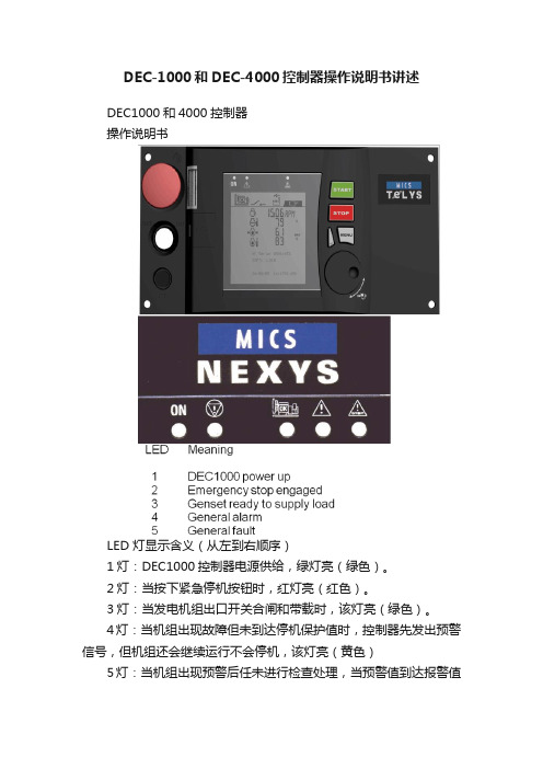
DEC-1000和DEC-4000控制器操作说明书讲述DEC1000和4000控制器操作说明书LED 灯显示含义(从左到右顺序)1灯:DEC1000控制器电源供给,绿灯亮(绿色)。
2灯:当按下紧急停机按钮时,红灯亮(红色)。
3灯:当发电机组出口开关合闸和带载时,该灯亮(绿色)。
4灯:当机组出现故障但未到达停机保护值时,控制器先发出预警信号,但机组还会继续运行不会停机,该灯亮(黄色)5灯:当机组出现预警后任未进行检查处理,当预警值到达报警值时,机组立即自动停止运行进行保护,该灯亮(红色)当机组运行时,RPM:显示机组运转的速度(1500转/分);同时显示机组运行时,充电机输出电压值:13.6V(直流)。
显示:控制器运行累计时间:23589小时;显示:发电机组输出电源频率:50Hz;显示:电池电压13.6V显示:柴油量在油箱的百分比值:37%显示:冷却液温度:85℃(水温)显示:机组运行中机油压力:3.2BAR以上为公制单位显示:柴油量在油箱的百分比值:37%显示:冷却液温度:85F(水温)显示:机组运行中机油压力:40-60PSI以上为英制单位显示:L1-L2相电压:404V;显示:L2-L3相电压:403V;显示:L3-L1相电压:401V显示:L1-N线电压233V;显示:L2-N线电压233V;显示:L3-N线电压232V.显示:L1相电流530A显示:L2相电流537A显示:L3线电流548A机侧启动1、将控制器上钥匙开关从左侧向右侧旋转,打开控制器电源,控制指示灯亮及液晶屏出现文字显示,控制器并读取程序;2、控制器绿色灯亮,说明机组无故障,准备就绪;3、按下“START”绿色按钮,机组立即进行预热10秒,10秒后机组立即启动,机组启动成功允许;4、读取机组允许参数:按下“左侧白色按钮”,每按一次,显示一组参数,其中参数包括:发动机转速、水温、机油压力、3相电压及频率、3相电流、电池电压等;5、按下“STOP”按钮,机组立即停止运转。
士林_温控器操作手册
ɛዚʧࠦEUӻΐeʃ̙ۨόછՓኜAX/AXONӻΐeᜊ᎖ኜSH/SS/SV/SEӻΐe ฆཥ໘ܓછՓኜSD/WTӻΐeᅰЗ္છ׳ᅂዚPHӻΐ
SUNX/ชኜʿཤ࢛ᅺႦዚeପ/ᜊ᎖ኜeCKD/٤Ꮐପۜecognex/ᅂ྅ชኜ(Checker)e Aiphone/ᅂ྅࿁ᑺዚeɧഷ/PLCeɛዚʧࠦeᜊ᎖ኜeУӻ୕
08122K185
微電腦溫度控制器 操作手冊
series series
目錄
1 注意事項...................................................................................................
22
9.2 Level2 (PID 層)
8.2.1
參數“顯示/隱藏”條件 .....................................................
23
8.2.2
參數說明 ......................................................................
14 更改輸入類型 : TC , RTD ................................................................................
40
15 更改輸入類型 : 類比電壓電流信號
15.1 硬體部分 .................................................................................................
DCAP-4000M说明书V1.0
第十四章DCAP-4000M主控单元1.概述DCAP-4000M主控单元是WDZ-400EX系列分布式微机综合保护测控装置联网时的核心单元,它一方面负责把WDZ-400EX系列单元的数据整理、汇总,再将这些信息上送后台机和DCS,完成遥信遥测;另一方面接收DCS或后台机下达的命令并转发给WDZ-400EX系列单元,完成对厂站内各开关设备的分合、电容器投切和主变分接头的升降,实现遥控和遥调。
同时它还配备了多个串行接口,以便与厂站内其它智能设备进行通讯。
它有如下主要特点:1.1.先进的嵌入式结构DCAP-4000M是以32位处理器80586为CPU的PC104作为单元的核心,它比普通单片机具有更强大的功能,同时具有体积小、集成度高、抗干扰能力强等优点。
PC104是专门用于工业和军事的工业PC标准,它具有普通PC机所具有的所有功能、能带显示器键盘、能带软驱硬驱、具有网络功能,同时它还具有特别的功能,如能带电子盘、体积很小、功耗较低、接插件非常牢靠等。
1.2.电子盘代替硬盘以前常用的PC机都具有一个共同的特点,即使用了硬盘,在家庭和办公室环境,它并不存在问题,但是在工业环境,它就变得不适应了,原因在于硬盘是高速旋转的机械结构,对振动、温度、湿度的要求比较高,而工业环境往往满足不了这些要求,致使PC机的硬盘经常出现故障。
电子盘就是为了这些原因而开发出来的,它是纯电气的,与其它大规模集成芯片一样,体积小,可靠性高,不易损坏。
1.3.强大的实时多任务操作系统DOS、WINDOWS等操作系统或是单任务或是分时的操作系统,其实时性均较差,还时常被稳定性、病毒所困扰,因些我们选用了实时多任务操作系统—-pSOS操作系统,它具有DOS、WINDOWS无法比拟的事件触发、任务调度功能,能确保工业环境中实时地反映突发事件并做出相应的处理。
1.4.丰富灵活的通讯功能单元共有12个RS232/422/485接口,其中两个提供光纤接口。
- 1、下载文档前请自行甄别文档内容的完整性,平台不提供额外的编辑、内容补充、找答案等附加服务。
- 2、"仅部分预览"的文档,不可在线预览部分如存在完整性等问题,可反馈申请退款(可完整预览的文档不适用该条件!)。
- 3、如文档侵犯您的权益,请联系客服反馈,我们会尽快为您处理(人工客服工作时间:9:00-18:30)。
WD-4000变频恒压供水电脑控制器使用手册目录系统概述 (2)主要性能指标 (2)安装尺寸和接线端子说明 (3)操作面板指示及参数设定说明 (4)参数列表及参数出厂默认值 (6)恢复系统参数出厂值 (6)系统参数功能详细说明 (9)故障显示代码说明 (16)外部输入信号端子说明 (16)系统当前时间的调整 (16)手动临时开机的调整 (16)外部输出端子与部分变频器端子的连接表 (17)控制器与压力变送器的连接 (18)RS485远程通讯接口 (18)1一、系统概述WD-4000系列微电脑变频供水/补水控制器是专为变频恒压供水系统和锅炉及换热系统补水而设计的电脑控制器,可与各种品牌的变频器配套使用。
具有压力控制精度高、压力稳定、第二消防压力(动压)设定、系统超压泄水自动控制、设定参数密码锁定等多项功能。
二、主要性能指标1.可编程设定多种泵工作方式,最多可拖4台泵循环启动;2.可选配的RS485远程通讯接口,标准组态软件支持远程通讯;3.参数调整和设定具有密码锁定及保护功能;4.采用人工智能模糊控制算法,设定参数少,控制精度高,内带看门狗电路,采用数字滤波及多项抗干扰措施,防止软件跑飞;5.可接无源远传压力表、有源电压及电流型压力变送器;6. D/A输出控制频率电压为DC 0-10V, 也可设定为DC 0-5V;7.具有压力传感器零点和满度补偿功能;8.具有定时自动倒泵功能;9.具有第二压力(消防压力)设定和控制功能;10.具有缺水自动检测保护功能和外部输入停机保护功能;11.系统补水控制时,具有超压自动泄水控制功能;12.具有供水附属小泵控制功能,可设定小泵变频或工频模式;13.具有可选的定时自动开、关机控制功能;14.具有小流量水泵睡眠控制功能;15.具有手操器功能,可手动调节输出电压来控制变频器的频率;16.可代替电接点压力表进行上、下限压力控制;17.具有分时分压供水控制功能,最多有六段时间控制;2三、安装尺寸和接线端子说明1.控制器外形尺寸: 160mm×80mm×90mm2.控制柜面板开口尺寸151mm×75mm,面板卡入式安装。
3.使用环境为:无水滴、蒸汽、腐蚀、易燃、灰尘及金属微粒的场所;4.使用环境温度:-20℃~50℃5.相对湿度:<95%;6.额定工作电压:AC220V±10%;7.控制器额定功耗:<=AC 5W;8.控制器接线端子输出容量:3A/ AC220V9.面板及接线端子说明:WD-4000型控制器面板示意图3WD-4000 型控制器端子接线图WD-4000型控制器接线端子说明:1------TX+ (RS485通讯接口+) 2------TX –(RS485通讯接口-)3------GND(信号地) 4------CM1(正转运行信号)5------FWD(正转运行信号) 6------ V+ (远传压力表高端+5V)7------IN(压力信号输入0-5V) 8------ GND(压力信号输入地)9------ DI2(缺水或停机信号输入) 10------DI1(第二压力信号输入端)11----- D/A (DC 0-10V输出) 12------ CM2(信号公共端2)13----- N(AC 220V零线) 14------L( AC 220V火线)15-----B1(1#变频运行触点) 16------B2(2#变频运行触点)17-----B3(3#变频运行触点) 18-----G1(1#工频运行触点)19-----G2(2#工频运行触点) 20-----G3(3#工频运行触点,泄压阀触点) 21-----B4(4#变频运行触点) 22-----G4(4#工频运行触点)23-----NC(空端子) 24-----NC(空端子)四、操作面板指示及参数设定说明面板及按键:PV窗口为测量值显示窗口,SV窗口为设定值显示窗口。
"S"键为参数4设定键,"▲"和"▼"为两个数字加减键,在参数设定状态,"M"键和""键为参数翻页键;在正常工作状态,""键为显示方式转换键,用来转换显示压力值和输出频率值;"●"键为工厂保留测试键.工作状态指示灯四个泵工作状态指示灯P1、P2、P3、P4表示四台泵,当指示灯为绿色时表示对应泵工作在变频方式,当指示灯为红色时,表示对应泵工作在工频方式。
当工作在第二压力(消防压力)状态时,AL指示灯显示绿色;当缺水(停机)端子接通(端子9和端子12接通)时或由于系统超压保护停机时,AL指示灯显示红色,同时控制器所有输出控制都停止,直到缺水(停机)状态解除(端子9和端子12断开)或系统压力恢复到设定值以下时,控制器重新开始工作。
参数的设定正常运行状态下,按住"S"键3秒,当显示窗口显示“时松开"S"键,进入参数设定状态,此时PV窗口显示参数项P00,SV窗口显示当前参数项的值。
"M"键或""键为参数项翻页键,用来显示不同的设定参数项;按"▲"或"▼"键改变当前参数项的值,改变后的值将被自动存储在仪表的存储器中。
当参数设定完成后,再按一下"S"键,仪表将返回正常工作状态下。
此时如果P00=18,按"▲"和"▼"键将直接改变当前的压力设定值(P01的设定值)。
在第二压力(消防)开关(端子10和端子12)闭合时,SV 窗口显示的是第二设定压力。
按"▲"和"▼"键将直接改变当前的第二设定压力值,第二压力也可以在P02中设定。
恢复系统参数出厂值断电状态下按住”S”键不松手,开机上电,当显示窗口显示“时松开"S"键,系统自动将所有参数恢复为出厂默认值。
5五、控制器参数列表及出厂默认值变频工频时间设定68六、控制器参数功能详细说明P00----参数修改密码。
当P00=18时,所有的参数和设定值均可修改,当P00<>18时,参数和设定值只能查看,不能修改。
P01----压力设定值,也称第一压力设定值或下限压力设定值。
当P03<>5时,P01就是系统当前的压力设定值,可在P01中设定或在运行状态直接在控制面板用"▲"和"▼"键直接设定。
当P03=5时,此值为下9限压力设定值。
P02----第二压力设定值,也称消防压力或动压设定值。
当外部输入信号端子DI1与CM2闭合超过2秒,则当前系统控制的设定压力值即变为P02的值,此时可在控制面板上直接用"▲"和"▼"键进行修改,修改后的数值直接存入P02参数项中。
当外部输入信号端子DI1与CM2断开后,控制面板上的设定压力值又重新变回P01的压力设定值。
P03----泵工作方式。
通过P03参数的改变,控制器可以控制单台或多台泵工作在不同的工作方式:P03=1,2,为一用一备工作模式,B1和B2互为备用泵。
当P12=1时,B1和B2按照P13中设定的时间定时相互轮流接通工作,G3为超压泄水触点。
P03=3,为一台变频泵加一台工频泵工作模式。
此时系统定义B1为变频泵,G1为工频泵。
当B1工作频率达到50Hz后,延时P05秒的时间,如果测量压力值仍然达不到系统设定值,则系统直接接通G1触点将工频泵投入系统运行。
如果系统出现超压,则将G1工频泵关掉,仍然靠调节B1泵的工作频率来稳定系统压力。
P03=4,是为锅炉补水或换热机组补水设计的工作模式。
此模式下系统定义B1为变频补水泵,G3为超压泄水电磁阀控制端子。
当测量压力>=(P01(或P02)+P20)时,G3接通,控制泄压电磁阀开启进行泄水。
当测量压力<=P01(或P02)时,G3断开,泄压停止。
P03=5, 为开关位式控制模式。
这种工作模式下,定义G1为1#工频补水泵,G2为2#工频补水泵,G3为超压泄水电磁阀控制端子。
此时SV压力设定值窗口显示的设定值为P21上限压力设定值。
此工作模式下,系统以P01为下限压力,P21为上限压力,代替电接点压力表进行压力控制。
当测量压力<=P01时,延时2秒,G1接通;经过P05时间后,如果压力仍然达不到P21,则G2接通;当测量压力>=P21时,G1断开;G1断开后;如果测量压力还高于P21,G2也断开;当测量压力>=(P21+P20)时,G3接通,控制泄压电磁阀开启进行泄水;当测量压力<=P21时,G3断开,停止泄压。
P03=6,为两泵循环软启动控制模式。
在此工作模式下,系统定义B1、B2为两台泵变频工作端子,G1、G2为两台泵工频工作端子。
此模式下系统上电工作时,先接通B1,启动1#泵变频工作。
当1#泵变频工作在50Hz时,延时P05秒,如果测量压力仍然达不到设定值,则将B1断开,接通G1,将1#泵由变频状态转换为工频工作状态,延时3秒,接通B2,启动2#泵进行变频工作。
当系统超压时,当2#泵变频工作在0Hz时,延时P06秒,系统仍然超压,将G1断开,切断1#泵工频,由2#泵进行变频调节保持系统的压力稳定。
当测量压力>=P01+P20时,G3接通,控制泄压阀泄水。
P03=7,为三泵循环软启动控制模式。
在此工作模式下,系统定义B1、B2、B3为三台泵变频工作端子,G1、G2、G3为三台泵工频工作端子。
此模式下系统上电工作时,先接通B1,启动1#泵变频工作。
当1#泵变频工作在50Hz时,延时P05秒,如果测量压力仍然达不到设定值,则将B1断开,接通G1,将1#泵由变频状态转换为工频工作状态,延时3秒,接通B2,启动2#泵进行变频工作。
当2#泵变频工作在50Hz时,延时P05秒,如果测量压力仍然达不到设定值,则将B2断开,接通G2,将2#泵由变频状态转换为工频工作状态,延时3秒,接通B3,启动3#泵进行变频工作。
当系统超压时,按先起先停的原则,逐个停掉工频泵,最后保留一台泵变频工作。
当系统欠压时,再按顺序逐个启动没投入工作的泵。
P03=8,为一台变频泵、两台工频泵的工作模式。
在此工作模式下,系统定义B1为变频工作泵,G1、G2为两台工频工作泵。
当B1工作频率达到50Hz后,延时P05秒的时间,如果测量压力仍然达不到系统设定值,则接通G1直接启动1#工频泵投入运行,当B1工作频率达再次到50Hz后,延时P05秒的时间,如果测量压力仍然达不到系统设定值,则接通G2启动2#工频泵投入运行,系统靠调节B1泵的工作频率来稳定压力。