P30L中文资料
Philips PFL6531 液晶电视用手册说明书
小心人身伤害、起火或电源线损坏! 切勿将电视机或任何物体放在电源线上。 电源插头作为断开装置,应当保持能方便地操作。 断开电源线时,应始终握住插头,而不能拉电缆。 雷雨天气来临之前,请断开电视机与电源插座及天线的连接。 在雷雨天气里,切勿触摸电视机、电源线或天线 的任何部分。 接入本设备的有线网络天线必须与保护接地隔离,否则可能会引起着火等危险!
小心伤害儿童! 请遵循以下注意事项,以避免因电视机掉落而导致儿童受伤:
切勿将电视机放在由可拉动的布或其它材料覆盖的表面上。 确保电视机的任何部分均位于表面边缘以内。
file:///D|/PHILIPS/TV/2013/Ebony/_Combine/e-Manual_20130325/PFL6531_465055/Important.html[2013/3/26 上午 09:50:05]
切勿让电视机与雨或水接触。 切勿将液体容器(例如花瓶)放置在电视机旁边或上面。 如果将液体洒到了电 视机表面或内部,请立即断开电视机的电源。 请与Philips 客户服务中心联系,对电视机进行检查后再行使用。 切勿将电视机、遥控器或电池放在明火或其它热源(包括直射的阳光)附近。为避免火焰蔓延,请始终使蜡烛 或其它明火远离电视机、遥控器和电池。
切勿向电视机上的通风槽或其它开口中插入任何物体。 旋转电视机时,请确保电源线不会绷紧。 电源线绷紧会使电源连接变松,进而产生火花。
小心短路或起火!
切勿将遥控器或电池暴露在雨中、水中或过热的环境中。 请避免电源插头产生拉力。 松动的电源插头可能产生火花或者导致起火。
TIM1414-30L中文资料
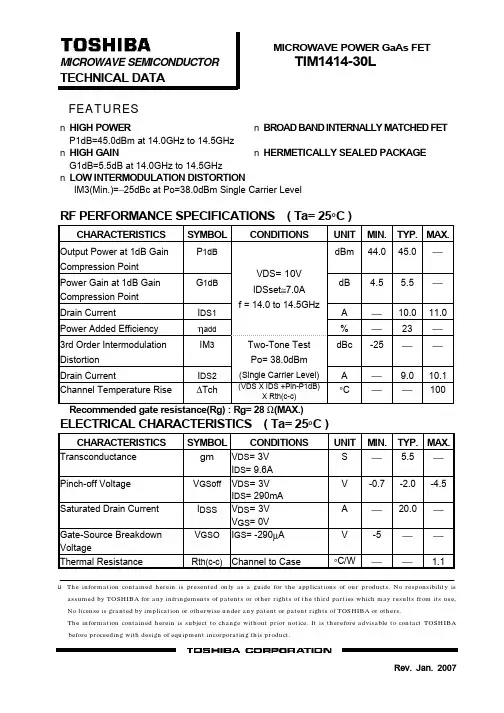
MICROWAVE POWER GaAs FET MICROWAVE SEMICONDUCTOR
TIM1414-30L
TECHNICAL DATA FEATURES
n HIGH POWER n BROAD BAND INTERNALLY MATCHED FET P1dB=45.0dBm at 14.0GHz to 14.5GHz n HIGH GAIN n HERMETICALLY SEALED PACKAGE G1dB=5.5dB at 14.0GHz to 14.5GHz n LOW INTERMODULATION DISTORTION IM3(Min.)=−25dBc at Po=38.0dBm Single Carrier Level
ηadd
IM3
dBc A °C
Recommended gate resistance(Rg) : Rg= 28 Ω(MAX.)
ELECTRICAL CHARACTERISTICS ( Ta= 25°C )
CHARACTERISTICS Transconductance Pinch-off Voltage Saturated Drain Current Gate-Source Breakdown Voltage Thermal Resistance SYMBOL CONDITIONS VDS= 3V IDS= 9.6A VDS= 3V IDS= 290mA VDS= 3V VGS= 0V IGS= -290µA UNIT S V A V °C/W MIN. -0.7 -5 TYP. MAX. 5.5 -2.0 20.0 -4.5 1.1
PACKAGE OUTLINE (7-AA03A)
Philips 65BDL3017P 电视机用户手册(英文)说明书

ProfessionalDisplay SolutionsP Line65BDL3017PUser Manual (English) /welcome65BDL3017PSafety InstructionsSafety precautions and maintenanceWARNING: Use of controls, adjustments or procedures other than those specified in this documentation mayresult in exposure to shock, electrical hazards and/or mechanical hazards.Read and follow these instructions when connecting and using your display:Operation:• Keep the display out of direct sunlight and away from stoves or any other heat sources.• Keep the display away from oil, otherwise the plastic cover may be damaged.• It is recommended to set the display up in the well-ventilated place.• Ultra-violet ray filter is necessary of outdoor operation.• If the product will be used in extreme conditions such as high temperature, humidity, display patterns or operation time etc... It is strongly recommended to contact Philips for Application engineering advice. Otherwise, its reliability and function may not be guaranteed. Extreme conditions are commonly found at Airports, Transit Stations, Banks, Stock market, and Controlling systems.• Remove any object that could fall into ventilation holes or prevent proper cooling of the display’s electronics.• Do not block the ventilation holes on the cabinet.• When positioning the display, make sure the power plug and outlet are easily accessible.• When turning off the display by detaching the power cord, wait 6 seconds before re-attaching the power cord for normal operation.• Ensure the use of an approved power cord provided by Philips at all times. If your power cord is missing, please contact your local service center.• Do not subject the display to severe vibration or high impact conditions during operation.• Do not knock or drop the display during operation or transportation.• The eye bolt is for usage in short-time maintenance and installation. We suggest not to use the eye bolt for more than 1 hour.Prolong usage is prohibited. Please keep a clear safety area under the display while using the eye bolt.Maintenance:• To protect your display from possible damage, do not put excessive pressure on the LCD panel. When moving your display, grasp the frame to lift; do not lift the display by placing your hand or fingers on the LCD panel.• Unplug the display if you are not going to use it for an extensive period of time.• Unplug the display if you need to clean it with a slightly damp cloth. The screen may be wiped with a dry cloth when the power is off. However, never use organic solvent, such as, alcohol, or ammonia-based liquids to clean your display.• To avoid the risk of shock or permanent damage to the set, do not expose the display to dust, rain, water or an excessively moist environment.• If your display becomes wet, wipe it with dry cloth as soon as possible.• If a foreign substance or water gets in your display, turn the power off immediately and disconnect the power cord. Then remove the foreign substance or water, and send the unit to the maintenance center.• Do not store or use the display in locations exposed to heat, direct sunlight or extreme cold.• In order to maintain the best performance of your display and ensure a longer lifetime, we strongly recommend using the display in a location that falls within the following temperature and humidity ranges.Environmental absolute ratingsItem Min. Max. UnitStorage temperature-2065°COperation temperature040°CGlass Suraface temperature065°C(Operation)Storage humidity590% RHOperating humidity2080% RH• LCD panel temperature need to be 25 degrees Celsius at all time for better luminance performance.65BDL3017P • Only the lifetime of the display stated in this specification is guaranteed if the display is used under the proper operationconditions.IMPORTANT: Always activate a moving screen saver program when you leave your display unattended. Always activate a periodic screen refresh application if the unit will display unchanging static content. Uninterrupted display of still or static images over an extended period may cause “burn in”, also known as “after-imaging” or “ghost imaging”, on your screen. This is a well-known phenomenon in LCD panel technology. In most cases, the “burned in” or “after-imaging” or “ghost imaging” will disappear gradually over a period of time after the power has been switched off.WARNING: Severe “burn-in” or “after-image” or “ghost image” symptoms will not disappear and cannot be repaired. This is also not covered under the terms of your warranty.Service:• The casing cover should be opened only by qualified service personnel.• If there is any need for repair or integration, please contact your local service center.• Do not leave your display under direct sunlight.If your display does not operate normally, having followed the instructions set out in this document, pleasecontact a technician or your local service center.Stability Hazard.The device may fall, causing serious personal injury or death. To prevent injury, this device must be securely attached to the floor/wall in accordance with the installation instructions.Read and follow these instructions when connecting and using your display:• Unplug the display if you are not going to use it for an extensive period of time.• Unplug the display if you need to clean it with a slightly damp cloth. The screen many be wiped with a dry cloth when the power is off. However, never use alcohol, solvents or ammonia-based liquids.• Consult a service technician if the display does not operate normally when you have followed the instructions in this manual.• The casing cover should be opened only by qualified service personnel.• Keep the display out of direct sunlight and away from stoves or any other heat sources.• Remove any object that could fall into the vents or prevent proper cooling of the display’s electronics.• Do not block the ventilation holes on the cabinet.• Keep the display dry. To avoid electric shock, do not expose it to rain or excessive moisture.• When turning off the display by detaching the power cable or DC power cord, wait for 6 seconds before re-attaching the power cable or DC power cord for normal operation..• To avoid the risk of shock or permanent damage to the set do not expose the display to rain or excessive moisture.• When positioning the display, make sure the power plug and outlet are easily accessible.• IMPORTANT: Always activate a screen saver program during your application. If a still image in high contrast remains on the screen for an extended period of time, it may leave an ‘after-image’ or ‘ghost image’ on thefront of the screen. This is a well-known phenomenon that is caused by the shortcomings inherent in LCDtechnology. In most cases the afterimage will disappear gradually over a period of time after the power hasbeen switched off. Be aware that the after-image symptom cannot be repaired and is not covered underwarranty.• If provided with a 3-pin attachment plug on the power cord, plug the cord into a grounded (earthed) 3-pin outlet. Do not disable the power cord grounding pin, for example, by attaching a 2-pin adapter. The groundingpin is an important safety feature.EU Declaration of ConformityThis device complies with the requirements set out in the Council Directive on the Approximation of the Laws of the Member States relating to Electromagnetic Compatibility (2014/30/EU), Low-voltage Directive (2014/35/EU), RoHS directive (2011/65/ EU).This product has been tested and found to comply with the harmonized standards for Information Technology Equipment, these harmonized standards published under Directives of Official Journal of the European Union.ESD WarningsWhen user close to the monitor may cause the equipment discharge and reboot to the display of main menu.65BDL3017PWarning:This equipment is compliant with Class A of EN55032/CISPR 32. In a residential environment this equipment may cause radio interference.Federal Communications Commission (FCC) Notice (U.S. Only)NOTE: This equipment has been tested and found to comply with the limits for a Class A digital device,pursuant to part 15 of the FCC Rules. These limits are designed to provide reasonable protection against harmfulinterference when the equipment is operated in a commercial environment. This equipment generates, uses, andcan radiate radio frequency energy and, if not installed and used in accordance with the instruction manual, maycause harmful interference to radio communications. Operation of this equipment in a residential area is likely tocause harmful interference in which case the user will be required to correct the interference at his own expense.Changes or modifications not expressly approved by the party responsible for compliance could void the user’sauthority to operate the equipment.Use only an RF shielded cable that was supplied with the display when connecting this display to a computer device.To prevent damage which may result in fire or shock hazard, do not expose this appliance to rain or excessive moisture.This device complies with Part 15 of the FCC Rules. Operation is subject to the following two conditions: (1) This device may not cause harmful interference, and (2) this device must accept any interference received, including interference that may cause undesired operation.Envision Peripherals Inc.490 N McCarthy Blvd, Suite #120Milpitas, CA 95035USA65BDL3017P Polish Center for Testing and Certification NoticeThe equipment should draw power from a socket with an attached protection circuit (a three-prong socket). All equipment that works together (computer, display, printer, and so on) should have the same power supply source.The phasing conductor of the room’s electrical installation should have a reserve short-circuit protection device in the form of a fuse with a nominal value no larger than 16 amperes (A).To completely switch off the equipment, the power supply cable must be removed from the power supply socket, which should be located near the equipment and easily accessible.A protection mark “B” confirms that the equipment is in compliance with the protection usage requirements of standards PN-93/T-42107 and PN-89/E-06251.Electric, Magnetic and Electromagnetic Fields (“EMF”)1. We manufacture and sell many products targeted at consumers, which, like any electronic apparatus, in general have theability to emit and receive electromagnetic signals.2. One of our leading Business Principles is to take all necessary health and safety measures for our products, to comply withall applicable legal requirements and to stay well within the EMF standards applicable at the time of producing the products.3. We are committed to develop, produce and market products that cause no adverse health effects.4. We confirm that if its products are handled properly for their intended use, they are safe to use according to scientificevidence available today.5. We play an active role in the development of international EMF and safety standards, enabling us to anticipate furtherdevelopments in standardization for early integration in its products.65BDL3017PInformation for U.K. onlyWARNING - THIS APPLIANCE MUST BE EARTHED.Important:This apparatus is supplied with an approved moulded 13A plug. To change a fuse inthis type of plug proceed as follows:+1. Remove fuse cover and fuse.2. Fit new fuse which should be a BS 1362 5A,A.S.T.A. or BSI approved type.3. Refit the fuse cover.If the fitted plug is not suitable for your socket outlets, it should be cut off and anappropriate 3-pin plug fitted in its place.If the mains plug contains a fuse, this should have a value of 5A. If a plug without afuse is used, the fuse at the distribution board should not be greater than 5A.Note: The severed plug must be destroyed to avoid a possible shock hazard should itbe inserted into a 13A socket elsewhere.How to connect a plugThe wires in the mains lead are coloured in accordance with the following code:BLUE - “NEUTRAL” (“N”)BROWN - “LIVE” (“L”)GREEN & YELLOW - “EARTH” (“E”)1. The GREEN & YELLOW wire must be connected to the terminal in the plug which ismarked with the letter “E” or by the Earth symbol or coloured GREEN or GREEN &YELLOW.2. The BLUE wire must be connected to the terminal which is marked with the letter“N” or coloured BLACK.3. The BROWN wire must be connected to the terminal which marked with the letter“L” or coloured RED.Before replacing the plug cover, make certain that the cord grip is clamped over thesheath of the lead - not simply over the three wires.North Europe (Nordic Countries) InformationPlacering/VentilationVARNING:FÖRSÄKRA DIG OM ATT HUVUDBRYTARE OCH UTTAG ÄR LÄTÅTKOMLIGA, NÄR DU STÄLLER DIN UTRUSTNING PÅPLATS.Placering/VentilationADVARSEL:SØRG VED PLACERINGEN FOR, AT NETLEDNINGENS STIK OG STIKKONTAKT ER NEMT TILGÆNGELIGE.Paikka/IlmankiertoVAROITUS:SIJOITA LAITE SITEN, ETTÄ VERKKOJOHTO VOIDAAN TARVITTAESSA HELPOSTI IRROTTAA PISTORASIASTA.Plassering/VentilasjonADVARSEL:NÅR DETTE UTSTYRET PLASSERES, MÅ DU PASSE PÅ AT KONTAKTENE FOR STØMTILFØRSEL ER LETTE Å NÅ.65BDL3017P China RoHS根据中国大陆《电器电子产品有害物质限制使用管理办法》,以下部分列出了本产品中可能包含的有害物质的名称和含量。
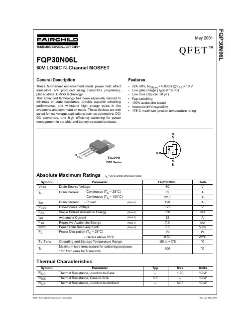
FQP30N06L中文资料
Min Typ Max Units
Off Characteristics
BVDSS ∆BVDSS / ∆TJ
Drain-Source Breakdown Voltage
Breakdown Voltage Temperature Coefficient
VGS = 0 V, ID = 250 µA
D
!
"
!"
G!
" "
!
S
FQP30N06L 60 32 22.6 128 ± 20 350 32 7.9 7.0 79 0.53
-55 to +175
300
Typ
Max
--
1.90
0.5
--
--
62.5
Units V A A A V mJ A mJ
V/ns W
W/°C °C
°C
Units °C/W °C/W °C/W
102
101
175℃
100
0.4
0.6
25℃
※ Notes :
1. VGS = 0V 2. 250μ s Pulse Test
0.8
1.0
1.2
1.4
1.6
VSD, Source-Drain voltage [V]
Figure 4. Body Diode Forward Voltage Variation vs. Source Current and Temperature
Figure 5. Capacitance Characteristics
Capacitance [pF]
©2001 Fairchild Semiconductor Corporation
SONY PMW-330K 330L 说明书
Printed in Japan 使用再生纸印刷。
41989410104-198-941-01 (1)存储卡摄录一体机使用说明书使用产品前请仔细阅读本使用说明书,并请妥善保管。
PMW-330K PMW-330L © 2010 Sony Corporation 产品中有毒有害物质或元素的名称及含量使用环境条件:参考使用说明书中的工作条件a ︰表示该有毒有害物质在该部件所有均质材料中的含量均在 SJ/T11363-2006标准规定的限量要求以下。
× ︰表示该有毒有害物质至少在该部件的某一均质材料中的含量超出 SJ/T11363-2006 标准规定的限量要求。
部件名称有毒有害物质或元素铅 (Pb) 汞 (Hg) 镉 (Cd)六价铬 (Cr (VI)) 多溴联苯 (PBB) 多溴二苯醚(PBDE)实装基板×a a a a a 外壳×a a a a a 显示屏×a a a a a 光学组件×a ×a a a 附属品×a a a a aDraft警告为减少火灾或电击危险,请勿让本设备受到雨淋或受潮。
为防止触电严禁拆开机壳,维修请咨询具备资格人士。
注意用户不得自行更换电池,应交由合格维修人员进行。
如果电池更换不当会有爆炸危险。
只能用同样类型或等效类型的电池来更换。
2目录前言 (9)使用之前 (9)第 1 章概述特点 (10)使用软件 (11)阅读CD-ROM手册 (11)使用这些应用程序的系统要求 (12)软件安装 (12)部件及控件的位置和功能 (13)电源 (13)附件连接 (13)操作和接口部分 (14)单色 LCD 面板 (22)自动调焦镜头(随PMW-330K附带) (23)取景器 (24)取景器屏幕显示 (25)第 2 章准备工作准备电源 (29)使用电池 (29)使用 AC 电源 (30)安装取景器 (30)安装附带的取景器 (30)调整取景器位置 (31)调整取景器角度 (31)升起取景器镜筒和接目镜 (31)调节取景器焦距和屏幕 (33)使用 BKW-401 取景器旋转架 (33)安装5英寸电子取景器 (34)设置使用区域 (35)设置内部时钟的日期/时间 (36)安装后调整镜头 (36)调整基面焦距 (37)目录3准备音频输入系统 (38)将麦克风连接到MIC IN接口 (38)将麦克风连接到AUDIO IN接口 (38)连接UHF 便携式调谐器(用于 UHF 无线麦克风系统) (39)三脚架安装 (40)连接视频灯 (41)使用肩带 (42)调节肩托位置 (42)第 3 章调整和设置设置视频格式 (43)更改视频格式 (44)调整黑平衡和白平衡 (44)调整黑平衡 (44)调整白平衡 (45)设置电子快门 (47)快门模式 (47)选择快门模式和快门速度 (48)更改自动光圈调整的参考值 (49)变焦 (50)在变焦模式之间切换 (50)使用手动变焦 (50)使用伺服变焦 (50)调整聚焦 (50)Full MF模式中的调整 (50)MF模式中的调整 (51)AF模式中的调整 (51)使用微距模式 (51)调整音频电平 (52)手动调整 AUDIO IN CH1/CH2 接口音频输入的音频电平 (52)手动调整MIC IN接口的音频电平 (52)记录通道 3 和 4 中的音频 (53)设置时间数据 (54)设置时间代码 (54)设置用户位 (54)同步时间代码 (54)检查摄像机设定和状态信息(状态屏幕) (56)4目录第 4 章拍摄使用S×S内存卡 (58)关于S×S内存卡 (58)装入和弹出S×S内存卡 (59)选择要使用的S×S内存卡 (60)格式化(初始化)S×S内存卡 (60)检查剩余记录时间 (60)恢复S×S内存卡 (60)基本操作 (61)播放已记录的剪辑 (62)删除记录的剪辑 (63)高级操作 (63)记录拍摄标记 (63)设置OK标记 (63)开始从预存视频记录(图像缓存功能) (64)记录时间不连续的视频(Interval Rec(间隔记录)功能) (65)拍摄定格动画(帧记录功能) (66)慢动作和快动作拍摄 (67)用Freeze Mix功能进行帧拍摄 (68)第 5 章剪辑操作剪辑播放 (69)缩略图屏幕 (69)播放剪辑 (71)使用缩略图在剪辑内搜索 (72)缩略图操作 (73)缩略图菜单配置 (73)基本缩略图菜单操作 (74)更改缩略图屏幕类型 (74)显示剪辑属性 (75)添加并删除OK标记(仅限HD模式) (76)片段复制 (76)删除剪辑 (77)显示扩展缩略图屏幕 (77)显示拍摄标记缩略图屏幕(仅限HD模式) (78)添加并删除拍摄标记(仅限HD模式) (79)更改剪辑索引图像(仅限HD模式) (79)分割模式(仅限HD模式) (79)目录5第 6 章菜单和详细设置设置菜单结构和等级 (80)设置菜单的结构 (80)设置菜单层 (80)基本设置菜单操作 (81)菜单列表 (84)操作菜单 (84)画质设定菜单 (95)维护菜单 (99)文件菜单 (108)为自定义开关指定功能 (111)可以指定给ASSIGN. 0开关的功能 (111)可以指定给ASSIGN. 2开关的功能 (112)可以指定给ASSIGN. 1和3开关、ASSIGNABLE 4和5开关、以及COLOR TEMP.键的功能 (112)可以指定给镜头上的RET键的功能 (114)调节图像特性以与PMW-EX1R一致 (115)第 7 章保存和加载用户设定数据保存和加载设置 (116)保存设置数据 (116)加载设置数据 (117)重置内容被更改后的文件 (117)保存或加载场景文件 (118)保存场景文件 (118)加载场景文件 (118)保存或加载镜头文件 (119)设置镜头文件数据 (119)保存镜头文件 (119)加载镜头文件 (119)自动加载镜头文件 (120)第 8 章连接外部设备连接外部监视器 (121)用电脑操作剪辑 (123)连接外部设备(i.LINK连接) (125)将摄像机图像记录在外部设备上 (125)6目录非线性编辑 (125)记录外部输入信号 (126)使用外置硬盘 (126)安装/取下PHU-60K/120K/120R (126)格式化PHU-60K/120K/120R (127)修复PHU-60K/120K/120R (128)使用介质适配器 (128)格式化 (128)通过RM-B150/B750进行操作 (129)通过RM-B150/B750调整摄像机 (129)通过RM-B150操作菜单 (131)通过RM-B750操作菜单 (131)可通过RM-B150/B750控制的功能 (132)第 9 章维护测试摄像机 (139)维护 (139)清洁取景器 (139)关于电池端子的注意事项 (139)操作警告 (140)附录有关操作的重要事项 (146)更换内部时钟的电池 (148)输出格式和限制 (149)视频格式和输出信号 (149)规格说明 (157)一般规格 (157)摄像机部分 (157)音频部分 (158)显示 (158)介质部分 (158)输入/输出 (158)镜头部分(仅限PMW-330K) (159)提供的附件 (159)建议可选设备 (159)选购元件和附件表 (161)关于i.LINK (162)目录7MPEG-2 Video Patent Portfolio许可证 (163)索引 (164)8目录前言使用之前购买存储卡摄录一体机PMW-330K/330L后,必须在操作前设置使用区域。
HR30-6R-6P中文资料
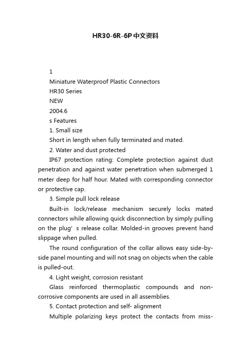
HR30-6R-6P中文资料1Miniature Waterproof Plastic ConnectorsHR30 SeriesNEW2004.6s Features1. Small sizeShort in length when fully terminated and mated.2. Water and dust protectedIP67 protection rating: Complete protection against dust penetration and against water penetration when submerged 1 meter deep for half hour. Mated with corresponding connector or protective cap.3. Simple pull lock releaseBuilt-in lock/release mechanism securely locks mated connectors while allowing quick disconnection by simply pulling on the plug’s release collar. Molded-in grooves prevent hand slippage when pulled.The round configuration of the collar allows easy side-by-side panel mounting and will not snag on objects when the cable is pulled-out.4. Light weight, corrosion resistantGlass reinforced thermoplastic compounds and non-corrosive components are used in all assemblies.5. Contact protection and self- alignmentMultiple polarizing keys protect the contacts from miss-alignment or attempted insertion of the wrong connector,while assuring correct mating between the corresponding connectors.6. Visual alignment indicatorsPermanent alignment indicators in a contrasting color on all connectors aid in correct alignment and engagement.7. Built-in cable strain relief s ApplicationsTest and measuring equipment, portable devices,instrumentation, industrial devices, recreational equipment,I/O applications and other applications requiring use of lightweight, corrosion resistant quick mate/ release cableconnections.Push-pull- single action lock15.542.112.632.33 and 6 pos.10 and 12 pos.Mated dimensionsLock/release operationPush-pull locking collar元器件交易网2s Product Specificationss Ordering informationHR 3 0 - 6 P A - 6 S C3s Plugsq Solder T ypeHR30-7P-12SC (Shown)Shown with terminated and installed contacts.Note: Crimp contacts are not included. Please order applicable contacts separately.HR30-6P-6S (Shown)4s Receptaclesq Solder TypeGasketBCADE(Thread)F(Hex nut)Lock washer12345HR30-6R-6P (Shown)q Through hole TypeHR30-8R-12SD (Shown)DCAB2Through hole post(0.2∞0.5)EF(Hex nut)GasketLock washerHR30-7R-12PC (Shown)Shown with terminated and installed contacts. Shown with terminated and installed contacts. Shown with terminated and installed contacts. Shown with terminated and installed contacts. Shown with terminated and installed contacts. Shown with terminated and installed contacts.5q Solder T ypeB(Fully tightened)A3456Applicablecable diameterHR30-7J-12PC (Shown)HR30-6J-6P (Shown)Shown with terminated and installed contacts.Note: Crimp contacts are not included. Please order applicable contacts separately.6q For Plugs11.4CABDEHR30-6R-CHR30-6P-CNote : When using these caps, do not use the gasket that is normally supplied with the receptacle. The “B” diameter end ofthe receptacle cap will serve as the gasket.7Note :Use wire size AWG 26 to 30 with a jacket diameter of 1 mm max.s Crimp ContactsB Connecting Combinations0.82111.151.2A-A cross-sectionAAPlugsHR30-*P-**Caps for Plug HR30-*P-CReceptacles HR30-*R-**JacksHR30-*J-**Caps for Receptacle HR30-*R-CCable(Shown for reference only.)CapCapPanel(Shown for reference only.)Male contactFemale contactNote 1 :When selecting connectors, take into account the shell size, contact count and gender of the contacts.Note 2 :When using the protective caps for the receptacles, do not use the gaskets normally supplied with the receptacle. Protective caps mustbe fully inserted to assure specified IP67 water and dust protection.8B Applicable Fixturesq Solder termination fixtureNote :The back shell tightening collar is used to tighten the back shell to the specified torque.Refer to assembly procedures.q Tightening collar for back shellSolder termination fixture Back shell tightening collar Note: The back shell tightening collar is used to tighten the back shell to specified torque.Refer to assembly procedures.HR30-6P-6S-T01HR30-6R-6P-T01HR30-6P-T029s Applicable ToolsNotes 1.The contact configuration depicts a view from the wiring side.2. Mounting to the panel is accomplished by tightening the hexagonal nut from the rear side of the panel.Manual contact crimping tool HT-102/HR30-1 Automatic contact crimping machine CM-105 Contact extraction tool HR30-TP10B Assembly Procedures1112B General usage notesB Precautions1. Do NOT apply force in excess of 30N in the directions shown below.2. To maintain the water/dust protection performance and the cable clamp force, use a cable that is within the range of applicable cable diameter.3. Consult HRS representative when using different cables.Panel30 N max.30 N max.30 N max.The contents of this catalog are current as of date of publication. Contents are subject to change without notice forthe purpose of improvements.5-23,OSAKI 5-CHOME,SHINAGAWA-KU,TOKYO 141-8587,JAPANPHONE: 81-3-3491-9741, FAX: 81-3-3493-2933。
PH8030L中文资料
1.Product profile1.1General descriptionLogic level N-channel enhancement mode Field-Effect Transistor (FET) in a plastic package using T renchMOS technology.1.2Features1.3Applications1.4Quick reference data2.Pinning informationPH8030LN-channel TrenchMOS logic level FETRev. 01 — 6 February 2006Product data sheets Optimized for use in DC-to-DC converterss Very low switching and conduction lossess Logic level compatibles Lead-free packages DC-to-DC converters s Switched-mode power supplies s Voltage regulatorss Notebook computerss V DS ≤30Vs I D ≤76.7As R DSon ≤5.9m Ωs Q GD =3.1nC (typ)Table 1:Pinning Pin Description Simplified outline Symbol1, 2, 3source (S)SOT669 (LFPAK)4gate (G)mbmounting base; connected to drain (D)mb1234SDGmbb0763.Ordering information4.Limiting valuesTable 2:Ordering informationType numberPackage NameDescriptionVersion PH8030LLFP AKplastic single-ended surface mounted package (LFP AK); 4 leadsSOT669Table 3:Limiting valuesIn accordance with the Absolute Maximum Rating System (IEC 60134).Symbol Parameter Conditions Min Max Unit V DS drain-source voltage 25°C ≤T j ≤150°C-30V V DGR drain-gate voltage (DC)25°C ≤T j ≤150°C; R GS =20k Ω-30V V GS gate-source voltage -±20V I D drain current T mb =25°C; V GS =10V; see Figure 2 and 3-76.7A T mb =100°C; V GS =10V; see Figure 2-48.5A I DM peak drain current T mb =25°C; pulsed; t p ≤10µs; see Figure 3-300A P tot total power dissipation T mb =25°C; see Figure 1-62.5W T stg storage temperature −55+150°C T j junction temperature −55+150°C Source-drain diodeI S source current T mb =25°C-52A I SMpeak source currentT mb =25°C; pulsed; t p ≤10µs -208A Avalanche ruggednessE DS(AL)S non-repetitive drain-sourceavalanche energyunclamped inductive load; I D =31A;t p =0.14ms; V DS ≤30V; R GS =50Ω;V GS =10V; starting at T j =25°C-95mJFig 1.Normalized total power dissipation as afunction of mounting base temperatureFig 2.Normalized continuous drain current as afunction of mounting base temperatureT mb =25°C; I DM is single pulseFig 3.Safe operating area; continuous and peak drain currents as a function of drain-source voltage03aa1504080120050100150200T mb P der (%)(°C)03aa234080120050100150200(%)I der T mb (°C)P der P totP tot 25C °()------------------------100%×=I der I DI D 25C °()--------------------100%×=003aab24510-111010210310-11 10102V DS (V)I D (A)DC1 ms 100 µsLimit R DSon = V DS / I D10 ms 100 ms10 µs t p =5.Thermal characteristicsTable 4:Thermal characteristicsSymbol ParameterConditionsMin Typ Max Unit R th(j-mb)thermal resistance from junction to mounting base see Figure 4--2K/WFig 4.Transient thermal impedance from junction to mounting base as a function of pulse duration003aab24610-210-111010-510-410-310-210-1110t p (s)Z th(j-mb) (K/W)single pulse0.20.10.05δ = 0.50.02t pTPtt p Tδ =6.CharacteristicsTable 5:CharacteristicsT j=25°C unless otherwise specified.Symbol Parameter Conditions Min Typ Max Unit Static characteristicsV(BR)DSS drain-source breakdownvoltage I D=250µA; V GS=0VT j=25°C30--V T j=−55°C27--VV GS(th)gate-source threshold voltage I D=1mA; V DS=V GS; see Figure9 and10T j=25°C 1.3 1.7 2.15VT j=150°C0.8--VT j=−55°C-- 2.6V I DSS drain leakage current V DS=30V; V GS=0VT j=25°C--1µAT j=150°C--100µA I GSS gate leakage current V GS=±16V; V DS=0V--100nA R G gate resistance f=1MHz- 1.75-ΩR DSon drain-source on-stateresistance V GS=10V; I D=25A; see Figure6 and8T j=25°C- 4.7 5.9mΩT j=150°C-8.510.6mΩV GS=4.5V; I D=25A; see Figure6 and8-7.39.7mΩDynamic characteristicsQ G(tot)total gate charge I D=25A; V DS=12V; V GS=4.5V;see Figure11 and12-15.2-nCQ GS gate-source charge-8.5-nC Q GS1pre-V GS(th) gate-source charge- 4.1-nC Q GS2post-V GS(th) gate-source charge- 4.4-nC Q GD gate-drain charge- 3.1-nC V GS(pl)gate-source plateau voltage- 3.5-V Q G(tot)total gate charge I D=0A; V DS=0V; V GS=4.5V-14-nCC iss input capacitance V GS=0V; V DS=12V; f=1MHz;see Figure14-2260-pFC oss output capacitance-460-pF C rss reverse transfer capacitance-210-pF C iss input capacitance V GS=0V; V DS=0V; f=1MHz-2540-pFt d(on)turn-on delay time V DS=12V; R L=0.5Ω; V GS=4.5V;R G=5.6Ω-25-nst r rise time-53-ns t d(off)turn-off delay time-27-ns t f fall time-14-ns Source-drain diodeV SD source-drain voltage I S=25A; V GS=0V; see Figure13-0.85 1.2V t rr reverse recovery time I S=20A; dI S/dt=−100A/µs; V GS=0V-34-ns Q r recovered charge-11.5-nCT j =25°C T j =25°CFig 5.Output characteristics: drain current as afunction of drain-source voltage; typical valuesFig 6.Drain-source on-state resistance as a functionof drain current; typical valuesT j =25°C and 150°C; V DS >I D ×R DSonFig 7.Transfer characteristics: drain current as afunction of gate-source voltage; typical valuesFig 8.Normalized drain-source on-state resistancefactor as a function of junction temperature003aab24702040608010000.20.40.60.8V DS (V)I D (A) 3.43.23.6356 2.84.54V GS (V) =10003aab2480481216020406080100I D (A)R DSon (m Ω)3.663.2 3.441054.5V GS (V) =003aab24920406080100012345V GS (V)I D (A)T j = 150 °C25 °C003aab27300.40.81.21.62-60060120180T j (°C)a a R DSonR DSon 25C °()------------------------------=I D =1mA; V DS =V GS T j =25°C; V DS =5VFig 9.Gate-source threshold voltage as a function ofjunction temperatureFig 10.Sub-threshold drain current as a function ofgate-source voltageI D =25A; V DS =12V and 19VFig 11.Gate-source voltage as a function of gatecharge; typical valuesFig 12.Gate charge waveform definitions003aab27200.511.522.53-60060120180T j (°C)V GS(th)(V)maxtypmin003aab27110-610-510-410-300.51 1.522.5V GS (V)I D (A)maxtypmin003aab250246810010203040Q G (nC)V GS (V)I D = 25 A T j = 25 °CV DS = 19 V12 V003aaa508V GSV GS(th)Q GS1Q GS2Q GD V DSQ G(tot)I DQ GSV GS(pl)T j =25°C and 150°C; V GS =0V V GS =0V; f =1MHzFig 13.Source current as a function of source-drainvoltage; typical valuesFig 14.Input,output and reverse transfer capacitancesas a function of drain-source voltage; typical valuesV DS =0V; f =1MHzFig 15.Input and reverse transfer capacitances as a function of gate-source voltage; typical values003aab2510204060801000.20.40.60.811.2V SD (V)I S (A)T j = 25 °C150 °C003aab25210210310410-1110102V DS (V)C (pF)C issC rssC oss003aab25310210310410-1110V GS (V)C (pF)C issC rss7.Package outlineFig 16.Package outline SOT669 (LFPAK)REFERENCESOUTLINE VERSION EUROPEAN PROJECTIONISSUE DATE IECJEDEC JEITASOT669MO-23503-09-1504-10-130 2.5 5 mmscaleeE 1bc 2A 2A 2bcAe UNIT DIMENSIONS (mm are the original dimensions)mm1.100.95A 3A 10.150.001.201.010.500.35b 24.413.62b 32.22.0b 40.90.70.250.19c 20.300.24 4.103.806.25.8H 1.30.8L 20.850.40L 1.30.8L 18°0°w y D (1)5.04.8E (1) 3.33.1E 1(1)D 1(1)max0.254.201.270.250.11234mounting baseD 1cPlastic single-ended surface mounted package (LFPAK); 4 leadsSOT669E b 2b 3b 4HDL 2L 1AAw M CCX1/2 ey Cθθ(A )3LAA 1detail XNote1. Plastic or metal protrusions of 0.15 mm maximum per side are not included.8.Revision historyTable 6:Revision historyDocument ID Release date Data sheet status Change notice Doc. number Supersedes PH8030L_120060206Product data sheet---PH8030L_1© Koninklijke Philips Electronics N.V . 2006. All rights reserved.Product data sheet Rev. 01 — 6 February 200611 of 129.Data sheet status[1]Please consult the most recently issued data sheet before initiating or completing a design.[2]The product status of the device(s) described in this data sheet may have changed since this data sheet was published. The latest information is available on the Internet at URL .[3]For data sheets describing multiple type numbers, the highest-level product status determines the data sheet status.10.DefinitionsShort-form specification —The data in a short-form specification is extracted from a full data sheet with the same type number and title. For detailed information see the relevant data sheet or data handbook.Limiting values definition — Limiting values given are in accordance with the Absolute Maximum Rating System (IEC 60134). Stress above one or more of the limiting values may cause permanent damage to the device.These are stress ratings only and operation of the device at these or at any other conditions above those given in the Characteristics sections of the specification is not implied. Exposure to limiting values for extended periods may affect device reliability.Application information — Applications that are described herein for any of these products are for illustrative purposes only. Philips Semiconductors makes no representation or warranty that such applications will be suitable for the specified use without further testing or modification.11.DisclaimersLife support —These products are not designed for use in life support appliances, devices, or systems where malfunction of these products can reasonably be expected to result in personal injury. Philips Semiconductorscustomers using or selling these products for use in such applications do so at their own risk and agree to fully indemnify Philips Semiconductors for any damages resulting from such application.Right to make changes —Philips Semiconductors reserves the right to make changes in the products - including circuits, standard cells, and/or software - described or contained herein in order to improve design and/or performance. When the product is in full production (status ‘Production’),relevant changes will be communicated via a Customer Product/Process Change Notification (CPCN). Philips Semiconductors assumes noresponsibility or liability for the use of any of these products, conveys no license or title under any patent, copyright, or mask work right to theseproducts,and makes no representations or warranties that these products are free from patent,copyright,or mask work right infringement,unless otherwise specified.12.TrademarksNotice —All referenced brands, product names, service names and trademarks are the property of their respective owners.TrenchMOS —is a trademark of Koninklijke Philips Electronics N.V .13.Contact informationFor additional information, please visit: For sales office addresses, send an email to: sales.addresses@Level Data sheet status [1]Product status [2][3]DefinitionI Objective data Development This data sheet contains data from the objective specification for product development. Philips Semiconductors reserves the right to change the specification in any manner without notice.IIPreliminary dataQualificationThis data sheet contains data from the preliminary specification.Supplementary data will be published at a later date.Philips Semiconductors reserves the right to change the specification without notice,in order to improve the design and supply the best possible product.III Product data ProductionThis data sheet contains data from the product specification. Philips Semiconductors reserves the right to make changes at any time in order to improve the design,manufacturing and supply.Relevant changes will be communicated via a Customer Product/Process Change Notification (CPCN).14.Contents1Product profile. . . . . . . . . . . . . . . . . . . . . . . . . . 11.1General description. . . . . . . . . . . . . . . . . . . . . . 11.2Features . . . . . . . . . . . . . . . . . . . . . . . . . . . . . . 11.3Applications . . . . . . . . . . . . . . . . . . . . . . . . . . . 11.4Quick reference data. . . . . . . . . . . . . . . . . . . . . 12Pinning information. . . . . . . . . . . . . . . . . . . . . . 13Ordering information. . . . . . . . . . . . . . . . . . . . . 24Limiting values. . . . . . . . . . . . . . . . . . . . . . . . . . 25Thermal characteristics. . . . . . . . . . . . . . . . . . . 46Characteristics. . . . . . . . . . . . . . . . . . . . . . . . . . 57Package outline . . . . . . . . . . . . . . . . . . . . . . . . . 98Revision history. . . . . . . . . . . . . . . . . . . . . . . . 109Data sheet status. . . . . . . . . . . . . . . . . . . . . . . 1110Definitions . . . . . . . . . . . . . . . . . . . . . . . . . . . . 1111Disclaimers. . . . . . . . . . . . . . . . . . . . . . . . . . . . 1112Trademarks. . . . . . . . . . . . . . . . . . . . . . . . . . . . 1113Contact information . . . . . . . . . . . . . . . . . . . . 11© Koninklijke Philips Electronics N.V.2006All rights are reserved.Reproduction in whole or in part is prohibited without the priorwritten consent of the copyright owner.The information presented in this document doesnot form part of any quotation or contract,is believed to be accurate and reliable and maybe changed without notice.No liability will be accepted by the publisher for anyconsequence of its use.Publication thereof does not convey nor imply any license underpatent- or other industrial or intellectual property rights.Date of release: 6 February 2006Document number: PH8030L_1Published in The Netherlands。
PW-30中文资料
PW Series•2 watts to 25 watts •0.10 ohms to 30K ohms •±10% or ±5% tolerance•TC’s from 300 ppm/°C to +5500 ppm/°CGeneral NoteWelwyn Components reserves the right to make changes in product specification without notice or liability. All information is subject to Welwyn’s own data and is considered accurate at time of going to print.© Welwyn Components Limited · Bedlington, Northumberland NE22 7AA, UKPW-2PW-3PW-5PW-7PW-10PW-15PW-18PW-22PW-25Power rating at 25°C watts 23571015182225Resistance range ohms 0R15 to 2K40R1 to 7K50R1 to 8K50R1 to 18K 0R18 to 30K 0R18 to 30K 0R18 to 22K 0R27 to 18K 0R27 to 18K Temperature coefficient 0.06%/°C0.15 to 0.990.1 to 0.990.1 to 0.990.1 to 0.990.18 to 0.990.18 to 0.990.18 to 0.990.27 to 1.30.27 to 1.3over R range0.03%/°C 1.0 to 2.4K 1.0 to 7.5K 1.0 to 8.5K 1.0 to 18K 1.0 to 30K 1.0 to 30K 1.0 to 22K 1.5 to 12K 1.5 to 10K +0.55%/°C 0.1 to 300.1 to 860.1 to 680.1 to 1500.1 to 2400.1 to 2400.1 to 2000.15 to 3600.15 to 300+0.45%/°C 0.24 to 1300.1 to 2700.1 to 3000.15 to 6800.24 to 11000.24 to 11000.24 to 11000.36 to 18000.36 to 1200+0.25%/°C1.0 to 100.24 to 200.27 to 221.0 to 511.0 to 821.0 to 821.0 to 701.0 to 1201.5 to 100Electrical DataPhysical DataA subsidiary of TT electronics plc Please note: When ordering the alternative configuration please add an ‘A’ after the part number. (i.e., PW-2A)Dimensions (mm)L ±0.8W ±0.8H ±0.8 d dia. E ±0.8LL min. F (ref.)PW-217.5 6.35 6.350.87.8736.6 1.60PW-322.47.877.870.919.6536.6 1.60PW-522.49.658.640.9110.438.1 1.60PW-735.39.658.640.9111.938.1 3.18PW-1047.89.658.640.9111.938.1 3.18PW-1547.812.712.70.9116.038.1 3.18PW-1847.812.712.70.9116.038.1 3.18PW-2263.512.712.7 1.0*16.038.1 3.18PW-2563.512.712.71.0*16.038.13.18* Copper Clad Steel L0.125 max.dWHLLEFStandard ConfigurationAlternate ConfigurationPW SeriesWelwyn Components10080604020050100150200250Ambient Temperature (°C)P e r c e n t o f R a t e d L o a d254085PW-2PW-3, 5, 7, 10PW-15, 18, 22, 25300250200150100500020406080100120T e m p e r a t u r e R i s e (°C )Percent of Rated LoadPW-22, 25PW-15, 18PW-10PW-7PW-5PW-3Power DeratingTemperature RisePackagingResistors are supplied bulk packed. Quantity 500.PW Series•20 watts to 50 watts •0.10 ohms to 2.0K ohms •±10% or ±5% tolerance •CustomsGeneral NoteWelwyn Components reserves the right to make changes in product specification without notice or liability. All information is subject to Welwyn’s own data and is considered accurate at time of going to print.© Welwyn Components Limited · Bedlington, Northumberland NE22 7AA, UKPW-20EPW-30PW-40PW-50E Power rating at 25°C watts 20304050Resistance rangeohms0R1 to 2K0R5 to 1K20R65 to 1K50R08 to 1K8Electrical DataA subsidiary of TT electronics plc Please note: When ordering the alternative configuration please add an ‘A’ after the part number. (i.e., PW-2A)0.032±0.00250.205 or 0.187±0.0050.157±0.0200.250 (Typ.)0.5±0.0300.5±0.0305/32 Dia. Thru (2)A0.069±0.0050.25±0.0310.032±0.00250.3750.200 (Typ.)0.135±0.0150.250.750.282±0.0200.75±0.0300.75±0.0300.8755/32 Dia. Thru (2)AB 0.125±0.015PW-20E WirewoundPW-30, 40 and 50E WirewoundPW-20E Alternate Terminal Configuration Printed Circuit TerminalDimensions (Inches)A ±0.030B ±0.060PW-20E 1.875 2.50PW-30 2.00 2.55PW-40 2.45 3.00PW-50E 3.0753.6252.000±0.0400.187±0.0101.410±0.0401.050 Min.0.060 Dia. (2)0.500±0.0300.500±0.0300.840±0.0400.250 min.0.020PW-15E100806040200050100150200250Ambient Temperature (°C)P e r c e n t o f R a t e d L o a dPW-20E, PW-30, PW-40PW-50E without bracket3002502001501005000255075100125T e m p e r a t u r e R i s e (°C )Percent of Rated LoadPW-30PW-40PW-50EPW-20EWith Bracket:PW-30 Increased to 40 watts PW-40 Increased to 50 watts PW-50 Increased to 60 wattsPower DeratingTemperature Rise0.250±0.0200.205±0.0200.900±0.0501.106±0.050Meniscus allowable to the termination edgeSee Meniscus Note0.709±0.0300.273±0.010 Dia.0.375±0.0400.125 Rad. (Ref.)0.062 Rad. (2)0.155±0.0050.500±0.0300.290±0.0303.000±0.0402.375±0.0400.500±0.0400.313±0.0500.0200.0200.187±0.0200.060 Dia. (2)0.685±0.0601.000±0.0400.900±0.050PW-30EPackagingResistors are supplied bulk packed. Quantity 500.PW SeriesWelwyn Components。
常用近500个三极管(MOSFET)中文资料
9011,9012,9013,9014,8050,8550三极管的区别9011 NPN 30V 30mA 400mW 150MHz 放大倍数20-809012 PNP 50V 500mA 600mW 低频管放大倍数30-909013 NPN 20V 625mA 500mW 低频管放大倍数40-1109014 NPN 45V 100mA 450mW 150MHz 放大倍数20-908050 NPN 25V 700mA 200mW 150MHz 放大倍数30-1008550 PNP 40V 1500mA 1000mW 200MHz 放大倍数40-140详情如下:90系列三极管参数90系列三极管大多是以90字为开头的,但也有以ST90、C或A90、S90、SS90、UTC90开头的,它们的特性及管脚排列都是一样的。
9011 结构:NPN集电极-发射极电压30V集电极-基电压50V射极-基极电压5V集电极电流0.03A耗散功率0.4W结温150℃特怔频率平均370MHZ放大倍数:D28-45 E39-60 F54-80 G72-108 H97-146 I132-1989012 结构:PNP集电极-发射极电压-30V集电极-基电压-40V射极-基极电压-5V集电极电流0.5A耗散功率0.625W结温150℃特怔频率最小150MHZ放大倍数:D64-91 E78-112 F96-135 G122-166 H144-220 I190-3009013 结构:NPN集电极-发射极电压25V集电极-基电压45V射极-基极电压5V集电极电流0.5A耗散功率0.625W结温150℃特怔频率最小150MHZ放大倍数:D64-91 E78-112 F96-135 G122-166 H144-220 I190-3009014 结构:NPN集电极-发射极电压45V集电极-基电压50V射极-基极电压5V集电极电流0.1A耗散功率0.4W结温150℃特怔频率最小150MHZ放大倍数:A60-150 B100-300 C200-600 D400-10009015 结构:PNP集电极-发射极电压-45V集电极-基电压-50V射极-基极电压-5V集电极电流0.1A耗散功率0.45W结温150℃特怔频率平均300MHZ放大倍数:A60-150 B100-300 C200-600 D400-10009016 结构:NPN集电极-发射极电压20V集电极-基电压30V射极-基极电压5V集电极电流0.025A耗散功率0.4W结温150℃特怔频率平均620MHZ放大倍数:D28-45 E39-60 F54-80 G72-108 H97-146 I132-1989018 结构:NPN集电极-发射极电压15V集电极-基电压30V射极-基极电压5V集电极电流0.05A耗散功率0.4W结温150℃特怔频率平均620MHZ放大倍数:D28-45 E39-60 F54-80 G72-108 H97-146 I132-198三极管85508550是一种常用的普通三极管。
30LV中文资料
440L, 30LV, 30LVS, 25Y, 125L, 20VL Series
Line Rated Disc Capacitors
X & Y EMI/RFI FILTER TYPES: ACROSS-THE-LINE, LINE-BY-PASS, ANTENNA COUPLING
SAFETY AGENCY RECOGNITION AND EMI/RFI FILTERING SUBCLASS
Series / Recognition / Voltage 440L 30LV 30LVS 25Y 125L 20VL Underwriters Laboratories Inc.: (Note 2) UL 1414 Across-The-Line Across-The-Line Across-The-Line — — — — UL 1414 Antenna Coupling Antenna-Coupling Antenna-Coupling — — — — UL 1414 Line-By-Pass Line-By-Pass Line-By-Pass Line-By-Pass Line-By-Pass Line-By-Pass — UL 1414 Rated Voltage 250 VAC 250 VAC 250 VAC 250 VAC 250 VAC — Electromagnetic Interference Filters EMI Filters EMI Filters EMI Filters EMI Filters — EMI Filters UL1283 Rated Voltage 600 VAC 250 VAC 250 VAC 250 VAC — 250 VAC Canadian Standards Association: CSA 22.2 No.1 Across-The-Line Across-The-Line Across-The-Line — — — — CSA 22.2 No.1 Isolation Isolation Isolation Isolation Isolation Isolation — CSA 22.2 No. 1 Rated Voltage 250 VAC 250 VAC 250 VAC 250 VAC 125/250 VAC — CSA 22.2 No. 8 Line-to-Ground Capacitors — Line-To-Ground Line-To-Ground Line-To-Ground — Line-To-Ground For Use in Certified EMI Filters — Certified EMI Filters Certified EMI Filters Certified EMI Filters — Certified EMI Filters CSA 22.2 No. 8 Rated Voltage — 400 VAC 400 VAC 400 VAC — 250 VAC European CENELEC Electronic Components Committee (CECC) EN 132 400 to Publication IEC 384-14 Table II, Edition 2: IEC 384 -14 Second Edition Subclass Y: (Note 3) Y1 Y2 Y2 Y2 Y4 — Subclass Y Voltage (Vrms 50-60 Hz) 500 VAC 300 VAC 250 VAC 250 VAC 125 VAC Type of Insulation Bridged Double or Basic or Basic or Basic or Basic or — Reinforced Supplementary Supplementary Supplementary Supplementary Peak Impulse Voltage Before Endurance Test 8 kV 5 kV 5 kV 5 kV 2.5 kV — IEC 384-14 Second Edition Subclass X: (Note 4) X1 X1 X1 X1 X1 X2 Subclass X Voltage (Vrms 50-60 Hz) 400 VAC 400 VAC 400 VAC 400 VAC 400 VAC 400 VAC Peak Impulse Voltage in Service 2.5 to 4.0 kV 2.5 to 4.0 kV 2.5 to 4.0 kV 2.5 to 4.0 kV 2.5 to 4.0 kV To 2.5 kV Application High Pulse High Pulse High Pulse High Pulse High Pulse Gen. Purpose Damp Heat, Steady State Recognition Code HKF - 25°C/ + 125°C/21 days
- 1、下载文档前请自行甄别文档内容的完整性,平台不提供额外的编辑、内容补充、找答案等附加服务。
- 2、"仅部分预览"的文档,不可在线预览部分如存在完整性等问题,可反馈申请退款(可完整预览的文档不适用该条件!)。
- 3、如文档侵犯您的权益,请联系客服反馈,我们会尽快为您处理(人工客服工作时间:9:00-18:30)。
Document Number: 51056For technical questions, contact: sfer@P30LVishay SferniceLong Life Potentiometer - 1 Million CyclesHeavy Duty - CermetFully SealedFEATURES•1 million cycles•High power rating (2 W at 70 °C)•Low temperature coefficient (± 150 ppm/°C typical)•Custom designs on request For technical questions, contact: sfer@Document Number: 51056P30LVishay SferniceLong Life Potentiometer - 1 Million CyclesHeavy Duty - CermetFully SealedDocument Number: 51056For technical questions, contact: sfer@P30LLong Life Potentiometer - 1 Million CyclesHeavy Duty - CermetFully SealedVishay SferniceMECHANICAL SPECIFICATIONSMechanical Travel300° ± 5Operating Torque (Typical) 3 Ncm max. 4.25 oz.-inch max.End Stop Torque70 Ncm max.99 oz.-inch max.Tightening Torque of Mounting Nut 250 Ncm max.22.13 lb-inch max.Unit Weight 23 to 32 g max.0.8 to 1.13 oz.Terminalse3: pure Sn ENVIRONMENTAL SPECIFICATIONSTemperature Range - 40 °C to 100 °CClimatic Category 40/100/56SealingFully sealed - Container IP67OPTIONSSpecial Feature Command ShaftLength is measured from the mounting surface to the free end of the shaft. The screwdriver slot is aligned with the wiper within ± 10°. Special shafts are available, in accordance to drawings supplied by customers. We recommend that customers should not machine tool shafts, in order to avoid damage. Bending or torsion of terminals should also be avoided.Panel SealingThe panel sealing device consists of a ring located in a groove on the potentiometer face. Sealing is obtained by tightening the ring against the panel when mounting the potentiometer.Locating PegLocation is obtained by fitting a special washer on the mounting face of the potentiometer.MARKING•VISHAY trademark •Model•Ohmic Value code •Tolerance code•Manufacturing date code•Marking of terminals 3, and a, b, c For technical questions, contact: sfer@Document Number: 51056P30LVishay SferniceLong Life Potentiometer - 1 Million CyclesHeavy Duty - CermetFully SealedPERFORMANCESTESTSCONDITIONSΔRT/RT (%)ΔR 1-2/R 1-2 (%)OTHERClimatic Sequence Phase A dry heat 100 °C Phase B damp heat Phase C cold - 40 °C Phase D damp heat 5 cycles± 0.5 %± 1 %-Long Term Damp Heat 56 days 40 °C 93 % HR± 0.5 %± 1 %Insulation resistance >100 M ΩRotational Life 1 000 000 cycles at rated powerTurn angle: ± 60°33 cycles per minute Temperature: 20 °C ± 20 %-Contact resistance variation max. 35 %Independent linearity ± 10 % (T ypical)Load Life 1000 h at rated power90'/30'Ambient temperature 70 °C± 20 %± 20 %Contact resistance variation max. 30%Rapid Temperature Change 5 cycles - 40 °C at 100 °C ± 0.5 %--Shock 50 g at 11 ms 3 successive shocks in 3 directions ± 0.1 %± 0.2 %-Vibration 10 - 55 Hz 0.75 mm or 10 g during 6 h± 0.1 %± 0.2 %-SAP ORDERING INFORMATION (Part Number 18 digits)MODEL BUSHING OPTION SHAFT RESISTANCE CODE / TOLERANCECODE / TAPER SPECIAL NUMBER L = M10 x 0.75M = Panel sealed M10 x 0.750 = None E = With Locating Peg (for M bushing only)L = LPRPDiameter Length End Shaft Shape Ohmic ValueT oleranceVariation Law (if applicable)Given by VISHAY for custom designF = Ø 6 mm AP = Custom shaftFor L Bushing G = 16 mm L = 25 mm R = 50 mm For M Bushing D = 13 mm J = 22 mm P = 47 mmR = Round On request S = Slotted D = Custom end shaft F = Flatted102 = 1 k Ω502 = 5 k Ω103 = 10 k Ω503 = 50 k ΩM = 20 %On request K = 10 %A = linearPART NUMBER DESCRIPTION (for information only)P30L L 0FDR10K20 %A BO10e3MODELBUSHINGOPTION SHAFT VALUE TOLERANCET APERSPECIALPACKAGINGSPECIAL SPECIALLEAD (Pb)-FREELFDR1MPL33ADisclaimer Legal Disclaimer NoticeVishayAll product specifications and data are subject to change without notice.Vishay Intertechnology, Inc., its affiliates, agents, and employees, and all persons acting on its or their behalf (collectively, “Vishay”), disclaim any and all liability for any errors, inaccuracies or incompleteness contained herein or in any other disclosure relating to any product.Vishay disclaims any and all liability arising out of the use or application of any product described herein or of any information provided herein to the maximum extent permitted by law. The product specifications do not expand or otherwise modify Vishay’s terms and conditions of purchase, including but not limited to the warranty expressed therein, which apply to these products.No license, express or implied, by estoppel or otherwise, to any intellectual property rights is granted by this document or by any conduct of Vishay.The products shown herein are not designed for use in medical, life-saving, or life-sustaining applications unless otherwise expressly indicated. Customers using or selling Vishay products not expressly indicated for use in such applications do so entirely at their own risk and agree to fully indemnify Vishay for any damages arising or resulting from such use or sale. Please contact authorized Vishay personnel to obtain written terms and conditions regarding products designed for such applications.Product names and markings noted herein may be trademarks of their respective owners.元器件交易网。