控制器仪表
斯巴拓SBT932F仪表控制器操作说明书使用压力传感器测力称重

:滑动平均滤波+一阶滤波
:中位值平均滤波+一阶滤波
13
F1-13
滤波强度
范围:0~50,数字越大,滤波越强
峰谷值参数(F2)
序号
名称
符号
内容
说明
1
F2-01
峰值检测使能方式
:关闭峰值检测
:力值超过峰值阈值后启动峰值检测
:由外部触发并满足峰值阈值后启动峰值检测
2
F2-02
峰值阈值
:0~20mA
: 4~20mA
: -10V~10V
:-5~5V
2
F8-02
模拟数据源类型
:测量值 :毛重
:净重 :峰值
:谷值 :峰值-谷值
3
F8-03
第一点模拟量
-9.999~25.000
4
F8-04
第二点模拟量
-9.999~25.000
5
F8-05
第一点重量
-99999~999999
6
F8-06
第二点重量
F3-3.4
F3-4.4
F3-5.4
F3-6.4
比较器N比较延时
0~25.5;单位:秒
5
F3-1.5
F3-2.5
F3-3.5
F3-4.5
F3-5.5
F3-6.5
比较器N上限比较值
-99999~999999
6
F3-1.6
F3-2.6
F3-3.6
F3-4.6
F3-5.6
F3-6.6
比较器N中限比较值
-99999~999999
10
F1-10
蠕变跟踪时间
福尔摩斯仪表-数字温度控制器-FX-PXR3说明书
T i me rf unct i on H e a t i n g /c o o li n g c on t ro l f u n c t i o n R am p/s o a kf u n c t i o nU L/C -U L /C E m a r k P ID +fu z z y f u n ct i o n Di g i t a l i npu t Co m m u n i c a t i o nf u n c t i o n R e -T r a n s m i s s i o no u t p u t L ar g e L ED d i sp l a y F r o n t w a t e r p r o o fst r u c t u r e (N E M A -4X /I P 66)S el f -t un i ng ECNO:1138cModel:PXR3(1/32 DIN, 24×48mm)Digital Temperature ControllerMicro Controller XSeries2Large LED display and front waterproof structurePID + self-tuning, PID + fuzzy controlFor calculating the optimum PID parameters, the auto tuning and self-tuning functions are installed. Also, fuzzy control function is a standard feature for suppressing the overshoot and improving the response to disturbance. Thanks to these functions,optimum control parameters suitable for each application is munication function (option)With RS-485 (Modbus »protocol) interface, a connection with computer, touch panel or PLC is allowed.Digital input (option)External digital input allows one of the following functions.● Change the set value (front SV0, SV1 to 3)● Start/stop the control action ● Start/reset the ramp/soak ● Start/stop the auto tuning ● Cancel the alarm latch● Start the incorporated timerNote:The alarm latch means to hold thestatus once alarm is output.The front display and operation section is dust-proof and waterproof conforming to NEMA-4X:IP66. The front panel is washable with water.(*NOTE)(*Note) Provided that the panel is installed with our genuine watertightpacking.Easy-to-see, large LED display (1.3 times larger than current models)● Self-tuningAt power on, changing a set value or during external disturbance, tuning is madeautomatically so that the PID parameters arecould not be optimized.1/32 DIN (24 ×48 mm) temperature controller PXR3● Fuzzy controlSuppresses the overshoot without wasting start up time.Also, quickly reverts to set points at the event of Touch panelFuji Programmable Operation Display (UG series)3Timer function (option)By Digital input, ON-delay or OFF delay timer can be started.That is, relay output is turned on/off after certain period of time preset in parameter dLY1/dLY2. As for relay output, alarm output relays are used. Up to 2 timer outputs can be obtained.Ramp/soak function (option)Changes the set value (SV) as the time elapses according to a predetermined program pattern. The instrument can program up to 8 ramp/soak steps.Heating/cooling control (option)By a single controller both heating and cooling control output are obtained. (Both control outputs 1 and 2 are used.)PXR, Suitable for various temperature controlsPXR3Heat control outputRecorder PHRPXR3PXR3Temp inputcool control outputPV TransmissionSpecifications and performance <General specifications>4PXR3Note 1: For current input connect the supplied 2501 resister at theinput terminal.Note 2: When the measuring range exceeds 1000°C (1832°F), decimalpoint cannot be used.Note: Basic insulation (dielectric strength 1500 V AC) between blocksdelimited by line .Functional insulation (dielectric strength 500 V AC) betweenblocks delimited by line .Non isolated between blocks which are not delimited from eachother.<Caution in use>The following table shows the differences among PX-series models.When replacing the device, be sure to use the one with identical outputspecifications.56Note 1No combination with alarm (2 points) (The code F, G of 9th digit should not be ordered.)Note 2No combination with control output 2 (A, C, E of 7th digit should not be ordered.)Note 3Control output 2, communication, external input 2, 24V power supply.The code A, C, E of 7th digit, A, B, C of 10th digit, M, N, T, V, W of 11th digit should not be ordered.When delivering, the input signal, measuring range and set value are as follows:Thermocoupule input : type K, 0 to 400°C, set value at 0°C Resistance bulb input : 0 to 150°C, set value at 0°C Voltage or current input : 0 to 100%, set value at 0%The input signal of thermocouple and each measuring range should be specified except for the above specifications.When delivering, the control output action is set at reverse for control output 1, set at direct for control output e the front key to change the control action between reverse and direct.7Re-Transmission RecorderPrinted in Japan 2002-9/00FISInformation in this catalog is subject to change without notice.Over-temperature ProtectionAny control system design should take into account that any part of the system has the potential to fail.For temperature control systems, continued heating should be considered the most dangerous condition, and the machine should be designed to automatically stop heating if unregulated due to the failure of the control unit or for any other reason.The following are the most likely causes of unwanted continued heating:1) Controller failure with heating output constantly on2) Disengagement of the temperature sensor from the system 3) A short circuit in the thermocouple wiring4) A valve or switch contact point outside the system is locked to keep the heat switched on.In any application where physical injury or destruction of equipment might occur, we recommend the installation of independent safety equipment, with a separate temperature sensor, to disable the heating circuit in case of overheating.The controller alarm signal is not designed to function as a protective measure in case of controller failure.SPECIAL ATTENTION NEEDED for all Micro Controller X series products(Please read carefully the following instructions.)。
过程控制仪表
第四章过程控制仪表⏹本章提要1.过程控制仪表概述2.DDZ-Ⅲ型调节器3.执行器4.可编程控制器⏹授课内容第一节概述✧过程控制仪表---是实现工业生产过程自动化的重要工具,它被广泛地应用于石油、化工等各工业部门。
在自动控制系统中,过程检测仪表将被控变量转换成电信号或气压信号后,除了送至显示仪表进行指示和记录外,还需送到控制仪表进行自动控制,从而实现生产过程的自动化,使被控变量达到预期的要求。
过程控制仪表包括调节器(也叫控制器)、执行器、操作器,以及可编程调节器等各种新型控制仪表及装置。
过程控制仪表的分类:●按能源形式分类:液动控制仪表、气动控制仪表和电动控制仪表。
●按结构形式分类:基地式控制仪表、单元组合式控制仪表、组件组装式控制仪表、集散控制装置等。
[基地式控制仪表]以指示、记录仪表为主体,附加某些控制机构而组成。
基地式控制仪表特点:—般结构比较简单、价格便宜.它不仅能对某些工艺变量进行指示或记录,而已还具有控制功能,因此它比较适用于单变量的就地控制系统。
目前常使用的XCT系列动圈式控制仪表和TA系列简易式调节器即属此类仪表。
[单元组合式控制仪表]将整套仪表划分成能独立实现一定功能的若干单元,各单元之间采用统一信号进行联系。
使用时可根据控制系统的需要,对各单元进行选择和组合,从而构成多种多样的、复杂程度各异的自动检测和控制系统。
特点:使用灵活,通用性强,同时,使用、维护更作也很方便。
它适用于各种企业的自动控制。
广泛使用的单元组合式控制仪表有电动单元组合仪表(DDZ型)和气动单元组合仪表(QD2型)。
[组件组装式控制仪表]是一种功能分离、结构组件化的成套仪表(或装置)。
它以模拟器件为主,兼用模拟技术和数字技术。
整套仪表(或装置)在结构上由控制柜和操作台组成,控制柜内安装的是具有各种功能的组件板,采用高密度安装,结构紧凑。
这种控制仪表(或装置)特别适用于要求组成各种复杂控制和集中显示操作的大、中型企业的自动控制系统。
[第4讲]-自动化仪表及过程控制-第四章-过程控制仪表
![[第4讲]-自动化仪表及过程控制-第四章-过程控制仪表](https://img.taocdn.com/s3/m/908249a56529647d272852bc.png)
第四章过程控制仪表⏹本章提要1.过程控制仪表概述2.DDZ-Ⅲ型调节器3.执行器4.可编程控制器⏹授课内容第一节概述✧过程控制仪表---是实现工业生产过程自动化的重要工具,它被广泛地应用于石油、化工等各工业部门。
在自动控制系统中,过程检测仪表将被控变量转换成电信号或气压信号后,除了送至显示仪表进行指示和记录外,还需送到控制仪表进行自动控制,从而实现生产过程的自动化,使被控变量达到预期的要求。
过程控制仪表包括调节器(也叫控制器)、执行器、操作器,以及可编程调节器等各种新型控制仪表及装置。
过程控制仪表的分类:●按能源形式分类:液动控制仪表、气动控制仪表和电动控制仪表。
●按结构形式分类:基地式控制仪表、单元组合式控制仪表、组件组装式控制仪表、集散控制装置等。
[基地式控制仪表]以指示、记录仪表为主体,附加某些控制机构而组成。
基地式控制仪表特点:—般结构比较简单、价格便宜.它不仅能对某些工艺变量进行指示或记录,而已还具有控制功能,因此它比较适用于单变量的就地控制系统。
目前常使用的XCT系列动圈式控制仪表和TA系列简易式调节器即属此类仪表。
[单元组合式控制仪表]将整套仪表划分成能独立实现一定功能的若干单元,各单元之间采用统一信号进行联系。
使用时可根据控制系统的需要,对各单元进行选择和组合,从而构成多种多样的、复杂程度各异的自动检测和控制系统。
特点:使用灵活,通用性强,同时,使用、维护更作也很方便。
它适用于各种企业的自动控制。
广泛使用的单元组合式控制仪表有电动单元组合仪表(DDZ型)和气动单元组合仪表(QD2型)。
[组件组装式控制仪表]是一种功能分离、结构组件化的成套仪表(或装置)。
它以模拟器件为主,兼用模拟技术和数字技术。
整套仪表(或装置)在结构上由控制柜和操作台组成,控制柜内安装的是具有各种功能的组件板,采用高密度安装,结构紧凑。
这种控制仪表(或装置)特别适用于要求组成各种复杂控制和集中显示操作的大、中型企业的自动控制系统。
OMEGATM CNi32 1 32 DIN 数字显示仪表控制器说明书
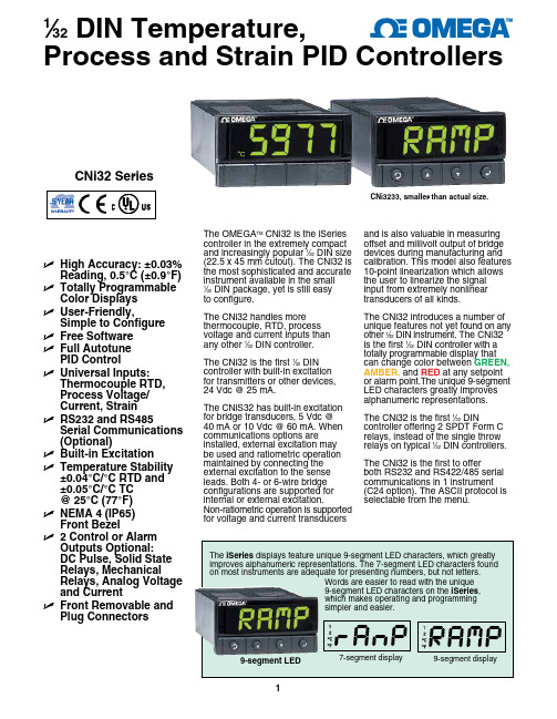
9-segment LEDThe OMEGA TM CNi32 is the iSeries controller in the extremely compact and increasingly popular 1⁄32 DIN size (22.5 x 45 mm cutout). The CNi32 is the most sophisticated and accurate instrument available in the small 1⁄32 DIN package, yet is still easy to configure.The CNi32 handles more thermocouple, RTD, process voltage and current inputs than any other 1⁄32 DIN controller.The CNi32 is the first 1⁄32 DIN controller with built‑in excitation for transmitters or other devices, 24 Vdc @ 25 mA.The CNiS32 has built‑in excitation for bridge transducers, 5 Vdc @ *********************communications options areinstalled, external excitation may be used and ratiometric operation maintained by connecting the external excitation to the sense leads. Both 4‑ or 6‑wire bridge configurations are supported for internal or external excitation.Non‑ratiometric operation is supported for voltage and current transducersand is also valuable in measuring offset and millivolt output of bridge devices during manufacturing and calibration. This model also features 10‑point linearization which allows the user to linearize the signal input from extremely nonlinear transducers of all kinds.The CNi32 introduces a number of unique features not yet found on any other 1⁄32 DIN instrument. The CNi32 is the first 1⁄32 DIN controller with a totally programmable display that can change color between GREEN, AMBER, and RED at any setpoint or alarm point.The unique 9‑segment LED characters greatly improves alphanumeric representations.The CNi32 is the first 1⁄32 DINcontroller offering 2 SPDT Form C relays, instead of the single throw relays on typical 1⁄32 DIN controllers.The CNi32 is the first to offerboth RS232 and RS422/485 serial communications in 1 instrument (C24 option). The ASCII protocol is selectable from the menu.U H igh Accuracy: ±0.03% Reading, 0.5°C (±0.9°F)U T otallyProgrammable Color Displays U U ser-Friendly,Simple to Configure U F ree Software U F ull AutotunePID ControlU U niversal Inputs: Thermocouple RTD, Process Voltage/ Current, Strain U R S232 and RS485Serial Communications (Optional)U B uilt-in Excitation U T emperature Stability ±0.04°C/°C RTD and ±0.05°C/°C TC @ 25°C (77°F)U N EMA 4 (IP65) Front Bezel U 2 Control or Alarm Outputs Optional: DC Pulse, Solid State Relays, Mechanical Relays, Analog Voltage and Current U F ront Removable and Plug ConnectorsCNi3233, smaller than actual size.1⁄32 DIN Temperature,Process and Strain PID ControllersOrdering Examples: CNi3222-C24, 1⁄32 DIN PID controller with 2 solid-state relays for PID control and serial communications, both RS232 and RS485.CNiS322-AL, 1⁄32 DIN strain/process controller, limit alarm version with SSR output.DPi32-B-COVER front panel button cover supplied with eachunit, standard.CNi3233, shown smaller than actual size.CNi3244, shown smaller than actual size.2 “-AL ” option not available on models with analog (option 5) output.3 “-SM ” option not available on CNiS strain/process input models.Universal Temperature and Process Input (DPi/CNi Models)Accuracy: ±0.5°C temp; 0.03% rdg Resolution: 1°/0.1°; 10 µV process Temperature Stability: RTD: 0.04°C/°CTC @ 25°C (77°F): 0.05°C/°C Cold Junction Compensation Process: 50 ppm/°C NMRR: 60 dB CMRR: 120 dBA/D Conversion: Dual slope Reading Rate: 3 samples/s Digital Filter: ProgrammableDisplay: 4‑digit 9‑segment LED 10.2 mm (0.40"); i32, i16, i16D, i8DV 21 mm (0.83"); i8 10.2 mm (0.40") and 21 mm (0.83"); i8DH RED , GREEN, and AMBER programmable colors for process variable, setpoint and temperature unitsInput Types: Thermocouple, RTD, analog voltage, analog currentThermocouple Lead Resistance: 100 Ω maxThermocouple Types (ITS 90): J, K, T, E, R, S, B, C, N, L (J DIN)RTD Input (ITS 68): 100/500/1000 Ω Pt sensor, 2‑, 3‑ or 4‑wire; 0.00385 or 0.00392 curveVoltage Input: 0 to 100 mV, 0 to 1V, 0 to 10 VdcInput Impedance: 10 M Ω for 100 mV 1 M Ω for 1 or 10 VdcCurrent Input: 0 to 20 mA (5 Ω load)Configuration: Single‑ended Polarity: UnipolarStep Response: 0.7 sec for 99.9%Decimal Selection:Temperature: None, 0.1Process: None, 0.1, 0.01 or 0.001Setpoint Adjustment: ‑1999 to 9999 counts Span Adjustment: 0.001 to 9999 countsOffset Adjustment: ‑1999 to 9999Excitation (Not Included withCommunication): 24 Vdc @ 25 mA (not available for low‑power option)Universal Strain and Process Input (DPiS/CNiS Models)Accuracy: 0.03% reading Resolution: 10/1µVTemperature Stability: 50 ppm/°C NMRR: 60 dB CMRR: 120 dBA/D Conversion: Dual slope Reading Rate: 3 samples/s Digital Filter: ProgrammableInput Types: Analog voltage and current Voltage Input: 0 to 100 mVdc, ‑100 mVdc to 1 Vdc, 0 to 10 VdcInput Impedance: 10 M Ω for 100 mV;1 M Ω for 1V or 10 VdcCurrent Input: 0 to 20 mA (5 Ω load)Linearization Points: Up to 10 Configuration: Single‑ended Polarity: UnipolarStep Response: 0.7 sec for 99.9%Decimal Selection: None, 0.1, 0.01 or 0.001Setpoint Adjustment: ‑1999 to 9999 countsSpan Adjustment: 0.001 to 9999 counts Offset Adjustment: ‑1999 to 9999Excitation (Optional In Place Of Communication): 5 Vdc @ 40 mA;10 Vdc @ 60 mAControlAction: Reverse (heat) or direct (cool)Modes: Time and amplitude proportional control; selectable manual or auto PID, proportional, proportional with integral, proportional with derivative and anti‑reset Windup, and on/off Rate: 0 to 399.9 s Reset: 0 to 3999 sCycle Time: 1 to 199 s; set to 0 for on/off Gain: 0.5 to 100% of span; setpoints 1 or 2Damping: 0000 to 0008Soak: 00.00 to 99.59 (HH:MM), or OFF Ramp to Setpoint:00.00 to 99.59 (HH:MM), or OFFAuto Tune: Operator initiated from front panelControl Output 1 and 2Relay: 250 Vac or 30 Vdc @ 3 A (resistive load); configurable for on/off, PID and ramp and soak Output 1: SPDT, can be configured asalarm 1 outputOutput 2: SPDT, can be configured asalarm 2 outputSSR: ******************.5A (resistive load); continuous DC Pulse: Non‑isolated; 10 Vdc @ 20 mA Analog Output (Output 1 Only):Non‑isolated, proportional 0 to 10 Vdc or0 to 20 mA; 500 Ω maxOutput 3 Retransmission:Isolated Analog Voltage and CurrentCurrent: 10 V max @ 20 mA outputVoltage: 20 mA max for 0 to 10 V output Network and Communications Ethernet: Standards compliance IEEE 802.3 10 Base‑T Supported Protocols: TCP/IP, ARP, HTTPGET RS232/RS422/RS485: Selectable from menu; both ASCII and MODBUS protocol selectable from menu; programmable 300 to 19.2 Kb; complete programmable setup capability; program to transmit current display, alarm status, min/max, actual measured input value and status Common Specifications (All i/8, i/16, i/32 DIN)RS485: Addressable from 0 to 199Connection: Screw terminalsAlarm 1 and 2 (Programmable)Type: Same as output 1 and 2Operation: High/low, above/below, band, latch/unlatch, normally open/normally closed and process/deviation; front panel configurationsAnalog Output (Programmable):Non‑isolated, retransmission 0 to 10 Vdc or 0 to 20 mA, 500 Ω max (output 1 only); accuracy is ± 1% of FS when following conditions are satisfied: input is not scaled below 1% of input FS, analog output is not scaled below 3% of output FSGeneralPower: 90 to 240 Vac ±10%, 50 to 400 Hz *, 110 to 300 Vdc, equivalent voltage Low Voltage Power Option: 24 Vac **, 12 to 36 Vdc for DPi/CNi/DPiS/CNiS; 20 to 36 Vdc for dual display, ethernet and isolated analog output from qualified safety approved sourceIsolationPower to Input/Output: 2300 Vac per 1 minute testFor Low Voltage Power Option: 1500 Vac per 1 minute test Power to Relay/SSR Output: 2300 Vac per 1 minute testRelay/SSR to Relay/SSR Output: 2300 Vac per 1 minute test RS232/485 to Input/Output: 500 Vac per 1 minute test Environmental Conditions:All Models: 0 to 55°C (32 to 131°F) 90% RH non‑condensingDual Display Models:0 to 50°C (32 to 122°F), 90% RH non‑condensing (for UL only) Protection:D Pi/CNi/DPiS/CNiS32,16,16D, 8C: NEMA 4X/Type 4 (IP65) front bezel DPi/CNi/DPiS/CNiS8, 8DH, 8DV: NEMA 1/Type 1 front bezelApprovals: UL, C‑UL, CE per2014/35/EU, FM (temperature units only)Dimensions i /8 Series: 48 H x 96 W x 127 mm D(1.89 x 3.78 x 5") i/16 Series: 48 H x 48 W x 127 mm D (1.89 x 1.89 x 5") i/32 Series: 25.4 H x 48 W x 127 mm D (1.0 x 1.89 x 5")Panel Cutouti/8 Series: 45 H x 92 mm W (1.772 x 3.622"), 1⁄8 DINi/16 Series: 45 mm (1.772") square, 1⁄16 DINi/32 Series: 22.5 H x 45 mm W (0.886 x 1.772"), 1⁄32 DIN Weighti /8 Series: 295 g (0.65 lb) i/16 Series: 159 g (0.35 lb) i/32 Series: 127 g (0.28 lb)* No CE compliance above 60 Hz. ** Units can be powered safely with 24 Vac power, but no certification for CE/UL are claimed.。
仪表自动化控制系统故障与维护技术分析

仪表自动化控制系统故障与维护技术分析仪表自动化控制系统是工业生产中非常重要的一个环节,它能够监测和控制工厂中的各种参数,确保生产过程的稳定和高效。
随着设备的老化和工作环境的变化,仪表自动化控制系统也会出现各种故障。
本文将对仪表自动化控制系统的常见故障和维护技术进行分析,以期帮助工程师更好地理解和解决这些问题。
一、仪表自动化控制系统的常见故障1. 仪表传感器故障仪表传感器是仪表自动化控制系统中最常见的故障之一。
传感器的老化、损坏或者不当安装都可能导致传感器的故障,从而影响系统的监测和控制功能。
常见的传感器故障包括信号漂移、失灵、偏差过大等问题。
2. 仪表控制器故障仪表控制器是控制系统中的核心部件,它负责接收传感器信号、进行数据处理,并输出控制信号。
控制器的故障可能导致系统不能正常工作,比如控制输出不稳定、数据传输不畅等问题。
3. 仪表执行机构故障仪表执行机构包括各种执行元件,比如电磁阀、执行器等,它们通过接收控制信号,实现系统的调节和控制。
执行机构的故障可能导致系统的控制信号无法正确执行,从而影响系统的工作状态。
4. 仪表通信故障仪表自动化控制系统通常由多个子系统组成,它们之间通过通信网络进行数据传输和交互。
通信故障可能导致系统各个部件之间无法正常通信,从而使系统失去协调性和一致性。
1. 定期检查和保养定期的检查和保养是避免仪表自动化控制系统故障的重要手段。
工作人员应该按照设备的维护手册和标准,制定维护计划和方案,并对系统中的传感器、控制器、执行机构等进行定期检查和维护。
2. 适时更换老化部件仪表自动化控制系统中的各个部件都会随着使用时间的增加而老化,一些关键部件的老化将直接导致系统故障。
对于已经老化的部件,需要及时更换,以确保系统的正常运行。
3. 加强培训及时地了解和掌握最新的维护技术和知识,对工程师和技术人员的培训也是非常必要的。
只有具备了足够的维护知识和技能,才能更好地应对系统故障和问题。
4. 应用先进技术当前,一些仪表自动化控制系统已经应用了一些先进的维护技术,比如远程诊断、智能维护等。
DY220测力仪表称重控制器显示器
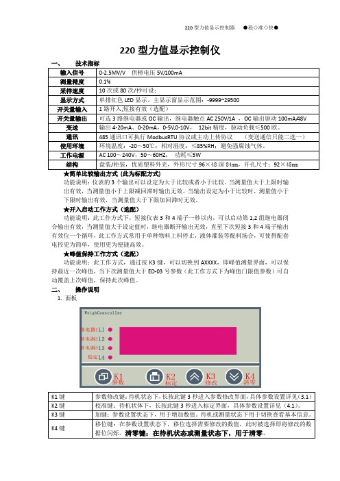
220型力值显示控制仪一、技术指标输入信号0-2.5MV/V 供桥电压5V/100mA测量精度0.1%采样速度10次或80次/秒可设;显示方式单排红色LED显示。
主显示窗显示范围:-9999~29500开关量输入1路开入,短接有效(选配)开关量输出可选3路继电器或OC输出,继电器触点AC 250V/1A ,OC输出驱动100mA/48V 变送输出4-20mA、0-20mA,0-5V,0-10V,12bit精度,驱动负载≤500欧。
通讯485通讯口可执行ModbusRTU协议或主动上传协议(变送通信只能二选一)使用环境环境温度:-20~50℃;相对湿度:≤85%RH;避免强腐蚀气体。
工作电源AC 100~240V,50~60HZ;功耗≤5W结构盘装/柜装,优质塑料外壳,外形尺寸96×48深84mm,开孔尺寸:92×45mm★简单比较输出方式(此为标配方式)功能说明:仪表的3个输出可以设定为大于比较或者小于比较。
当测量值大于上限时输出有效,当测量值小于上限减回滞时输出无效。
当输出设定为小于比较时,测量值小于下限时输出有效,当测量值大于下限加回滞时无效。
★开入启动工作方式(选配)功能说明:此工作方式下,短接仪表3和4端子一秒以内,可以启动第1,2组继电器闭合输出有效,当测量值大于设定值时,继电器断开输出无效,直至下次短接3和4端子输出有效位一个循环,此工作方式常用于单种物料上料停止,液体灌装等配料场合,可使得配套电控更为简单,使用更为便捷高效。
★峰值保持工作方式(选配)功能说明:此工作方式,通过按K3键,可以切换到AXXXX,即峰值测量界面,可以保持最近一次峰值,当下次测量值大于ED-03号参数(此工作方式下为峰值门限值参数)可自动覆盖上次峰值,保持此次峰值。
二、操作说明1. 面板K1键参数修改键:待机状态下,长按此键3秒进入参数修改界面,具体参数设置详见(3.1)K2键校准键:待机状体下,长按此键3秒进入标定界面,具体参数设置详见(4.1)。
汽车仪表盘和控制器说明
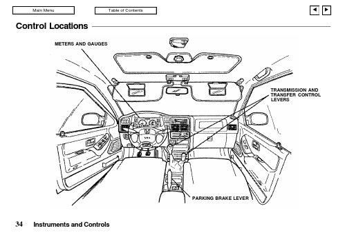
Control LocationsMETERS AND GAUGESTRANSMISSION AND TRANSFER CONTROL LEVERSInstrument s and ControlsPARKING BRAKE LEVERIndicators and GaugesInstruments and ControlsLX and EXHIGH BEAM INDICATOR LIGHTANTI-LOCK BRAKE SYSTEM INDICATOR LIGHT (Standard on EX 4WO)4-WHEEL DRIVE (FWD) INDICATOR LIGHTTURN SIGNALINDICATOR LIGHTTACHOMETERVOLTMETERREAR WHEEL ABS INDICATOR LIGHT (Standard on LX and EX 2WD)TURN SIGNAL INDICATOR LIGHTTRIP ODOMETER SPEEDOMETERODOMETEROIL PRESSURE GAUGE FUEL GAUGETRIP ODOMETER RESET KNOBENGINE COOLANT TEMPERATURE GAUGEANTI-LOCK BRAKESYSTEM ACTIVE INDICATOR (4-wheel ABS only)A/T OIL TEMP INDICATOR LIGHT (A/T only)UPSHIFT INDICATOR LIGHT (Manual transmission only)CHECK TRANS INDICATOR LIGHT CHECK ENGINE INDICATOR LIGHTSRS INDICATOR LIGHTPOWER DRIVE INDICATOR LIGHT WINTER DRIVE INDICATOR LIGHT CRUISE MAIN INDICATOR LIGHT CRUISE SET INDICATOR LIGHTCHARGING SYSTEM INDICATOR LIGHT BRAKE SYSTEM INDICATOR LIGHT LOW OIL PRESSURE INDICATOR LIGHTSEAT BELT REMINDER LIGHTDXInstrument s and ControlsTURN SIGNAL INDICATOR LIGHT ENGINE COOLANTTEMPERATURE GAUGESPEEDOMETERODOMETERHIGH BEAM INDICATOR LIGHT TURN SIGNAL INDICATOR LIGHTFUEL GAUGELOW FUELINDICATOR LIGHT CHARGING SYSTEM INDICATOR LIGHT BRAKE SYSTEM INDICATOR LIGHT LOW OIL PRESSURE INDICATOR LIGHTSRS SYSTEM INDICATOR LIGHTTRIP ODOMETER RESET KNOBTRIP ODOMETERUPSHIFT INDICATOR LIGHTREAR WHEELANTI-LOCK BRAKE INDICATOR LIGHTCHECK ENGINE INDICATOR LIGHTSEAT BELT REMINDER LIGHTGaugesTachometerLX and EX models onlyThe tachometer shows the engine speed in revolutions per minute (rpm). To protect the engine from damage, never drive with thetachometer needle in the red zone.SpeedometerThe speedometer shows vehicle speed in miles per hour (mph).OdometerThe odometer indicates the total distance your vehicle has been driven.Trip Odometer/Reset KnobReturn the trip odometer to zero by pushing the reset knob.Instruments and ControlsoxSPEEDOMETERODOMETERTRIP ODOMETER RESET KNOBTRIP ODOMETERLX and EXTACHOMETERSPEEDOMETERTRIP ODOMETER RESET KNOBTRIP ODOMETEROil Pressure GaugeLX and EX models onlyThe oil pressure gauge indicates the pressure of oil in the engine while the engine is running. The gray area indicates the normal oil pressure range.The oil pressure can vary greatly with engine speed and temperature.Instruments and ControlsNORMAL RANGEFUEL GAUGEENGINE COOLANT TEMPERATURE GAUGE VOLTMETEROIL PRESSURE GAUGELX AND EXFUEL GAUGEENGINE COOLANT TEMPERATURE GAUGEDXIf the indicated oil pressure is too low and does not rise withincreased engine speed, turn off the engine. After about five minutes,check the engine's oil level. If the level is normal, there may be a mechanical problem.Running the engine with low oil pressure can cause serious mechanical damage almost immediately. Have the engine checked as soon as possible.Fue l GaugeThe fuel gauge will register the approximate fuel level in the tank when the key is in the "ON"position. The following conditions may be considered normal:Gas station pumps may shut off before the fuel gauge indicates "F" (FULL).The amount of fuel required for a fill-up may not exactly correspond to the gauge.The needle may not move away from "F" (FULL) untilsome time after fill-up.The needle may move during turning, stopping and acceleration.Engine CoolantTemperature GaugeWhen the key is in the "ON"position, the engine coolant temperature gauge indicates the temperature of the engine coolant.The letters "C" and "H " on the gauge represent "Cold" and "Hot," respectively.Instruments and ControlsNORMAL RANGEOVERHEATINGNOTICE。
- 1、下载文档前请自行甄别文档内容的完整性,平台不提供额外的编辑、内容补充、找答案等附加服务。
- 2、"仅部分预览"的文档,不可在线预览部分如存在完整性等问题,可反馈申请退款(可完整预览的文档不适用该条件!)。
- 3、如文档侵犯您的权益,请联系客服反馈,我们会尽快为您处理(人工客服工作时间:9:00-18:30)。
e u(t)u(0) Kc
的uss=u0 3、提高系统型次
积分调节的动作规律
二.积分调节的动作规律 I
t
u Sc
edt
0
积分调节规律是一种无差调节,采用积分调节可以 提高系统稳态控制精度,但是积分调节的过渡过程时间 很长而且会加剧系统的不稳定程度。
积分调节的动作规律
比例积分调节规律 PI
uKceSc 0tedtKceK TIc 0tedt
要掌握一个调节器,首要的问题是弄清楚它具有 什么样的调节规律,即它的输出量与输入量(偏差信 号)之间具有什么样的函数关系。
最简单的两位式调节器
例1:两位式温度控制器
两位式调节器
过程控制系统中大多数对象都 可以用下式所示的一阶加纯滞后环 节近似。
两位式调节器特性曲线
G sT1s1T2sK 0 1 Tns1TsK 1 es
结论:两位式调节时一种非常粗糙的调节方 式,结构简单精度差。
两位式调节器实例
PID控制的基本特性
一.比例调节的动作规律 P
比例控制数学表达式 :
u(t)Kce(t)
u(t)为调节器输出的增量值, e(t) 为被控参数与给定值之差。
u Kce
纯比例调节器的阶跃响应特性
P控制的比例带
u Kce
两位式调节器
Gs K es
Ts1
使用这种调节器时 后面的执行器特别简单 ,例如控制电能时只需 要电磁开关,控制流量 时只要用通断阀便可进 行调节,因此在要求不 高的场合获得了广泛的 应用。
显然,调节对象的 滞后时间愈小,炉温的 摆动幅度就愈小,但调 节器动作频率将愈大, 有甚至会达到不能容许 的程度。
PID算法需要注意的问题
一、不完全微分算法
1、理想微分算法物理无法实现 2、执行器难以响应理想微分的输出
UDs1TDsE(s)
UD s
1
TDs
1
TD TN
s
E(s)
1
1 TD
S
是一个一阶惯性环节是误不差完信全号微先分进算行法一可阶以惯看性作滤
PID调节的动作规律
四. PID调节的动作规律
GcsU Ess11T 1I TDs
PID控制的特点
PID控制作用中,比例 作用是基础控制;微分作用 是用于加快系统控制速度; 积分作用是用于消除静差。
PID调节器的阶跃响应特性
PID控制器 取P,I,D三者的长处,与PD相比提高了系统无差度 ,与PI相比系统多了一个零点可以改善系统的动态特性。因 此PID兼顾了动静两方面要求,达到较完美的控制效果。
所以积分调节部分可以看作是自动的u0重置!
积分调节消除误差的原理
uKceSc 0tedtKceK TIc 0tedt
Gcs
Us Es
1
1 T1I s
s j
积分调节的动作规律
积分时间常数 的物理含义
uKceSc
0tedtKceK TIc
t
edt
0
积分控制的特点
当有偏差存在时,积分输出将随时间增长(或减小); 当偏差消
Kc
当e时,控制u输 1出
比例带对系统响应的影响
u 1e
比例带对系统的影响:比例带减小系统静差将减小, 震荡频率提高响应速度加快但同时超调增大稳定性降低。
比例调节动作规律分析
u Kce
水位调节系统实例
已知水箱水位控制系统如图 所示,假设系统处于初始无偏差 状态。此时将输出水阀开度增大 ,试分析系统动态响应过程!
比例调节系统实例
自力式液位 比例控制系统
ap
b e p ae
u Kce
b
y Kce
响应分析
∆Q2
t
原来系统处于平衡,进水 h
量与出水量相等,此时进水阀
t
有一开度。
e
t=0时,出水量阶跃增加,
t
引起液位下降,浮球下移带动
进水阀开大。
p
当进水量增加到与出水量
相等时,系统重新平衡,液位
t
也不再变化。
e
比例积分积分作用具有保持
功能,故积分控制可以消除余差。
E
t
u
比例积分积分输出信号随着时
间逐渐增强,控制动作缓慢,故积
分作用不单独使用。
t
积分调节的动作规律
积分调节存在的不足
比例积分调节规律没有利用系统输出的趋势信息,没 有预测能力,导致调节效果不理想!
微分调节的动作规律
三.比例微分调节的动作规律 PD
第三章 3.1调节器仪表
一 调节器(控制器)的概念 二 最简单的两位式调节器 三 PID控制的基本特性 四 PID算法的常见问题 五 工业标准PID调节器 六 PID控制器使用中的问题
调节器(控制器)的概念
调节器 是指把测量值和给定值进行比较,得出被调
量的偏差并根据一定的调节规律产生输出信号,推动 执行器对生产过程进行自动控制的装置。
两位式调节器的滞回特性
为了降低开关动作频率两位式调节器都设置了不 灵敏区,其控制特性如图示。使用这种两位式调节器 可以使开关动作频率降低,延长执行器的寿命。
滞回调节器的响应特性
两位式调节器的特性
缺点:过程变量会围绕期望值在一定范围内 不停的震荡。
原因:两位式控制实际上是一种“断续”的 控制方式,即每当误差超出上限或低于下限时 控制器才会动作。而其他时刻,系统实际处于 开环状态。任凭被控变量缓慢波动而不调节!
de
de
uKceSDd tKceKcTDdt
u
1
eTD
de dt
G csU Ess11TDs
微分调节的预测能力
微分时间常数的物理含义
u
1
eTD
de dt
微分输出正比于TD时间后 的预测误差!
微分调节规律是一种有差调节不能单独使用,PD调节器能提 高系统的稳定度,有效抑制过渡过程的超调,而且微分的存在允 许减小比例带减小静差。但D调节不适用于变化剧烈的对象。
u
1
eT1I
t 0 e dt
GcsU Ess11T1Is
比例积分调节规律将比例的快速性与积分的消除静差 结合起来具有比较好的控制效果。
积分调节的动作规律
比例积分调节规律 PI
uKceSc 0tedtKceK TIc 0tedt
u KceT1I
t 0edt
u(t)u(0)K ce(t)
比例控制 u0中 为T1的 i ed所 t 取代!
∆Q1
t
比例调节动作规律分析
比例控制特点:
控制及时、适当。只要有偏差,
输出立刻成比例地变化,偏差越大, 输出的控制作用越强。
控制结果存在静差。因为,如
果被调量偏差为零,调节器的输出 也就为零
u = KC e
比例调节在什么情况下可以达到稳态无差?
u(t)u(0)Kce
1、KC趋于无穷大 2、使稳态误差等于0