微电流测试仪使用说明书.
微电机测试仪操作规程
文件编号:
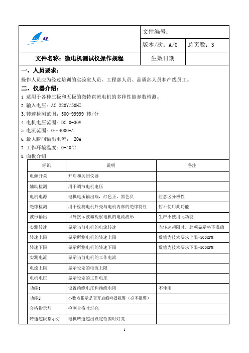
版本/次:A/0 总页数:3 文件名称:微电机测试仪操作规程生效日期
一、人员要求:
操作人员应为经过培训的实验室人员、工程部人员、品质部人员和产线员工。
二、仪器介绍:
1.适用于各种三极和五极的微特直流电机的多种性能参数检测。
2.输入电压:AC 220V/50HZ
3.转速检测范围:500-99999 转/分
4.电机电压范围:DC 0-30V
5.电流范围:0~4000mA
6.最大瞬间输出电流: 20A
7.工作环境温度:0-40℃
8.面板介绍
标识说明备注电源开关开启和关闭仪器
辅助检测用于调节电机电压
电机电源电机电压输出端,红色正,黑色负注意区分极性
绝缘检测用于检测电机外壳与电机内部的绝缘特性暂不使用此功能
波形输出可外接示波器观察电机的电流波形生产不使用此功能
实测转速显示当前电机的电流转速当转速超限时,此项显示将不准确转速上限显示所测电机的转速上限数值为技术要求上限+500RPM 转速下限显示所测电机的转速下限数值为技术要求下限-500RPM 实测电流显示当前电机的工作电流
电流上限显示设定的电流上限
电机电压显示设定的工作电压
功能1 设置绝缘电压和绝缘电阻不使用
功能2 小数点指示是否开启蜂鸣器报警(亮不报警)
合格指示灯检测合格时灯亮
转速超限指示灯电机转速超出设定范围时灯亮。
微电流治疗仪使用操作流程及评分标准

微电流治疗仪使用操作流程及评分标准1. 简介微电流治疗仪是一种常用于物理治疗的设备,通过微弱的电流刺激人体组织,以促进血液循环、减轻疼痛、促进组织修复等效果。
2. 使用操作流程以下是微电流治疗仪的使用操作流程:步骤一:准备工作1. 确保治疗仪的电源已连接好,并处于正常工作状态。
2. 清洁和消毒治疗区域,以确保卫生和安全。
步骤二:准备患者1. 将患者安置在舒适的位置上,并确保其身体部位暴露于治疗区域。
2. 告知患者治疗过程的目的、方法和可能的感受,以获得其合作。
步骤三:设置治疗参数1. 根据患者的情况,选择适当的治疗模式和参数。
2. 设置治疗时间和强度,根据医生的建议或根据治疗仪的说明书进行设定。
步骤四:开始治疗1. 将治疗仪的电极贴片或导电垫片正确放置在患者需要治疗的部位上。
2. 打开治疗仪的电源,并开始治疗。
确保电流的强度适中,以免给患者造成不适或伤害。
步骤五:监测和调整1. 在治疗过程中,密切观察患者的反应和感受。
2. 如有需要,根据患者的反应进行治疗参数的调整,以达到最佳的治疗效果。
步骤六:结束治疗1. 在治疗时间结束后,关闭治疗仪的电源。
2. 清理和消毒治疗区域,以维护卫生和安全。
3. 评分标准为了评估微电流治疗的效果,可以采用以下评分标准进行评价:疼痛缓解通过对患者的疼痛感受进行评分,评估治疗前后的疼痛缓解程度。
功能改善评估患者在治疗后的功能恢复情况,例如关节活动度、肌肉力量等指标的改善。
满意度通过患者对治疗效果和体验的主观评价,评估患者的满意度。
不良反应记录患者在治疗过程中出现的不良反应,如过敏、皮肤红肿等情况。
以上是微电流治疗仪的使用操作流程及评分标准。
在操作治疗仪时,请严格按照说明书和医生的建议进行操作,以确保治疗效果和患者的安全。
第十章 小电流电阻测试仪使用说明
1、简介
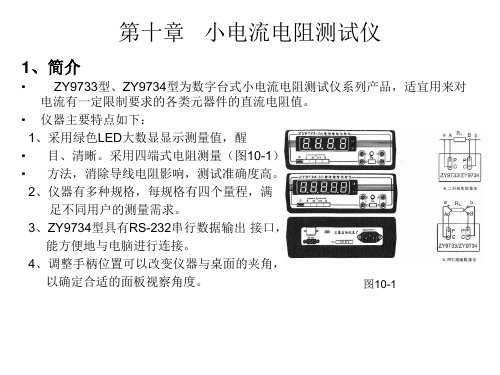
• ZY9733型、ZY9734型为数字台式小电流电阻测试仪系列产品,适宜用来对 电流有一定限制要求的各类元器件的直流电阻值。 • 仪器主要特点如下: 1、采用绿色LED大数显显示测量值,醒 • 目、清晰。采用四端式电阻测量(图10-1) • 方法,消除导线电阻影响,测试准确度高。 2、仪器有多种规格,每规格有四个量程,满 足不同用户的测量需求。 3、ZY9734型具有RS-232串行数据输出 接口, 能方便地与电脑进行连接。 4、调整手柄位置可以改变仪器与桌面的夹角, 以确定合适的面板视察角度。 图10-1
3、注意事项
① 仪器所附四线制测量导线,可消除引线电阻和接触电阻对测量结果带来的影响。 如果使用者改用自备的测量导线及测量夹具,则必须采用正确的四端测量夹 具,则必须采用正确的四端钮接线法,以保证测试精度。 ② 带电感电阻的测量过程中,不得随意移动、改接甚至卸下测量线夹,也 不得切换量程开关,以防电感中电流突变产生反电动势,损坏仪器。 测量中途若要实施上述操作,则必须先按下R0按钮或者关掉电源,等 电感放电后才能进行这些操作。 ③ 严禁市电或其他电流、电压源从测量端直接输入仪器,更不允许带电 测量。 ④ 严防静电或设备漏电损坏仪器:若被测对象在测量前做过耐压试验而 未经放电,或设备运转中产生高压静电,或设备漏电但外壳接地不可 靠甚至未接地等等,其静电高压或漏电高压会使仪器造成永久损坏。 表现为开路不出0、数字乱跳或测量误差大等等。为防止类似故障发 生,使用者应检查并消除静电及设备漏电。设备以及电源插座的接地 端必须与大地可靠连接。对于测量仪器,测量导线的C2端应与大地可 靠接线。
2、使用方法
(1) 面板视角调整:将手柄拉出,垂直于外壳底部移动到所需的凹槽处,再将手 柄向前推下即可。 (2) 开机预热:用随机所附四端式带线夹得测量导线与仪器正确相连。插上电源 • 线,按下合适的量程开关和输入短路R0按钮,按下“①”电源开关,仪器显 示 • 全0,预热30分钟。 (3) 调零:ZY9733型无调零装置,ZY9734型 测量前应在该档位进行调零,将测 量导线的线夹同向对接并将输入短路按钮R0复位后,调节调零电位器,使显 示器示值全为0。分开线夹,测量端开 路,显示器显示开路标志,其中 ZY9733型为C000,ZY9734型为C0000。 (4) 测量程序:先输入合适的量程开关,在输入短路按钮R0按下的前提下将测量 • 导线夹与被测电阻正确相连接。将输入短路按钮R0复位,仪器立即对被测电 • 阻进行测量,LED数码管便显示测量值。当被测值超出量程是,ZY9733型 • 显示1XXX(X表示数码管不亮),ZY9734型则显示闪烁的0000,表示溢出,此 • 时应该改用较高量程。当被测阻值过大甚至开路,则显示开路标志。
【产品手册】JY6701电容电流测试仪使用手册word资料11页
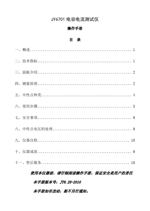
JY6701电容电流测试仪操作手册目录一、概述 (1)二、技术指标 (1)三、面板介绍 (2)四、测量原理 (2)五、中性点种类 (4)六、使用步骤 (5)七、安全事项 (9)八、中性点电压的处理 (9)九、仪器自检 (10)十、仪器成套 (9)十一、售后服务 (10)使用本仪器前,请仔细阅读操作手册,保证安全是用户的责任本手册版本号:JY6.28-2010本手册如有改动,恕不另行通知。
全自动电容电流测试仪一、概述我国的电力规程规定当10kV和35kV系统电容电流分别大于30A和10A时,应装设消弧线圈以补偿电容电流,这就要求对配网电容电流进行测量以做决定。
另外,配电网的对地电容和PT的参数配合会产生PT铁磁谐振过电压,为了验证该配电系统是否会发生PT谐振及发生什么性质的谐振,也必须准确测量配电网的对地电容值。
测量配网电容电流的方法有单相金属接地的直接法、外加电容间接测量法以及在PT开口三角形加异频信号等方法,但是,在现场最受欢迎和使用较频繁的还是使用中性点电容法。
本型号电容电流测试仪,采用中性点电容法原理测量配网的电容电流。
在做好安全措施后,在接触中性点前,先设置系统参数,然后则无需触碰操作仪器,使这项工作变得安全、简单且测试结果准确、可靠,不受其他运行条件影响,特别是系统不平衡的时候。
二、技术指标1、测量范围:对地总电容≤120μF(三相对地);电容电流≤100 A(35kv系统)电容电流≤200 A(6、10kv系统)2、测量精度:±5% (0.5μF<电容容量≤90μF);±10%(90μF<电容容量≤120μF)3、环境温度:-10~50℃;4、相对湿度:≤90%;5、工作电源:AC 220V ± 10% 50 Hz ± 1%;6、外形尺寸:320×200×150 mm;7、仪器重量:5 kg。
三、面板介绍图 1 仪器正面图 2 仪器侧面1:接地端2:打印机:打印测量数据和波形3:液晶屏4:中性点:通过电缆引致绝缘棒与变压器中性点相接触,测量位移电压信号。
微微流量计操作手册说明书
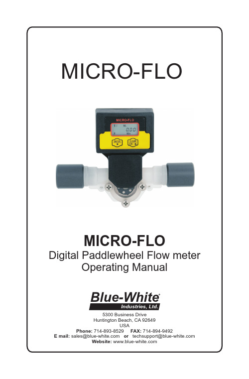
MICRO-FLODigital Paddlewheel Flow meterOperating Manual5300 Business Drive Huntington Beach, CA 92649USAPhone: 714-893-8529 FAX: 714-894-9492E mail:********************or **************************Website: Blue-WhiteIndustries, Ltd.MICRO-FLOPage 21.0IntroductionThe Micro-Flo flowmeter is designed to display flow rate and flow total on a six digit LCD display. The meter can measure bi-directional flows in either vertical or horizontal mounting orientation. Six flow ranges and four optional pipe and tubing connections are available. Pre-programmedcalibration K-factors can be selected for the corresponding flow range or a custom field calibration can be performed for higher accuracy at a specific flow rate. The meter is factory programmed for the correct K-factor ofthe body size included with the meter.TABLE OF CONTENTS1.....Introduction ....................................................................................22.....Features ..........................................................................................33.....Model number matrix ....................................................................34.....Specifications . (4)4.1..Temperature and pressure limits................................................44.2..Dimensions...............................................................................54.3..Replacement parts.....................................................................55.....Installation .. (6)5.1..Wiring connections...................................................................65.2..Circuit board connections.........................................................65.3..Flow verification output signal..................................................65.4..Panel or wall mountings............................................................76.....Operation . (7)6.1..Theory of operation...................................................................76.2..Control panel............................................................................86.3..Flow stream requirements.........................................................86.4..Run mode display......................................................................86.5..Run mode operation..................................................................96.6..Viewing the K-factor.................................................................97.....Programming . (9)7.1..Field Calibration.......................................................................97.2..Programming for body size/range S1 - S6.................................107.3..Field calibration range setting S0..............................................11Warranty information .. (12)2.0Features!Four connection options available:1/8” F/NPT, 1/4” F/NPT, 1/4” OD x .170 ID Tubing & 3/8” OD x 1/4” ID Tubing sizes.!Six body size/flow range options available:30 to 300 ml/min, 100 to 1000 ml/min, 200 to 2000 ml/min, 300 to 3000 ml/min, 500 to 5000 ml/min, 700 to 7000 ml/min.!3 model display variations:FS = Sensor mounted displayFP = Panel mounted display (includes 6’ cable)FV = No display. Sensor only. 5vdc current sinking output !6 digit LCD, up to 4 decimal positions.!Displays both rate of flow and total accumulated flow.!Open collector alarm setpoint.!User selectable or custom programmable K-factor. Flow units: Gallons, Liters, Ounces, milliliters Time units: Minutes, Hours, Days!V olumetric field calibration programming system.!Non-volatile programming and accumulated flow memory.!Total reset function can be disabled.!Clear PVC viewing lens or PVDF chemical resistant lens.!Weather resistant Valox PBT enclosure. NEMA 4XPage 3MICRO-FLOMETER FUNCTIONFS = Flow rate and Totalizing. On-sensor mounting FP = Flow rate and Totalizing. Remote panel mounting FV = Flow sensor only (no display)POWER SUPPLY1 = Transformer U.S. 115VAC/15VDC2 = Transformer E.U. 220VAC/15VDC3 = Transformer U.S. 230VAC/15VDC None = No selection (customer supplied)FLOW RANGE SELECTION10 = 30-300 ml/min 20 = 100-1000 ml/min 30 = 200-2000 ml/min 40 = 300-3000 ml/min 50 = 500-5000 ml/min 60 = 700-7000 ml/minO-RING SEALV = Viton E = EPDMCONNECTOR4 = .250” OD tubing PVDF5 = .125” Female NPT PVC6 = .375” OD tubing PVDF7 = .250” Female NPT PVCLENS MATERIAL0 = Clear PVC 1 = Opaque PVDF3.0 Model number matrix4.0SpecificationsMax. Working Pressure: o o PVC lens, 130 psig (9 bar) @ 70 F (21 C) o o PVDF lens,150 psig (10 bar) @ 70 F (21 C) Max. Fluid Temperature: o o PVC lens, F/NPT connectors 130 F (54 C) @ 0 PSI o o PVDF lens, tubing connectors 200 F (93 C) @ 0 PSI Full scale accuracy+/- 6%Input Power requirement: 9 - 28 VDC (31mA @ 15Vdc)Sensor only output cable: 3-wire shielded cable, 6ftPulse output signal:Digital square wave (2-wire) 25ft max.V oltage high = 5Vdc, V oltage low < .25Vdc 50% duty cycle Output frequency range: 4 to 500HzAlarm output signal:NPN Open collector. Active low aboveprogrammable rate set point.30Vdc maximum, 50mA max load.Active low < .25Vdc2K ohm pull up resistor required.Enclosure:NEMA type 4X, (IP56)Approximate shipping wt:1 lb. (.45 kg)MICRO-FLOPage 4Maximum Temperature vs. Pressure30(2)60(4)90(6)120(8)150(10)STATIC PRESSURE PSI (BAR)o o70F (21C)o o 96F (36C)o o 122F (50o o148F (64o o 200F (93C)T E M P E R A T U R Eo o174F (79C)4.1 Temperature and Pressure limits12345678219101415131920161718228PARTS LIST Key Part No. Description Qty.1 90011-081 Screw 6-32x.50 Phil Flt SS 4290002-227 Lens Cap Clear PVC 190002-228 Lens Cap Opaque PVDF 3 90003-143 O-Ring Viton 190003-146O-Ring EP 4 90002-230 Paddle PVDF 15 90007-592 Axle PVDF 16 90003-012 O-Ring Viton 290003-011 O-Ring EP776001-300 Body S1 PVDF (30-300ml/min)176001-301 Body S2 PVDF(100-1000ml/min)76001-302 Body S3 PVDF (200-2000ml/min)76001-303 Body S4 PVDF (300-3000ml/min)76001-304 Body S5 PVDF (500-5000ml/min)76001-305 Body S6 PVDF (700-7000ml/min)8 90011-113 Screw #4x.50 Phil Blk 4976000-137 Adapter .250 F/NPT PVC 276000-456Adapter .125 F/NPT PVC90002-038 Adapter .37OD x .25ID Tube PVDF 90002-042 Adapter .25OD x .17ID Tube PVDF 10 90012-252 Sensor 113 90002-242 Enclosure, Valox 114 90012-254 LCD display 115 90010-260 Circuit board 116 90006-604 Gasket, rear enclosure 117 90002-243 Cover, enclosure rear 118 90008-199 Liquid Tight Connector Set 119 90011-178 Screw #4x.62 Phil SS Blk 420 90011-177 Screw #2x.25 L Phil St 221 76001-299 Tubing connector seal 12290006-605Gasket, sensor mount seal 1Page 5MICRO-FLO5.00 in [127 mm]3.51 in [89.03 mm]1.48 in [37.71 mm]2.22 in [56.26 mm]4.2 Dimensions4.3 Replacement PartsMICRO-FLO Page 65.0 Installation5.1 Wiring ConnectionsOn sensor mounted units, the output signal wires must be installed through the back panel using a second liquid-tite connector (included). To install the connector, remove the circular knock-out. Trim the edge if required. Install the extra liquid-tite connector.On panel or wall mounted units, wiring may be installed through the enclosure bottom or through the back panel. See below.ribbon cable connection30 VDC max50mA max50% duty cycle5.3 Flow Verification Output SignalWhen connected to external equipment such as a PLC, data logger, or Blue-White metering pump, the pulse output signal can be used as a flow verification signal. When used with Blue-White metering pumps, connect the positive (+) terminal on the Micro-Flow circuit board to the pump’s yellow signal input wire and the negative (-) terminal to the black input wire.5.2 Circuit Board ConnectionsPage 7MICRO-FLOWiring through enclosure mounting screw locations1.00 in [25 mm]1.75 in [45 mm]Recommended panel or wall mounting cut-outfor wire connection opening5.4 Panel or wall mounting6.0Operation6.1 Theory of operationThe Micro-Flo flowmeter is designed to measure the flow rate and accumu-late the total volume of a fluid. The unit contains a paddle wheel that has six (6) through holes to allow infrared light to pass through, a light-detecting circuit and a LCD-display electronic circuit.As fluid passes through the meter body, the paddle wheel spins. Each time the wheel rotates a DC square wave is output from the sensor. There are six (6) compete DC cycles induced for every revolution of the paddle wheel. The frequency of this signal is proportional to the velocity of the fluid in the conduit. The generated signal is then sent into the electronic circuit to be processed.The meter is factory programmed for the correct K-factor of the body size included with the meter.The Micro-flo flowmeter includes the following features:!Displays either the flow rate or the accumulated total flow.!Provides a pulse output signal that is proportional to the flow rate.!Provides an open collector alarm output signal. Active low at flow rates above the user programmed value.!Provides user selectable, factory preset calibration k-factors.!Provides a field calibration procedure for more precise measurement. !Front panel programming can be disabled by a circuit board jumper pin.6.2 Control PanelEnter Button (right arrow) -!Press and release - Toggle between Rate, Total, and Calibrate screens in the run mode. Select program screens in the program mode.!Press and hold 2 seconds - Enter and exit program mode. (Automatic exit program mode after 30 seconds of no inputs).MICRO-FLOPage 86.4Run mode display6.5Run mode operationFLOW RATE DISPLAY - Indicates rate of flow, S1= body size/range #1, ML = units displayed in milliliters, MIN = time units in minutes, R = flow rate displayed.FLOW TOTAL DISPLAY - Indicates accumulated total flow, S1 = body size/range #1, ML = units displayed in milliliters, T = total accumulated flow displayed.T = Flow total indicatedHr = Rate per hour Day = Rate per daySetP (flashing) = alarm none = not programmedClear/Cal (up arrow) -!Press and release - Clear total in the run mode. Scroll through and Select options in the program mode.6.3 Flow stream requirements!The Micro-flo flowmeter can measure fluid flow in either direction.!The meter must be mounted so that the paddle axle is in a horizontal o position - up to 10 off the horizontal is acceptable.!The fluid must be capable of passing infra-red light.!The fluid must be free of debris. A 150 micron filter is recommended - especially when using the smallest body size (S1), which has a 0.031” through hole.Page 9MICRO-FLO7.0ProgrammingThe Micro-Flo flowmeter uses a K-factor to calculate the flow rate and total. The K-factor is defined as the number of pulses generated by thepaddle per volume of fluid flow. Each of the six different body sizes have different operating flow ranges and different K-factors. The meter is factory programmed for the correct K-factor of the body size included with the meter.The meter’s rate and total displays can be independently programmed to display units in milliliters (ML), ounces (OZ), gallons (GAL), or liters (LIT). Rate and total can be displayed in different units of measure. The factory programming is in milliliters (ML).The meter’s rate display can be independently programmed to display time base units in minutes (Min), Hours (Hr), or Days (Day). The factory programming is in minutes (Min).For greater accuracy at a specific flow rate, the meter can be field cali-brated. This procedure will automatically over-ride the factory K-factor with the number of pulses accumulated during the calibration procedure. The factory default settings can be re-selected at any time.7.1 Field CalibrationAny body size/range can be field calibrated. Calibration will take into account your specific application’s fluid properties, such as viscosity and flow rate, and increase the accuracy of the meter in your application.The Body Size/Range must be set for “S0” to enable the calibration mode. Follow the programming instructions on pages 10 & 11 to reset the BodySize/Range and perform the calibration procedure.to display the K-factor.6.6Viewing the K-factor (pulses per unit)to return to run mode.Useful formulas 60 / K = rate scale factorrate scale factor x Hz = flow rate in volume per minute1 / K = total scale factor total scale factor x n pulses = total volumeMICRO-FLOPage 107.2Programming for body size/ranges S1through S6 -Press and Hold ENTER to initiate the programming mode.> LITS4 > S5 > 6 > S0S 0.000 > 0.0000> LIT0.000 > 0.00000.0 > 0.00 > 0.000MICRO-FLOPage 11 7.3Field calibration size/range setting S0 - Continuation of programmingsequence when range “S0” is selected.The meter should be installed as intended in the application. Array The amount of fluid that flows through the meter during the calibrationprocedure must be measured at the end of the calibration procedure.Allow the meter to operate normally, in the intended application, for a period of time. A test time of at least one minute is recommended. Note - the maximum number of pulses possible is 52,000. Pulses will accumulate in the display. After the test time period, Stop the flow through the meter. The pulse counter willstop.Determine the amount of fluid that passed through the meter using a graduatedcylinder, scale, or other method. The measured amount must be entered incalibration screen #4 “MEASURED VALUE INPUT.”0.00 ># 80000-406Rev. 2/28/20085300 Business DriveHuntington Beach, CA 92649USAPhone: 714-893-8529 FAX: 714-894-9492E mail:********************or **************************Website: Blue-WhiteBLUE-WHITE INDUSTRIES LIMITED WARRANTYFLOWMETERS are warranted to be free of defects in material and workmanship for up to 12 months from the date of factory shipment. Warranty coverage is limited to repair or replacement of the defective flowmeter only. Blue-WhiteIndustries does not assume responsibility for any other damage that may occur. This warranty does not cover damage to the flowmeter that results from misuse or alterations, nor damage that occurs as a result of: meter misalignment,improper installation, over tightening, use of non- recommended chemicals, use of non-reccomended adhesives or pipe dopes, excessive heat or pressure, or allowing the meter to support the weight of related piping. Flowmeters are tested and calibrated with water and air only. Although meters may be suitable for other chemicals, Blue-White cannot guarantee their suitability.Flowmeters are repaired at the factory only. Call or write the factory to receive a Return Material Authorization number, carefully pack the flowmeter to bereturned, including a brief description of the problem. Note the RMA number on the outside of the carton.Prepay all shipping costs. The factory does not accept COD Shipments. Damagethat occurs during shipping is the responsibility of the sender.Users of electrical and electronic equipment (EEE) with the WEEE marking per Annex IV of the WEEE Directive must not dispose of end of life EEE as unsorted municipal waste, butuse the collection framework available to them for the return, recycle, recovery of WEEEand minimize any potential effects of EEE on the environment and human health due to the presence of hazardous substances. The WEEE marking applies only to countries within the European Union (EU) and Norway. Appliances are labeled in accordance with EuropeanDirective 2002/96/EC.Contact your local waste recovery agency for a Designated Collection Facility in your area.。
Clamp-on电流测量仪ischargeMercury800用户手册说明书
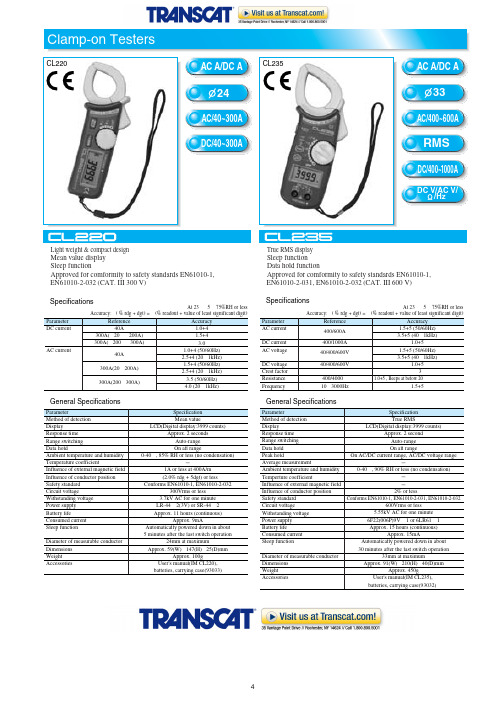
24mm at maximum Approx. 59(W)ʷ147(H)ʷ25(D)mm
Approx. 100g User's manual(IM CL220), batteries, carrying case(93033)
Clamp-on Testers
CL220
AC A/DC A CL235 24
AC/40~300A DC/40~300A
AC A/DC A
33
AC/400~600A RMS
DC/400~1000A
DC V/AC V/ /Hz
˔Light weight & compact design ˔Mean value display ˔Sleep function ˔Approved for comformity to safety standards EN61010-1,
Diameter of measurable conductor Dimensions Weight Accessories
Specification Mean value LCD(Digital display:3999 counts) Approx. 2 seconds Auto-range On all range 0-40ˆ, 85% RH or less (no condensation)
1A or less at 400A/m ʶ(2.0% rdg + 5dgt) or less Conforms EN61010-1, EN61010-2-032
dlro600大电流微欧计使用手册
最近,我接到了一项任务,那就是撰写一篇关于dlro600大电流微欧计的使用手册。
这是一项非常具有挑战性的工作,因为我需要以深度和广度的要求来全面评估这个主题,并据此撰写一篇有价值的文章。
1. 什么是dlro600大电流微欧计?dlro600大电流微欧计是一种用于测量电阻的仪器,特别适用于大电流测试的应用场景。
它具有高精度、高可靠性和高稳定性的特点,能够准确、快速地测量各种导体和接地系统的电阻值。
它广泛应用于电力、石油、化工、通信等行业的大电流测试领域。
2. 如何正确使用dlro600大电流微欧计?在使用dlro600大电流微欧计时,首先需要正确连接测试电缆和测量夹具,保证电路连接良好。
然后选择合适的测试电流和测试时间,进行测试操作。
在测试完成后,需要根据仪器显示的测试结果进行分析和记录,确保测试数据的准确性和可靠性。
3. 我对dlro600大电流微欧计的个人观点和理解作为一名专业的文章写手,我对dlro600大电流微欧计有着深刻的理解和认识。
我认为这款仪器不仅具有先进的技术和性能,而且在实际应用中能够带来显著的效益和价值。
它能够满足工程和项目对大电流测试的需求,为用户提供可靠、准确的测试数据,是一款非常实用的测试仪器。
4. 总结和回顾通过本文的全面阐述,相信读者已经对dlro600大电流微欧计有了更深入的了解。
在实际使用中,需要注意正确操作和维护,以确保仪器的性能和精度。
希望本文能够为大家在使用dlro600大电流微欧计时提供一些帮助和参考。
总结起来,我认为dlro600大电流微欧计是一款非常实用的测试仪器,具有广泛的应用领域和重要的意义。
希望本文能够帮助大家更加全面、深刻和灵活地理解这一主题。
dlro600大电流微欧计是目前市场上非常先进和实用的大电流测试仪器,它的出现为工程和项目测试带来了新的可能性和便利。
它不仅具有诸多优点,还有一些需要注意的地方,下面我们将从技术特点、正确使用、个人观点和建议等方面来续写扩写新内容。
电流测试仪的使用方法
电流测试仪是一种用来测量电流大小的仪器。
下面是使用电流测试仪的一般步骤:
1. 确保电流测试仪的电池或电源已经安装好,并且仪器处于工作状态。
2. 确保电路或设备处于关闭状态,以免发生电击或损坏仪器。
3. 将测试仪的测量端子正确连接到电路中的相应位置。
通常,红色的测试针连接到电路的正极,黑色的测试针连接到电路的负极。
4. 打开电路或设备,使电流开始流动。
5. 观察测试仪的显示屏或指针,读取电流的数值。
确保读取时注意单位,例如安培(A)或毫安(mA)。
6. 当测量完成后,关闭电路或设备,断开测试仪的连接。
7. 将电流测试仪的电源关闭,以节省电池或电源的使用。
需要注意的是,在使用电流测试仪时,应遵循相关的安全操作规程,避免触摸电路中的裸露导线或接触高电压部分,以免发生电击事故。
此外,对于较高电流的测量,可能需要使用额外的安全措施,如穿戴绝缘手套或使用安全电流钳等。
如果对使用电流测试仪的操作不熟悉,建议请专业人士进行操作或咨询。
- 1、下载文档前请自行甄别文档内容的完整性,平台不提供额外的编辑、内容补充、找答案等附加服务。
- 2、"仅部分预览"的文档,不可在线预览部分如存在完整性等问题,可反馈申请退款(可完整预览的文档不适用该条件!)。
- 3、如文档侵犯您的权益,请联系客服反馈,我们会尽快为您处理(人工客服工作时间:9:00-18:30)。
目录
一、 概述 (1)
二、 标准设备 (2)
三、 安全信息 (3)
四、 微电流测试仪概述 (4)
1、微电流测试仪按键 (4)
2、显示屏幕 (6)
五、 技术指标 (7)
1、测量范围 (7)
2、测量精度 (7)
3、供电电源 (7)
4、外形尺寸 (7)
5、测量方式 (7)
6、显示方式 (7)
7、测量端输入电压 (7)
8、每一档量程均可输出电压 (7)
9、响应时间 (7)
10、自动量程切换 (7)
11、自动量程切换时间 (7)
12、短路瞬间过载电压 (7)
13、使用环境 (7)
六、 测量模式 (8)
1、手动测量 (8)
2、自动测量 (8)
3、注意事项 (9)
4、输出电压 (9)
七、 微电流测试仪标定 (10)
八、 典型应用 (11)
一、概述
MK-1000微电流测试仪是针对各种工业现场的实际需求设计生产的,主要应用于静电、光电流、生物电流的测量。
具有体积小、质量可靠、精度高、稳定性好等特点, 深受广大客户的喜爱!
二、标准设备
标准设备包括以下列出的项目:
z MK-1000微电流测试仪一台
z电缆线一根
z电源线一根
z MK-1000微电流测试仪用户手册
z合格证
z保修卡
图1 MK-1000微电流测试仪外观图
电缆线
注意:
如果微电流测试仪有损坏或缺少某些附件,请立即与我们的销售人员或公司联系!
三、安全信息
使用MK-1000微电流测试仪之前,请仔细阅读本手册。
在充分理解的基础上,再对MK-1000微电流测试仪进行操作。
错误的使用会导致仪表损坏或人身伤害。
严禁对MK-1000微电流测试仪进行任何改造!由于擅自改造所造成的事故,本公司恕不负责。
注意:
1、切勿使用已损坏的微电流测试仪。
使用前应检查微电流测试仪的 外壳是否有断裂或缺少塑料元件。
特别要注意接头周围是否绝缘。
2、请遵循设备的安全步骤进行操作。
3、根据测量要求选择正确的功能和量程档。
四、微电流测试仪概述
1、微电流测试仪按键
图3为微电流测试仪正视图,图4为微电流测试仪背面图,各按键功能见表3。
图3 微电流测试仪正视图
图4微电流测试仪背面图
表3
按键名称 说明
测量输入端
手动量程选择测量和自动量程选择测量选择开
关
开机显示状态,开始显示0
测量的量程为0-±1nA
测量的量程0-±10nA
测量的量程0-±100nA
测量的量程0-±1μA
测量的量程0-±10μA
测量的量程0-±100μA
测量的量程0-±1mA
电源开关
2、显示屏幕
图4 典型显示屏幕
五、技术指标
1、测量范围:0-±1nA, 10nA, 100nA, 1uA, 10uA, 100uA, 1mA;
2、测量精度:±0.5%;
3、供电电源:85V-260V AC,功耗小于10W;
4、外形尺寸:240×120×220mm;
5、测量方式:手动量程选择测量方式和自动量程选择测量方式;
6、显示方式:4位数字显示0-1999;
7、测量端输入电压:< 1mV;
8、每一档量程均可输出电压:0-±1V /FS。
9、响应时间:1nA档 < 5秒,10nA以上档<1秒。
10、自动量程切换:当数字< 100或数字>1000时自动切换。
11、自动量程切换时间:<0.5秒;
12、短路瞬间过载电压:<30V/1秒
13、使用环境:温度18℃~25℃,湿度RH<50%
六、测量模式
1、手动测量模式
1)、将微电流测试仪的电源插头插到85V-260V AC。
2)、将电源开关拨到开的状态。
3)、将『手动』和『自动』选择开关拨到『手动』档,此时开机显示状态处在『0状态』。
4)、接上测量的电缆线,注意将屏蔽层(黑色表头)必须接信号地,红色表头接信号正极。
如果信号接反,将会引起测量结果不稳定,数值连续跳动。
5)、选择一个量程范围进行测量,如果发现屏幕显示超出范围一直在闪动,则表明您选择的量程范围偏小,应该重新选择量程大的范围进行测量。
6)、仪表读数时,根据屏幕显示的数值和您选择的量程范围进行读数:假如屏幕显示的数值为7.92,量程范围选择的是10nA,则实际数值就为7.92nA;假如屏幕显示的数值为7.92,量程范围选择的是10μA,则实际数值就为7.92μA。
2、自动测量模式
1)、将微电流测试仪的电源插头插到85V-260V AC。
2)、将电源开关拨到开的状态。
3)、将『手动』和『自动』选择开关拨到『自动』,仪表的量程将自动选择档,经过从左到右的跳动之后,最终开机显示状态处在
『1nA状态』。
(输入信号=0,开路)。
4)、接上测量的电缆线,注意将屏蔽层(黑色表头)必须接信号地,红色表头接信号正极。
如果信号接反,将会引起测量结果不稳定,数值连续跳动。
5)、当信号输入时,仪表根据输入信号的大小自动选择测量量程。
6)、仪表读数和手动测量模式读数相同。
3、注意事项
1、当使用小量程测量时信号易受干扰,注意屏蔽!
2、手动测量时,必须选择合适的量程,信号超量程时数字将闪动,信号太小,显示读数太少不够精确。
一般在〉100个数字,< 1200个数字之间。
4、输出电压:
1、在仪器的后板有二个插孔,测量时输出0-±1V的直流电压,内阻为1K。
七、微电流测试仪标定
测试仪在测试时发现测量结果与实际值有偏差,可以将仪表串联一台标准的电流表,再根据电流表的准确值进行调整。
具体的调整方法如下:
1)、将『手动』和『自动』选择开关拨到『手动』档。
2)、手动选择相应的量程(如10nA档有偏差)。
3)、连续按住此量程按钮约5秒,直到屏幕左边显示一个“P”字,即可放开。
4)、按住1mA档的按钮,数值增加。
5)、按住100μA档的按钮,数值减少。
6)、调整到标准值,调整完后,按下”0”的按钮,屏幕左边的“P”字消失,仪表自动保存修改值,断电不丢失。
7)、其他档的量程标定方法同上!
八、典型应用
1)测量防静电鞋、导电鞋的电阻值
2)测量防静电、导电材料的电阻及电阻率 3)测量计算机房用活动地板的系统电阻值 4)测量绝缘材料电阻(率)
5)光电二极管暗电流测量
6)物理,光学和材料研究
7)生物电流的测量。