laser test
laser 测量原理
laser 测量原理
激光测距(laser distance measuring)是以激光器作为光源进行测距。
根据激光工作的方式,可以分为连续激光器和脉冲激光器。
激光测距的原理主要是基于光速和时间的关系,通过测量光在空气中传播的时间来计算距离。
对于脉冲激光测距,测距仪发射出的激光经被测量物体的反射后又被测距仪接收,测距仪同时记录激光往返的时间。
光速和往返时间的乘积的一半,就是测距仪和被测量物体之间的距离。
脉冲法测量距离的精度一般是在±10厘米左右,而测量盲区一般是1米左右。
此外,还有相位式激光测距,主要使用连续输出的氦氖、氩离子、氪镉等气体激光器。
相位式激光测距的原理是利用激光器的频率稳定度和传播速度,通过测量相位差来计算距离。
相位式激光测距的精度较高,可以达到毫米级别,但测量范围较小。
以上内容仅供参考,如需获取更多信息,建议查阅关于激光测距的资料或者咨询专业人士。
HDI 生产Tooling简介
HDI生產Tooling簡介
Confidential
製作: 吳彩霞
日期:
2007
年2 Page:1
月
9鴻日勝 科 技 股 份 有 限 公 司
教學目的
A. 了解HDI Symbol之設計與目的 B. 了解HDI Tooling孔之設計與目的 C. 了解HDI Test Pattern之設計與目的 D. 了解HDI 其他製程控制輔助Tooling之設計與目的
SUMMARY of Via Chain & Registration:
Via Structure
Test Key
Via Chain
Registration
Plus I
A1 (L1-L2)
B1 (L1-L2)
Staggered Via
A3 (L1-L2 & L2-L3)
B1 (L1-L2) B2 (L2-L3)
2. Tooling孔—PCB製造過程中,機台需要固定板材及對位加工時,於板材上所製 作出之特殊孔。 例如:鉚釘孔、組合孔、曝光對位孔等
3. Test Pattern—PCB產品上用來監控通盲層間對位,訊號及信賴度品質之特殊配 線設計區塊。
例如:同心圓 、Copper Peel Strength、Laser Test Key等
LPR 底片定位 PIN孔Symbol
靶孔 Symbol
Symbol介紹 (以1+6+1為例)
個數
6
Symbol層別
基板層別 / L3,4,5,6
位置同LPR鉚合孔
附註
2 基板層別 / L3,4,5,6
位置同LPR組合孔
激光损伤阈值测试
激光损伤阈值测试Laser Damage Threshold TestingLaser Damage Threshold (LDT) is one of the most importantspecifications to consider when integrating an optical component intoa laser system. Using a laser in an application offers a variety ofbenefits to a standard light source, including monochromaticity,directionality, and coherence. Laser beams often contain high energies, though, and are capable of damaging sensitive optical components.When integrating a laser into an optical system, it becomes crucial tounderstand the effects of laser beams on optical surfaces and how laser damage threshold is quantified for optical components.The degree of damage induced to an optical component by a laser beam is highly dependent on the type of laser being used. Thermally-induced damage occurs under Continuous Wave (CW) laser operation. During exposure to the CW laser, the optical material may not have sufficient time to thermally relax, and failure can occur due to thermal damage to the bulk material or the optical coating. Alternatively, the damage caused by a short, intense laser pulse is due to ionization: the breakdown of the molecular bond. The electric field generated by the laser beam at the optical surface stimulates electrons at the outer energy band, causing ionization. However, it is important to keep in mind that lasers with long pulse widths (<10s) or high repetition rates(>10MHz) may also cause thermally induced damage. For these reasons, understanding laser damage threshold is crucial to designing and maintaining an optical system. -6T esting Laser Damage ThresholdLaser-induced damage threshold testing is a good method for quantifying the amount of electromagnetic radiation an optical component can withstand. There are a variety of different LDT tests. For example, Edmund Optics follows the ISO-11254 procedures and methods, which is the industry standard for determining the laser damage threshold of an optical component. Utilizing the ISO-11254 standard enables the fair comparison between optical components from different manufacturers.Edmund Optics' LDT testing is conducted by irradiating a number of test sites with a laser beam atdifferent energy densities for pulsed lasers, or different power densities for CW lasers. The energy density or power density is incrementally increased at a minimum of ten sites at each increment. The process is repeated until damage is observed in 100% of the irradiated sites. The LDT is the highest energy or power level at which no damage is observed in any of the irradiated sites. Inspection of the sites is done with a Nomarski-type Differential Interference Contrast (DIC) microscope with 100X - 150X magnification. Visible damage is observed and the results are recorded using pass/fail criteria. Figure 1 is a typical damage probability plot of exposure sites as a function of laserpulse energy.In addition to uncoated optical components, optical coatings are also subject to damage from the presence of absorption sites and plasma burn. Figure 2 is a real-world image of coating failure due to a coating defect. For additional information on the importance of LDT testing on coatings, view The Complexities of High-Power Optical Coatings.Figure 1:Exposure Histogram of Laser Damage Threshold Probability versus Exposure SiteFigure 2: Coating Failure from 73.3 J/cm3 Source due to Coating DefectDefining Laser Damage ThresholdThere are many variables that affect the Laser Damage Threshold (LDT) of an optical component. These variables can be separated into three categories: laser, substrate, and optical coating (Table 1).LDT is typically quantified with units of power or energy densities for CW and pulsed lasers, respectively. Power density is the power per cross-sectional beam area. Similarly, energy density is the energy per cross-sectional beam area of a specific pulse duration. Lasers are available with a multitude of different wavelengths and pulse durations, therefore, it is important that the optical component's LDT is suitable for the laser's parameters. As a general rule of thumb, Newton's square root scaling factor can be used to determine whether a laser can be used with an optic that is not rated at thesame LDT pulse duration specification. Equation 1 calculates a new LDT for the different pulse duration.(1)The LDT(y) is the estimated LDT for laser Y, and LDT(x) is the specified LDT for laser x. τ is the pulse duration for laser y, and τ is the pulse durat ion for laser x. Additionally, since the energy of a photon is inversely proportional to its wavelength, then theoretically the LDT scales linearly as a function of wavelength, as expressed in Equation 2. yx(2)Where PD is the Power or Energy Density at the new wavelength, PD is the Power or Energy Density at the old wavelength, λ is the new wavelength, and λ is the old wavelength. A laser with a PD of 2 W/cm at 1064nm would have a power density of 1 W/cm at 532nm, 0.667 W/cm at 355nm, etc. (y)(x)yxCW222There are some drawbacks to the scaling, as there are non-linear effects associated with the conversion. However, they are a good rule of thumb for estimating the LDT of an optic at varying wavelengths and pulse durations. Note: Optical manufacturers only guarantee the specified LDT, not scaled estimations. Laser Damage Threshold (LDT) testing is crucial when working with laser optics. Understanding how LDT is tested and defined helps choose the right optical components for the application. Laser optics thatare designed with an LDT that is suitable for a given laser ensure superior results and product lifetime, and help avoid additional expenses due to damaged components.。
microscan 870中文简明设置
MENELAUS_ZMicroscan QX-870中文简明快速设置针对采集器主要参数详细说明硬件正确连接后,使用Microscan ESP5.0及以上版本设置QX-870相关参数。
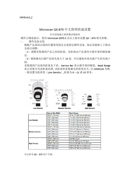
一.硬件设备安装根据产品条码出现的位置使用固定支架固定硬件设备,保证其能够上下移动及前后调整。
(1)调整采集器到产品之间的距离,该距离由产品条码中最窄条码精度确定。
(2)确保激光扫描产品的夹角大于15度,可以避免外部光源产生的光线干扰。
采集器到产品条码距离见下表。
Narrow Bar表示最窄条码精度,Read Range 表示采集可识读距离范围。
该距离和采集激光的密度有关。
以CODE128为例:一般设置为低密度(Low Density),距离为8-12或15厘米。
可以参考QX-870用户手册。
二.ESP调试软件说明。
1.双击“Microsoft ESP”软件,打开软件。
在弹出的硬件设备表中,选择QX-870,点击OK键。
提示是否连接,点击是按键。
下方红色DISCONNECTED表示未连接。
设置硬件所连接的端口及协议,可以不用选择直接点击Auto Connect。
自动连接匹配后提示连接成功。
进入ESP设置界面,下方状态栏显示绿色CONNECTED表未连接成功。
点击左上角App Mode进入菜单设置,并选择第二项Read Cycle。
各项参数说明如下:Multisymbol标签设置Number of Symbols:一次扫描条标签条码的个数。
Multisymbol Separator:指定各标签之间分隔符。
Trigger触发扫描模式Mode:Continuous Read连续读取;Countinous Read 1 Output连续读取只输出1个条码;External Level外部级别模式;External Edge外部边沿模式。
Level和External在读周期开始条件是相同的,但结束时间不一样。
Decodes Before Output输出前的译码Mode:Non-consecutive对识读的条码进行无序计数。
物理专业 词汇L
landau spectrum 朗道谱
landau zener theory 朗道 齐纳理论
lander 着陆七
landspout 陆龙卷
lang camera 兰氏照相机
lang's method 兰氏法
law of conservation of mass 质量守恒定律
law of conservation of momentum 动量守恒定律
law of indestructibility of matter 物质不灭定律
law of large numbers 大数定律
law of mass action 质量酌定律
large hadron collider 大型强子碰撞型加速装置
large scale fractal structure 大尺度分形结构
large scale integrated circuit 大规模集成电路
large scale magnetic field in galaxies 大尺度银河磁场
lanthanides 镧族稀土元素
lanthanum 镧
laplace integral 拉普拉斯积分
laplace transformation 拉普拉斯变换
laplace's demon 拉普拉斯妖
laplacian 拉普拉斯算符
laplacian equation 拉普拉斯方程
lambda particle 粒子
lambda point 点
lambda transition 跃迁
IPG高功率激光器开关机操作指南
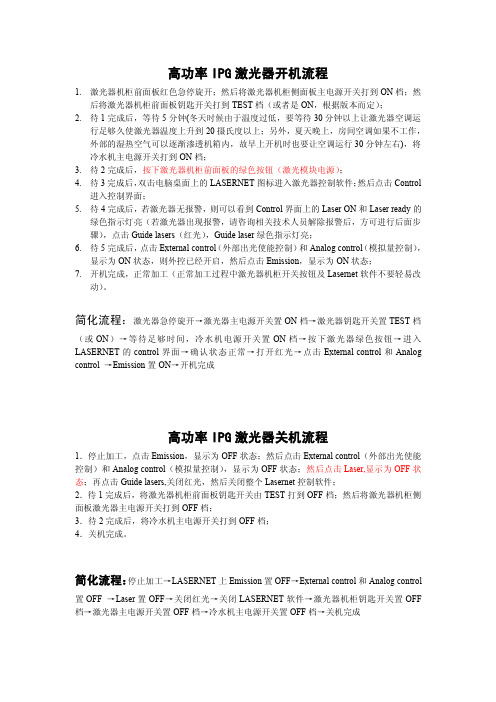
高功率IPG激光器开机流程1.激光器机柜前面板红色急停旋开;然后将激光器机柜侧面板主电源开关打到ON档;然后将激光器机柜前面板钥匙开关打到TEST档(或者是ON,根据版本而定);2.待1完成后,等待5分钟(冬天时候由于温度过低,要等待30分钟以上让激光器空调运行足够久使激光器温度上升到20摄氏度以上;另外,夏天晚上,房间空调如果不工作,外部的湿热空气可以逐渐渗透机箱内,故早上开机时也要让空调运行30分钟左右),将冷水机主电源开关打到ON档;3.待2完成后,按下激光器机柜前面板的绿色按钮(激光模块电源);4.待3完成后,双击电脑桌面上的LASERNET图标进入激光器控制软件;然后点击Control进入控制界面;5.待4完成后,若激光器无报警,则可以看到Control界面上的Laser ON和Laser ready的绿色指示灯亮(若激光器出现报警,请咨询相关技术人员解除报警后,方可进行后面步骤),点击Guide lasers(红光),Guide laser绿色指示灯亮;6.待5完成后,点击External control(外部出光使能控制)和Analog control(模拟量控制),显示为ON状态,则外控已经开启,然后点击Emission,显示为ON状态;7.开机完成,正常加工(正常加工过程中激光器机柜开关按钮及Lasernet软件不要轻易改动)。
简化流程:激光器急停旋开→激光器主电源开关置ON档→激光器钥匙开关置TEST档(或ON)→等待足够时间,冷水机电源开关置ON档→按下激光器绿色按钮→进入LASERNET的control界面→确认状态正常→打开红光→点击External control和Analog control→Emission置ON→开机完成高功率IPG激光器关机流程1.停止加工,点击Emission,显示为OFF状态;然后点击External control(外部出光使能控制)和Analog control(模拟量控制),显示为OFF状态;然后点击Laser,显示为OFF状态;再点击Guide lasers,关闭红光,然后关闭整个Lasernet控制软件;2.待1完成后,将激光器机柜前面板钥匙开关由TEST打到OFF档;然后将激光器机柜侧面板激光器主电源开关打到OFF档;3.待2完成后,将冷水机主电源开关打到OFF档;4.关机完成。
激光电源说明书
产品名称:二氧化碳激光电源主要型号:MYKZ40W MYJG40W MYJG60W MYJG80W MYJG130W主要特点:MYKZ40W MYJG40W MYJG60W MYJG80W MYJG130W系列高频二氧化碳激光电源是我公司与权威二氧化碳激光器制造企业共同研发成功的高效、高频、高速二氧化碳激光器配套电源,体积小、重量轻、操作方便,与激光器匹配度高。
可直接与激光器相连,省去了笨重、发热严重的镇流电阻。
此电源能够使二氧化碳激光器启辉容易,帮助二氧化碳激光器的性能得到充分发挥,提高转换效率,延长激光器的使用寿命。
主要技术参数:1.输入电压:AC220V,AC110V(订货时请特别说明)。
2.输出激光起辉电压:DC40KV(130W),DC35KV(W),DC30KV,DC26KV(40W)。
3.输出最大电流:DC38mA(130W),DC30mA(80W)DC24mA(60W)DC20mA(40W)。
4.响应速度:≤1mS。
5.TTL电平开关控制:有效电平可高、低选择。
6.保护开关:可用于水路的有无检测,保护激光器不受损害;或打开外壳时的保护等。
7.激光器功率调节:(1)由电位器调节激光电源的输出电流。
(2)由PWM(幅值为TTL电平)控制。
8.电源本身可带有反馈接口,可以用于闭环控制,用于检验激光器的实际工作电流。
9.使用环境:温度(-10~40)℃,湿度:≤85%。
10.外形尺寸:(1)KZ40W:165*145*90(mm)(2)JG40W:180*144*91(mm)(3)60W:207*144*91(mm);(4)80W:280*173*97(mm)(5)130W:350*243*97(mm)使用说明:1)与激光管的连接:激光电源的高压(HV+)必须与二氧化碳激光管的阳极(全反射端)相连。
激光电源的电流回路通过一个电流表(或直接)与二氧化碳激光管的阴极(激光输出端)相连。
2)控制信号线的连接:如图1(或图2),将控制信号线分别可靠接入激光电源的控制端。
光源特性测试实验
光源特性测试模块实验LD 的工作原理及结构认知1.激光器一般知识及工作原理激光器是使工作物质实现粒子数反转分布产生受激辐射, 再利用谐振腔的正反馈, 实现光放大而产生激光振荡的。
激光, 其英文LASER 就是Light Amplification by StimulatedEmission of Radiation (受激辐射的光放大)的缩写。
激光的本质是相干辐射与工作物质的原子相互作用的结果。
尽管实际原子的能级是非常复杂的, 但与产生激光直接相关的主要是两个能级, 设Eu 表示较高能级, El 表示较低能级。
原子能在高低能级间跃迁, 在没有外界影响时, 原子可自发的从高能级跃迁到低能级, 并伴随辐射一个频率为h E E l u /)(-=ν (式1) 的光子, 这过程称自发辐射。
若有能量为 的光子作用于原子, 会产生两个过程:一是原子吸收光子能量从低能级跃迁到高能级, 同时在低能级产生一个空穴, 称为受激跃迁或受激吸收, 此激发光子消失;二是原子在激发光子的刺激下, 从高能级跃迁到低能级, 并伴随辐射一个频率 h E E l u /)(-=ν (式2) 的光子, 这过程称受激辐射。
受激辐射激发光子不消失, 而产生新光子, 光子增加, 而且产生的新光子与激发光子具有相同的频率、相位和偏振态, 并沿相同的方向传播, 具有很好的相干性, 这正是我们所需要的。
受激辐射和受激吸收总是同时存在的, 如果受激吸收超过受激辐射, 则光子数的减少多于增加, 总的效果是入射光被衰减;反之, 如果受激辐射超过受激吸收, 则入射光被放大。
实现受激辐射超过受激吸收的关键是维持工作物质的原子粒子数反转分布。
所谓粒子数反转分布就是工作物质中处于高能级的原子多于处于低能级的原子。
所以原子的粒子数反转分布是产生激光的必要条件。
实现粒子数反转可以使受激辐射超过受激吸收, 光在工作介质中得到放大, 产生激光, 但工作介质的增益都不足够大, 若使光单次通过工作介质而要产生较强度的光, 就需要很长的工作物质, 实际上这是十分困难, 甚至是不可能的。
惠普激光打印机打印内部测试页的方法
惠普激光打印机打印内部测试页的方法HP LASERJET 4L和HP LASERJET 4ML 打印机∙确认打印机的“就绪”指示灯亮着。
∙暂时地按打印机的前面板按钮(不要将其按下)。
∙大约六秒钟之后,“数据”指示灯就会亮起来,“就绪”指示灯将闪烁,然后将打印“自测”页。
注:HP LASERJET 4ML 打印机的“自测”页程序实际上会生成多个涉及“配置/类型页”的页面---包括其他信息页。
有关其他信息,请参阅HP LASERJET ET 4ML用户手册的5-7页。
HP LASERJET 4P和HP LASERJET 4MP打印机∙按下打印机的ON LTNE 按钮以使打印机脱机。
00 OFFLINE 出现在显示屏上。
∙反复按MENU,直至TEST MENU出现在打印机的显示屏上。
按ITEM,∙SELF TEST将出现在显示屏上。
∙按ENTER 键,∙05 SELF TEST 将出现在显示屏上几秒钟,然后当“PCL配置”页开始打印时将出现06 PRINTING TEST。
∙打印了该页之后,按下ON LINE 以使打印机恢复联机状态。
HP LASERJET 4和HP LASERJET 4M打印机∙按下打印机的NO LINE 按钮以使打印机脱机。
∙按住控制面板上的MENU按钮,直至TEST MENU出现在显示屏上。
∙按住ITEM,直至SELF TEST 出现在显示屏上。
∙按ENTER 键,∙将开始进行自测打印。
∙按下ON LINE 以使打印机恢复联机状态。
HP LASERJET 4 PLUS 和HP LASERJET 4M PLUS 打印机∙按下打印机的ON LINE 按钮以使打印机脱机。
∙按住控制面板上的MENU按钮,直至TEST MENU 出现在显示屏上。
∙按住ITEM,直至SELF TEST 出现在显示屏上。
∙按ENTER键,∙将开始进行自测打印。
∙按下ON LINE以使打印机恢复联机状态。
HP LASERJET 5L 打印机∙确信“就绪”(底部)指示灯亮着且其他所有的LED 都未亮,∙如果打印机处于“休眠”模式,请按下前面板按钮以使其进入“就绪”状态。
激光测试技术 原理(二)
激光测试技术原理(二)激光测试技术原理1. 激光的基本原理•激光(laser)是一种高度集中和定向的光束,其产生原理是基于激光器中的受激辐射。
•激光器由三个基本组件组成:工作物质、泵浦源和光学谐振腔。
•工作物质可以是固体、气体或液体,泵浦源向工作物质提供能量,光学谐振腔保持光波的相干性。
2. 激光测试的原理•激光测试技术利用激光束对被测物体进行扫描和测量,以获取关于物体特征和性质的信息。
•激光束可以通过光学透镜和反射镜进行聚焦和导向,使其经过被测物体并接收反射回来的光信号。
•接收的光信号经过光电转换后,就可以利用相应的信号处理和分析技术,获取被测物体的相关数据。
3. 激光测试的应用领域•激光测试技术在各个领域都具有广泛的应用。
•在制造业中,激光测试可以用于测量零件尺寸、检测表面缺陷,并对产品质量进行评估。
•在医学领域,激光测试可以用于激光成像、激光治疗和激光手术等应用。
•在环境监测中,激光测试可以用于大气污染物的检测、水质分析和地球观测等方面。
•在科学研究中,激光测试可以用于光谱分析、发射光谱测量和激光光谱学等研究。
4. 激光测试技术的发展趋势•随着科技的发展,激光测试技术也在不断演进。
•近年来,随着激光器的小型化和便携化,激光测试设备越来越普及和易用。
•同时,激光测试技术的精度和灵敏度也在不断提高,可以满足更多复杂和高精度测量的需求。
•未来,激光测试技术有望在汽车、航天、无人机等领域得到更广泛的应用,并为行业的发展提供支持。
结论通过本文的简要介绍,可以看出激光测试技术在不同领域具备广泛的应用前景。
随着技术的不断进步,相信激光测试技术将为各行各业带来更多的创新和发展机会。
让我们拭目以待,见证激光测试技术的未来!。
- 1、下载文档前请自行甄别文档内容的完整性,平台不提供额外的编辑、内容补充、找答案等附加服务。
- 2、"仅部分预览"的文档,不可在线预览部分如存在完整性等问题,可反馈申请退款(可完整预览的文档不适用该条件!)。
- 3、如文档侵犯您的权益,请联系客服反馈,我们会尽快为您处理(人工客服工作时间:9:00-18:30)。
Key Words: Impeller flow; two-dimensional; laser velocimeter
INTRODUCTION
of Computational Fluid Dynamics (CFD) computer codes for complex turbomachinery affords three-dimensional (3-D) flow field calculations. However, existing data for pump CFD code validation is limited. Accurate databases are required to validate the CFD codes to enable evaluation of existing turbulence models and grid number requirements. Traditional flow field survey information from pressure sensors and directional probes are intrusive and typically yield an uncertainty in excess of 0.5% of full range and thus do not yield quality benchmark data. Pressure sensors and directional probes only yieldcircumferentially averaged information. Laser velocimetry is nonintrusive and yields accurate flow velocity and angle data. More importantly, laser velocimetry provides information at specific circumferential locations blade to
evelopment
The tested configuration consisted of a four-bladed unshrouded inducer, a shrouded impeller with six full blades and six partial blades, in conjunction with a diffusing crossover and discharge plenum. The flow field survey consisted of 10 radial stations along one axial plane at the impeller inlet, 11 axial stations in a radial plane immediately downstream of the impeller discharge, and 9 axial stations close to the crossover inlet. The fluid medium for the laser velocimeter surveys was ambient water. Data are nondimensionalized as follows: Nondimensional Length:
L. A. BROZOWSKI, T. V. FERGUSON and L. ROJAS
Rockwell International Corporation, Rocketdyne Division, Canoga Park, California
(Received August 9, 1995)
Development of Computational Fluid Dynamics (CFD) computer codes for complex turbomachinery affords a complete three-dimensional (3-D) flow field description. While significant improvements in CFD have been made due to improvements in computers, numerical algorithms, and physical modeling, a limited experimental database for pump CFD
TEST FACILITY
The test program was conducted in the Engineering Development Laboratory (EDL) Pump Test Facility (PTF) located at Rocketdyne’s main facility in Canoga Park, California. A schematic of the flow loop is presented in Figure 3. The test article was driven by a 1,200-rpm, reversible, synchronous electric motor rated at 2,984 kW. The motor was coupled to a 2,984-kW gearbox capable of producing speeds of 6,322, 8,013, and 10,029 rpm. The pump CFD code validation configuration was tested at 6,322 rpm. Water was supplied to the closed flow loop from a 28.769-m stainless steel tank. The tank was rated at 1.0342 MPa with a vacuum capability of 0.0962 MPa. A heat exchanger located adjacent to the tank maintained a uniform fluid inlet temperature. The flow rate to the tester was regulated by a throttle valve downstream of the pump. After passing through the throttle valve and into the tank, the flow passed through a series of baffles in the tank and was recirculated through the facility.
International Journal of Rotating Machinery 1996, Vol. 2, No. 3, pp. 149-159 Reprints available directly from the publisher Photocopying permitted by license only
code validation exists. Under contract (NAS8-38864) to the National Aeronautics and Space Administration (NASA) at Marshall Space Flight Center (MSFC) a test program was undertaken at Rocketdyne to obtain benchmark data for typical rocket engine pump geometry. Nonintrusive velocity data were obtained with a laser two-focus velocimeter. Extensive laser surveys at the inlet and discharge of a Rocketdyne-designed impeller were performed. Static pressures were measured at key locations to provide boundary conditions for CFD code validation.
The test configuration, presented in Figure 2, included a crossover discharge to minimize asymmetric flow at the
impeller discharge.
Vnondim
V
Utip
(3)
where: V is velocity Utip is the impeller discharge tip speed
TEST ARTICLE
The test article was a Rocketdyne-designed shrouded impeller that met the operational requirements for the Space Transportation Main Engine (STME) fuel pump and designated the "Consortium baseline impeller." Table summarizes the impeller geometry and test conditions. Figure provides a layout,of the impeller blades. The impeller was tested with an axial inlet and a four-bladed unshrouded inducer. The axial spacing between the inducer and impeller was intended to minimize the inducer wake effects at the impeller inlet while still providing enough critical speed margin for rotordynamic stability. Testing the impeller in conjunction with an axial inlet and inducer provided geometry typical of current rocket engine pumps. While the test article geometry reflected current rocket engine designs, the impeller shroud wear ring clearance was purposely atypical of an engine. The nondimensional radial clearance between impeller shroud and the polypropylene seal was nominally -0.000166. The radial interference fit minimized impeller discharge recirculation flow that may be more useful for validation of current CFD codes. This arrangement affords less complex CFD modeling since both the front and rear shroud recirculation zones can be eliminated.