MT6595datasheet_中文版
mt6582中文规格书(部分)
mt6582HSPA +手机应用处理器技术简明1系统概述mt6582是一个高度集成的基带平台使用调制解调器,应用处理和连接子系统使3G智能手机上的应用。
芯片集成了四核ARM®Cortex-A7 mpcoretm操作高达 1.3GHz,手臂®cortex-r4单片机和强大的多标准的视频加速器。
mt6582 NAND闪存的接口,为获得最佳性能,还支持启动SLC NAND或eMMC减少整体成本LPDDR2和LPDDR3的。
此外,一组广泛的接口,包括接口的摄像头,触摸屏显示,与MMC / SD卡。
应用处理器,四核ARM®Cortex-A7 mpcoretm包括霓虹多媒体处理引擎,提供处理能力要随着它的要求苛刻的应用,如网页浏览,电子邮件的最新openos支持,GPS导航和游戏。
都是在一个高分辨率的触摸屏显示图形的三维图形加速增强视。
多标准视频加速器和一个先进的音频子系统还包括提供先进的多媒体应用和服务,如音频和视频流,众多的解码器和编码器如H.264,MPEG-4。
音频支持包括法国,人力资源,财务,人力资源和AMR FR,AMR宽带AMR 声码器,和弦铃声,如回声消除先进的音频功能,免提扬声器操作和噪声消除。
臂®cortex-r4,DSP,和2G和3G的协处理器提供了一个可支持14级强大的调制解调器(21 Mbps HSDPA 下行链路子系统)和6类(5.76 Mbps)HSUPA上行数据速率以及12级GPRS,边缘。
mt6582包括四无线连接功能,WLAN,蓝牙,GPS,调频接收机。
放在mt6627芯片的射频部分的四块。
四先进的无线技术集成到一个芯片,mt6582 / mt6627提供最便捷的连接解决方案,在工业。
mt6582 / mt6627实施先进的无线技术共存的算法和硬件机制。
它还支持单天线2.4 GHz天线蓝牙共享,为GPS和1.575 GHz WLAN。
LM3655TL资料
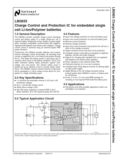
LM3655Charge Control and Protection IC for embedded single cell Li-Ion/Polymer batteries1.0General DescriptionThe LM3655provides complete charge control,discharge control and battery safety of a single Lithium-Ion cell.It supports battery charging by using a variety of power supply types including unregulated current-limited wall adapters,regulated wall adapters and vehicle power adapters.Charge current control is achieved using an external bipolar PNP power transistor.Furthermore,the LM3655provides effective and compre-hensive discharge control functionality.All operating load current is supplied by the Li-Ion battery and passes through this IC.This allows the battery power to disconnect due to overload,short-circuit or low battery conditions.The IC also offers extensive battery safety protection against over-voltage and over-current.The internal safety circuit is backed up by an identical circuit to provide safety redun-dancy.The LM3655requires minimal external components and is packaged in a micro surface mount device for inte-gration in a single cell battery pack.2.0Key Specificationsn 1%precision pin-selectable nominal 4.10V and 4.16V termination voltagesn Up to 1.2A full-rate charge current n Safety Shunt voltage 4.35Vn 800mW power regulation of external PNP at 25˚Callows operation up to 30V (peak-to-peak)and 18V DC3.0Featuresn Input over-voltage protection for load and battery pack n Input over-current protection for load and battery pack n Reverse current protection n Reverse charger protectionn Input short circuit protection that protects the cell from a short on the charger-connectorn Output overload current and short circuit protection n Complete charge control with pre-charging for depleted batteries,full-rate and trickle charging.n Support for charging with regulated and non-regulated wall adapters and vehicle power adapters.n Power regulation of the external Power PNP n Chemistry selection for Li-ion and Li-polymern Complete linear Peak detector function for filtering ripple on input power supplynDigital filtering of the cell voltage transients duringtransmit pulses when LM3655is used in a battery pack for cell phones.n25-pin,2.5mm x 2.5mm microSMD package formounting on four layered PCB inside the battery pack.4.0Applicationsn Cell phones and other portable applications which use embedded Li-ion batteries5.0Typical Application Circuit20111501Because the LM3655and associated external components provide safety protection for both the Li-Ion cell and the phone circuitry,appropriate precautions must be taken in system design and layout to ensure proper operation.November 2004LM3655Charge Control and Protection IC for embedded single cell Li-Ion/Polymer batteries©2004National Semiconductor Corporation Table of Contents1.0General Description .....................................................................................................................................12.0Key Specifications ........................................................................................................................................13.0Features .......................................................................................................................................................14.0Applications ..................................................................................................................................................15.0Typical Application Circuit ............................................................................................................................16.0Connection Diagrams and Package Marking ..............................................................................................37.0LM3655Pin Description ...............................................................................................................................38.0Ordering Information ....................................................................................................................................49.0Operation Description ..................................................................................................................................410.0Pin Functions .............................................................................................................................................410.1V IN ............................................................................................................................................................410.2CELL ........................................................................................................................................................410.3RADIO_B+...............................................................................................................................................410.4V DETECT ...................................................................................................................................................510.5DISABLE .................................................................................................................................................510.6CHEMISTRY ............................................................................................................................................510.7HIB_EN ....................................................................................................................................................510.8HIS_DIS ...................................................................................................................................................510.9BATT_DETB ............................................................................................................................................510.10CHRG_STATE .......................................................................................................................................510.11CHRG_DET ...........................................................................................................................................510.12CNTRL ...................................................................................................................................................510.13EXT_PWR_ON ......................................................................................................................................611.0Charge Control Functions ..........................................................................................................................611.1GENERAL OPERATION ..........................................................................................................................611.2EXTERNAL POWER SUPPLY DETECT .................................................................................................611.2.1V DETECT Circuit ...................................................................................................................................611.2.2Debounce Function ............................................................................................................................711.2.3Power Supply Test Pulses .................................................................................................................811.2.4Low Cell Voltage Charging (Pre-Charging).......................................................................................911.2.5Full-Rate Charging ...........................................................................................................................1011.2.6Trickle/Top-Off Mode ........................................................................................................................1111.2.7Peak Detector Function ....................................................................................................................1112.0Discharge Control Functions ....................................................................................................................1212.1GENERAL DESCRIPTION ....................................................................................................................1212.2RADIO+GENERATION ........................................................................................................................1212.3UNDER-VOLTAGE CUT-OFF ...............................................................................................................1312.4POWER CUT OPERATION ..................................................................................................................1312.5HIBERNATION MODE ..........................................................................................................................1313.0Safety Functions ......................................................................................................................................1313.1INPUT OVER-VOLTAGE PROTECTION ..............................................................................................1313.1.1Normal Operation (Q1Control).......................................................................................................1313.1.2Safety Shunt/Crowbar Operation .....................................................................................................1413.1.3Standby Shunt Mode .......................................................................................................................1413.1.4Thermal Crowbar Mode ...................................................................................................................1413.1.5Fast Shunt Operation ......................................................................................................................1413.1.6Shunt Circuit Parametric Specifications ..........................................................................................1413.2SCHOTTKY ELIMINATION MODE (CHARGER INPUT SHORT CIRCUIT/REVERSE CURRENT PRO-TECTION)......................................................................................................................................................1513.3REVERSE CHARGER PROTECTION ..................................................................................................1513.4OUTPUT CURRENT OVERLOAD PROTECTION (“PTC”MODE)......................................................1513.5OUTPUT SHORT CIRCUIT CURRENT PROTECTION .......................................................................1514.0Required External Components ...............................................................................................................1714.1CHARGE PASS TRANSISTOR (Q1)....................................................................................................1714.2DRIVER TRANSISTOR AND BIAS RESISTORS (R2,R3AND R5)....................................................1714.3EXTERNAL CHARGER SENSE RESISTOR (R4)................................................................................1714.4CAPACITORS ........................................................................................................................................1714.5FUSE (F1).............................................................................................................................................1715.0Electrical Characteristics ..........................................................................................................................1715.1GENERAL SPECIFICATION AND ABSOLUTE MAXIMUM RATINGS ................................................1715.2PASS DEVICE AND POWER SUPPLY RATINGS ...............................................................................1815.3IC PIN ELECTRICAL CHARACTERISTICS .. (18)L M 36552Table of Contents(Continued)16.0Physical Dimensions (21)6.0Connection Diagrams and Package Marking20111502MicroSMD Top ViewSee NS Package Number TLA2520111503MicroSMD Bottom View7.0LM3655Pin DescriptionPin #Name I/O Type DescriptionA1CHEMISTRYInputLogicA low input sets the constant voltage and termination voltage to the lower V TERML .A high input sets the constant voltage to the higher voltage level V TERMH .This pin has an internal 100k Ωpull-downresistor and can be controlled by a peripheral IC or can be tied directly to B+or GND.A2HIB_DISB Input LogicThis pin is internally pulled up to the CELL pin by a 100K resistor.When this pin is momentarily pulsed low,Hibernate mode is exited,which turns on M4.A3HIB_EN Input AnalogThe IC is configured in hibernation mode,when this pin is pulled high after a debounce period.Activating hibernation mode turns off the internal M4transistor.A4EXT_PWR_ON Output LogicEXT_PWR_ON is a push-pull output.It is a logic 1(Radio_B+voltage level)when the cell has reached the V phone_on level (nominally 3.0V)while the charger is connected and the battery is present.A5CNTRL Output Analog This output pin regulates the charger current by controlling the base voltage of the external drive and pass transistors Q2and Q1.B1,C1,C2,D1RADIO OutputAnalogThis is the power supply terminal for the phone.ALL load current from the cell must be sourced from this pin.B2NCThis pin must be left floating.It needs to be connected to a nonconnected PCB pad for heat sinking.It cannot be connected to other NC pins.B3,C3,D3CELL I/O Analog These pins need to be connected to the cell’s positive terminal.B4,C4,D4V IN Input AnalogInput from the pass transistor Q1.B5,C5,D5GND GroundGround pin for the circuit and CELL-D2NCThis pin must be left floating.It needs to be connected to a nonconnected PCB pad for heat sinking.It cannot be connected to other NC pins.E1DISABLEInputLogicA logic high applied to this input disables the charging.A logic low enables it.This pin has an internal 100K Ωpull-down resistor and can be left unconnected.LM365537.0LM3655Pin Description(Continued)Pin #Name I/O Type DescriptionE2BATT_DETBInputLogicThis pin is used to detect the presence of a battery.When the battery is missing,the internal 100K resistor will pull up this pin to the voltage on CELL.When the battery is present,this pin should be pulled low.E3CHRG_STATE OutputOpen DrainThis pin is used to indicate the charge status.An external 30K pull-up resistor needs to be connected between this pin and RADIO+if output on this pin is desired.A low output signifies that the IC is charging the battery cell in full-rate mode.A high output indicates that trickle/top-off charging is in process.The output is also high when the charger is disabled (DIS pin tied high).E4CHRG_DETB OutputOpen DrainAn external 30K pull-up resistor needs to be connected between this pin and RADIO+if output on this pin is desired.The CHRG_DETB indicates whether an external power supply has been detected (output =low)or not (output =high).E5VDET Input AnalogVDET provides the internal control with a signal that is proportional to the external voltage level and also provides power to the internal control circuitry.8.0Ordering InformationOrder Number Packaging Type NSC Package Marking (*)Supplied AsLM3655TL 25-bump Wafer LevelChip Scale (micro SMD)XY TT S50250units,Tape-and-Reel LM3655TLXXY TT S503000units,Tape-and-Reel(*)XY -denotes the date code marking (2digits)in production (*)TT -refers to die/lot tracking for production (*)S -product line designatorPackage markings may change over the course of production9.0Operation DescriptionRefer to Typical Application Circuit for external and internal component reference designators such as Q1,M5,etc.10.0Pin Functions10.1V INV IN is the input pin for the charging current from the external power source to the battery/cell.When the phone is operating from an external supply,cell phone operating current also passes through this pin.Total input current into the V IN pin is internally sensed by monitoring the voltage drop across the series sensing FET M5.V IN is derived from the output (collector)of Q1,and not directly connected to the external source.If the external power supply (VPS)potential exceeds a maximum safe limit,Q1will be controlled to protect the cell and phone circuits from over-voltage.Q1provides the primary over-voltage protection mechanism for the phone circuits and the cell.10.2CELLCELL is connected directly to the battery/cell positive terminal.Under normal operation of the phone,it serves as the main power supply pin for the LM3655.When the phone is drawing current from the battery,current will flow into this pin and out through the internal FET M4to supply the phone’s operating rail (RADIO_B+).When connected to an external supply to charge the battery,current will flow through M5and out of this pin into the cell.If the phone is being operated while connected to an external power supply,the phone’s operating current (current out of the RADIO_B+pin)will be the sum of the currents into the CELL and V IN pins.10.3RADIO_B+All power for the phone’s operation (other than battery charging)is derived from this pin.The phone’s operating current flows through M4,which is controlled and monitored to prevent overload or short-circuit currents,and disabled during cell under-voltage conditions.L M 3655 4LM3655 10.0Pin Functions(Continued)10.4V DETECTThis pin is coupled to the external power supply through a series resistance(R4).It is used to determine when an external source (charger)is connected,which in turn initiates the device’s charge control logic.The CHRG_DETB output is set based on input tothis pin.10.5DISABLEThe phone can stop the charge current through use of the DISABLE logic input pin of the IC.Asserting a logic high on the DISABLE Pin of the IC will force the control pin(CNTRL)to turn off the external Drive(Q2)and Pass(Q1)transistors so thereis no charge current to the cell.The DISABLE input can be driven high by the phone’s logic at any time to interrupt the charge e of the DISABLE pin during charging can allow the phone to measure the cell’s true voltage by peripheral circuitry (without the presence of charge current input)if desired.Additionally,a high-to-low transition on the DISABLE pin(thus re-enabling the charger operation),will reset the charge controlstate machine.10.6CHEMISTRYThe CHEMISTRY pin provides a logic input to the IC that determines the termination threshold for Li-ion cell charging.A logic low applied to this pin selects the lower charging threshold or termination voltage(V TERML),a logic high selects the higher charging threshold(V TERMH).Because different cell types may require slightly different charge termination thresholds,the LM3655supports a pin-programmable selection between two different settings.The lower threshold is nominally4.10V,and the higher threshold is nominally4.16V.10.7HIB_ENThis pin provides a logic input to the IC that when held high during a debounce period of32mS,M4will be latched open evenif the cell voltage is above V CHARGE_LOW.This pin has a10K pull-down resistor internal to the IC so that the IC will default on.10.8HIS_DISThis pin provides a logic input to the IC that when held low momentarily,the latch holding M4open is cleared allowing it to beclosed when the cell voltage is above V CHARGE_LOW.This pin has a100K pullup resistor to the CELL pin internal to the IC.10.9BATT_DETBBATT_DETB indicates to the LM3655IC that a cell is present in the system.This pin provides a logic input to the IC that whenheld low,the IC will be able to detect the presence of a charger.There is a100K pull-up resistor internal to the IC on this pin,whichis supplied from the charger(not from the cell).A series10K resistor is to be used between this pin and the removable battery to protect the IC against ESD.10.10CHRG_STATECHRG_STATE is an open-drain logic output to the phone,and can be used to provide a simple battery-metering indication duringcharge mode.During charge mode,with current flowing into the cell,the Li-ion cell voltage cannot be used for an accurate indication of state of charge.If a battery is at a relatively low state of charge,it will remain in the“full-rate”charge mode for someperiod of time when connected to the external power supply.When the cell reaches a higher state of charge,the charge control switches to the trickle/top-off mode.Thus,this signal is logic low during full-rate charge mode and high during the trickle/top-off mode.The exact percentage of“full”at this crossover point will vary depending on many conditions,primarily full-rate charge current level,but is expected to be>60%for typical use with a mid-rate charger.This information can be used to provide a simple“charging”or“ready”indication by the system for the battery status meter during charge.If combined with a timer,or other means of interaction by the system(such as periodic control of the DISABLE pin combined with cell voltage measurements during periods of no current flow)a more complete metering method may be implemented if desired.10.11CHRG_DETThis is an open-drain output to the phone’s power management IC that indicates the connection of an external power supply. Typical application uses a30K pull-up resistor to RADIO_B+.When a charger is detected,this output is pulled LOW by the internal logic of the LM3655.This signal may be pulled up to a low-voltage logic rail such as2.75V or1.8V regulated voltage.Itis assumed that the voltage used to pull-up is no higher than the cell voltage.10.12CNTRLThis is an analog output to control Q2,the NPN drive transistor.The CNTRL output is adjusted to deliver the appropriate level ofcurrent required by the charge algorithm for full-rate or trickle/top-off charging.During full-rate charging,CNTRL is set such thatQ1will be saturated.During trickle/top-off mode,CNTRL will be set in order to maintain the appropriate cell clamp voltage(4.10Vor4.16V as desired).Furthermore,if the power-monitoring circuit determines that excess power is being dissipated in,the CNTRLsignal will be further reduced to limit current flowing through Q1.This ensures that the Q1pass device remains within safe power dissipation limits.510.0Pin Functions(Continued)10.13EXT_PWR_ONEXT_PWR_ON is a digital push-pull output.A logic 1,referenced to the Radio_B+level is output when V cell exceeds V phone_on (nominally 3.00V)and CHRG_DETB =0(charger presence is detected)and BATT_DETB is low.Otherwise,EXT_PWR_ON is held low to prevent the phone from attempting to turn on due to charger connection when there is either no battery present or when the battery is not charged enough for the phone to operate.11.0Charge Control Functions11.1GENERAL OPERATIONThe LM3655circuit is able to operate with different types of charge power supplies with a wide range of input voltage and currents,including but not limited to unregulated current limited wall adapters,regulated wall adapters and Vehicle Power Adapters with 1A of current limit.The IC protects itself from high voltages by using Q1and Q2to stand off these voltages.It also uses resistors to current limit the V DETECT pin.High currents are handled by using current regulation during both the full-rate and the trickle/top-off phases of charging the battery.Power dissipation in Q1is controlled using a constant-power control circuit within the IC.The LM3655has multiple modes of operation for charging and protecting the embedded cell.The three basic modes of operation are low voltage charging,full-rate charging,and trickle charging.During the charge process,the power dissipation in the pass element Q1is monitored and controlled to a safe maximum limit by reducing charge current as necessary.Because of quantization error or power supply voltage fluctuations,the power-limiting circuit may (in some cases)reduce cell current to a level lower than necessary for extended periods of time.To counteract this,the IC periodically activates a charger test pulse during the full-rate and trickle charging modes.This allows the power supply to deliver full-rate current,although the cell voltage is always regulated such that it does not exceed the termination voltage (4.10V or 4.16V as determined by the CHEMISTRY pin).The test pulse allows the cell to be charged at the fastest possible rate by allowing the charge control to re-enter the full-rate charge (Q1saturated)mode whenever possible.The test pulses are enabled during full-rate and trickle/top-off charge modes,have a nominal duration of 256mS,and are repeated every 64seconds.This is referred to as ‘burp’mode.Figure 1shows the cell voltage thresholds used in the selection of the charging modes.The horizontal (time)axis is intended to illustrate the progression of a complete charge/discharge cycle of operation.11.2EXTERNAL POWER SUPPLY DETECT11.2.1V DETECT CircuitThe V DETECT circuit is used to determine the presence of an external charger.The equivalent circuit is illustrated below.20111504FIGURE 1.Voltage ThresholdsL M 3655 611.0Charge Control Functions(Continued)The Shunt Regulator (Z1)on the V DETECT pin is designed to sink a limited amount of current while maintaining certain levels of regulation.These are specified below.When there is excessive current flowing into the V DETECT pin above which Z1can regulate,then current can flow through D1into the cell pin.When the cell pin voltage exceeds V SHUNT ,I CELL_SHUNT turns on.The I CELL_SHUNT circuit is implemented redundantly.I CELL_SHUNT shunts current to ground through effectively 100Ωwhen both redundant circuits are operating.V DETECT circuit parametric specs are summarized below.These specs apply to the entire Normal Temperature Range.Parameter DescriptionMin TypMaxUnits I DETECTMIN1Min V DETECT pin current to allow detection of a charger 100µA I UNDETECTMAX Maximum current into the V DETECT pin for the charger to be not detected.3µA I DETECTMIN2Once a charger is detected,it will remain detected unless the current into the V DETECT pin goes below this threshold 25µA I CELL_SHUNT V CELL current.With V CELL =4.5V (>V SHUNT )2075mA I DETECTMAX Max V DETECT pin current that can maintain V DETECTMAX115mA V DETECTMAX1Normal V DETECT regulation voltage,I DETECTMIN <I DETECT <I DETECTMAXV CELL –5mV V CELL ±50mV V V DETECTMAX2Secondary V DETECT voltage limit,I DETECTMAX <I DETECT <30mAV CELL 1VV11.2.2Debounce FunctionThe charger debounce detects a temporary disconnect/connect of the charging power supply.This can occur when the end-user inserts the power supply to the phone and the connection is not made cleanly,or if the connection is disturbed (such as dropping the phone).When the IC first senses the power supply input voltage it will delay τDEBOUNCE_ON before the charger detect signal is confirmed.If there is disconnect of the charge power supply,the IC will delay τDEBOUNCE_OFF before the disconnection is confirmed.The IC will ignore the interruptions of duration shorter than specified.These specs apply to the entire Normal Temperature Range.20111505FIGURE 2.V DETECT CircuitLM3655711.0Charge Control Functions(Continued)SpecificationTest ConditionsMin Typ Max Units Debounce Connection Delay “τDEBOUNCE_ON ”I DETECT stepped from 0mA to 1mA 223264ms Debounce Connection Delay “τDEBOUNCE_OFF ”I DETECT stepped from 1mA to 0mA223264ms11.2.3Power Supply Test PulsesThe purpose of the test pulse operation is for the IC to periodically test the charging power supply’s full-rate current capability.This operation only occurs when the cell voltage is above V PHONE_ON .The test pulse has a period of τTEST_PERIOD and pulse width of τTEST_WIDTH .During test pulses the IC will fully turn on the M5pass devices and attempts to draw I CHRG_MAX current from the charging power supply.The charging power supply will respond by delivering the full-rate current up to I CHRG-MAX to the load (Q1will be forced into saturation).During the test pulse,the IC constantly monitors the cell voltage with its internal voltage regulation control circuit and the charge current with its current regulation control circuit.The power dissipation of Q1is not controlled during the test pulse.The IC determines which charge rate to apply at the end of each test pulse.The interaction between the three control circuits is such that the voltage regulation is the most dominant so the cell voltage will not exceed V TERMX .(V TERMX being either V TERMH or V TERML ,depending on the logic level applied to the CHEMISTRY pin).When the test pulse is high,one of the following can occur:1.V PHONE_ON <V CELL <V TERMX and Charge Current <I CHRG_MAX :The charging power supply will continue to deliver full-rate current during and after the test pulse.Q1remains in saturation and all M5sense resistor switches remain on.2.V PHONE_ON <V CELL <V TERMX and Charge Power Supply wants to deliver more than I CHRG_MAX (e.g.Failed Vehicular Power Adaptor and phone is connected directly to car battery):The internal current regulation control of the LM3655IC will try to maintain the charge current at I CHRG_MAX by forcing the external Q1and Q2transistors into linear operation.This may exceed Q1power dissipation limit.After the test pulse,the IC internal power regulation control senses the voltage across Q1V CE above Q1UNSAT and determines the appropriate M5sense resistor array switches to turn on.The effective resistance will determine the amount of charge current allow such that Q1power dissipation is within limit of P PASS_MAX .If Q1UNSAT is exceeded at the end of a test pulse,CHRG_STATE will not go high as the Top-off signal is only created when V CELL reaches V TERMX .Unless a non-supported power supply is used,because of burp mode,it is expected that the system will mend itself and go back into full-rate when the next test pulse comes along.3.V CELL reaches V TERMX (desired maximum cell clamp level):The IC internal voltage regulation control will dominate the charger control logic,and control the charge current to maintain V CELL at V TERMX .To accomplish this,the voltage regulation control forces Q1and Q2from saturation back in linear mode to reduce the charge current to a level that will maintain V CELL at V TERMX .After the test pulse,Q1V CE above Q1UNSAT indicates the charge current to be reduced to trickle current.Q1may or may not be in power-limit regulation.In order to prevent a transient situation when transitioning from trickle to full-rate between test pulses,the voltage regulation control will reset to zero for τTEST_DELAY and the current regulation control will then be forced to turn off Q1and Q2.This in effect will set the charge current to zero.After τTEST_DELAY the voltage regulator will be allowed to ramp back up and the charge current will also ramp from zero to full-rate current.Figure 3illustrates the charge profile.L M 3655 8。
951200301资料

F eatures Array•Integer Unit Based on SPARC V7 High-performance RISC Architecture•Optimized Integrated 32/64-bit Floating-point Unit•On-chip Peripherals–EDAC and Parity Generator and Checker–Memory InterfaceChip Select GeneratorWaitstate GenerationMemory Protection–DMA Arbiter–TimersGeneral Purpose Timer (GPT)Real-time Clock Timer (RTCT)Watchdog Timer (WDT)–Interrupt Controller with 5 External Inputs–General Purpose Interface (GPI)–Dual UART•Speed Optimized Code RAM Interface8- or 40-bit boot-PROM (Flash) Interface•IEEE 1149.1 Test Access Port (TAP) for Debugging and Test Purposes•Fully Static Design•Performance: 20 MIPs/5 MFlops (Double Precision) at SYSCLK = 25 MHz•Core Consumption: 1.0W Typ. at 20 MIPs/0.7W typ. at 10 MIPs•Operating Range: 4.5V to 5.5V(1) -55°C to +125°C•Tested up to Total Dose of 300 KRADs (Si) according to MIL STD 883 Method 1019•SEU Event Rate Better than 3 E-8 Error/Component/Day (Worst Case)•No Single Event Latch-up below an LET Threshold of 80 MeV/mg/cm2•Quality Grades: ESCC with 9512/003 and QML-Q or V with 5962-00540•Package: 256 MQFPF; Bare DieNote: 1.For 3.3V capability see the TSC695FL datasheet on the Atmel site. DescriptionThe TSC695F (ERC32 Single-Chip) is a highly integrated, high-performance 32-bit RISC embedded processor implementing the SPARC architecture V7 specification. It has been developed with the support of the ESA (European Space Agency), and offers a full development environment for embedded space applications.The processor is manufactured using the Atmel 0.5 µm radiation tolerant (≥ 300 KRADs(Si)) CMOS enhanced process (RTP). It has been specially designed for space, as it has on-chip concurrent transient and permanent error detection.The TSC695F includes an on-chip Integer Unit (IU), a Floating Point Unit (FPU), a Memory Controller and a DMA arbiter. For real-time applications, the TSC695F offers a high security watchdog, two timers, an interrupt controller, parallel and serial inter-faces. Fault tolerance is supported using parity on internal/external buses and an EDAC on the external data bus. The design is highly testable with the support of anOn-Chip Debugger (OCD), and a boundary scan through JTAG interface.2TSC695F4118J–AERO–08/04Block DiagramFigure 1. TSC695F Block DiagramPin DescriptionsFor pin assignment, refer to package section.General PurposeInterfaceUART ATAPClock ManagtError ManagtGeneral PurposeTimer Real Time ClockTimer32-bit Integer UnitDMA Arbiter Access Controller Address Interface Wait State ControllerInterruptsRxD, TxD GPI bits DMA CtrlMem Ctrl Ready/Busy Add.+Size+ASI Data+Check bits ParitiesEDACWatch DogParity Parity Gen./Check.Reset&UART B Interrupt Controller32/64-bitFloating-PointUnit ParityGen./Chk.Gen./Chk.Table 1. Pin DescriptionsSignal Type Active DescriptionRA[31:0]I/O, 32-bit registered address busOutput buffer: 400 pFRAPAR I/O High Registered address bus parity-RASI[3:0]I/O 4-bit registered address space identifier -RSIZE[1:0]I/O 2-bit registered bus transaction size-RASPAR I/O High Registered ASI and SIZE parity -CPAR I/O HighControl bus parity -D[31:0]I/O 32-bit data bus -CB[6:0]I/O 7-bit check-bit bus-DPAR I/O High Data bus parity-RLDSTO I/O High Registered atomic load-store -ALE O Low Address latch enable -DXFER I/O High Data transfer -LOCK I/O High Bus lock -RD I/O High Read access -WE I/O Low Write enable -WRT I/O High Advanced write -MHOLD O Low Memory bus hold MHOLD+FHOLD +BHOLD+FCCVMDS O Low Memory data strobe -MEXC O Low Memory exception -PROM8I Low Select 8-bit wide PROM-BA[1:0]O Latched address used for 8-bit wide boot PROM -ROMCS O Low PROM chip select -ROMWRT I Low ROM write enable -MEMCS[9:0]O Low Memory chip select Output buffer: 400 pF MEMWROLowMemory write strobeOutput buffer: 400 pF3TSC695F4118J–AERO–08/04Note:If not specified, the output buffer type is 150 pF, the input buffer type is TTL.OE O Low Memory output enable Output buffer: 400 pFBUFFEN O Low Data buffer enable -DDIR O High Data buffer direction -DDIR O Low Data buffer direction -IOSEL[3:0]O Low I/O chip select-IOWR O Low I/O and exchange memory write strobe -EXMCS O Low Exchange memory chip select -BUSRDY I Low Bus ready-BUSERR I Low Bus error -DMAREQ I Low DMA request -DMAGNT O Low DMA grant-DMAAS I High DMA address strobe-DRDY O Low Data ready during DMA access -IUERR O Low IU error-CPUHALT O Low Processor (IU & FPU) halt and freeze -SYSERR O Low System error -SYSHALT I Low System halt -SYSAV O High System availability -NOPAR I Low No parity-INULL O High Integer unit nullify cycle -INST O High Instruction fetch Used to check the executestage of IUinstruction pipelineFLUSH O High FPU instruction flush DIA O High Delay instruction annulled RTC O HighReal Time Clock Counter output -RxA/RxB I Receive data UART ’A’ and ’B’Input triggerTxA/TxB O Transmit data UART ’A’ and ’B’-GPI[7:0]I/O GPI input/output Input triggerGPIINT O High GPI interrupt -EXTINT[4:0]I External interruptInput triggerEXTINTACK O High External interrupt acknowledge -IWDE I High Internal watch dog enable -EWDINT I High External watch dog input interrupt Input triggerWDCLK I Watch dog clock -CLK2I Double frequency clock -SYSCLK O System clock-RESET O Low Output reset-SYSRESET I Low System input reset Input trigger TMODE[1:0]I Factory test mode Functional mode=00DEBUG I High Software debug mode -TCK I T est (JTAG) clock -TRST I Low T est (JTAG) reset pull-up ≈ 37 k ΩTMS I T est (JTAG) mode select pull-up ≈ 37 k ΩTDI I T est (JTAG) data input pull-up ≈ 37 k ΩTDO OT est (JTAG) data output -VCCI/VSSI Main internal power -VCCO/VSSOOutput driver power-Table 1. Pin Descriptions (Continued)Signal Type Active Description4TSC695F4118J–AERO–08/04System ArchitectureThe TSC695F is to be used as an embedded processor requiring only memory and application specific peripherals to be added to form a complete on-board computer. All other system support functions are provided by the core.Figure 2. System Architecture Based on TSC695FTSC695F5TSC695F4118J–AERO–08/04P roduct D escriptionInteger UnitThe Integer Unit (IU) is designed for highly dependable space and military applications,and includes support for error detection. The RISC architecture makes the creation of a processor that can execute instructions at a rate approaching one instruction per pro-cessor clock possible.To achieve that rate of execution, the IU employs a four-stage instruction pipeline that permits parallel execution of multiple instructions. •Fetch - The processor outputs the instruction address to fetch the instruction.•Decode - The instruction is placed in the instruction register and is decoded. The processor reads the operands from the register file and computes the next instruction address.•Execute - The processor executes the instruction and saves the results in temporary registers. Pending traps are prioritized and internal traps are taken during this stage.•Write - If no trap is taken, the processor writes the result to the destination register.All four stages operate in parallel, working on up to four different instructions at a time. A basic ‘single-cycle’ instruction enters the pipeline and completes infour cycles.By the time it reaches the write stage, three more instructions have entered and are moving through the pipeline behind it. So, after the first four cycles, a single-cycle instruction exits the pipeline and a single-cycle instruction enters the pipeline on every cycle. Of course, a ’single-cycle’ instruction actually takes four cycles to complete, but they are called single cycle because with this type of instruction the processor can com-plete one instruction per cycle after the initial four-cycle delay.Floating-point UnitThe FLoating Point Unit (FPU) is designed to provide execution of single and double-precision floating-point instructions concurrently with execution of integer instructions by the IU. The FPU is compliant to the ANSI/IEEE-754 (1985) floating-point standard.The FPU is designed for highly dependable space and military applications, and includes support for concurrent error detection and testability.The FPU uses a four stage instruction pipeline consisting of fetch, decode, execute and write stages (F, D, E and W). The fetch unit captures instructions and their addresses from the data and address buses. The decode unit contains logic to decode the floating-point instruction opcodes. The execution unit handles all instruction execution. The exe-cution unit includes a floating-point queue (FP queue), which contains stored floating-point operate (FPop) instructions under execution and their addresses. The execution unit controls the load unit, the store unit, and the datapath unit. The FPU depends upon the IU to access all addresses and control signals for memory access. Floating-point loads and stores are executed in conjunction with the IU, which provides addresses and control signals while the FPU supplies or stores the data. Instruction fetch for integer and floating-point instructions is provided by the IU.The FPU provides three types of registers: f registers, FSR, and the FP queue. The FSR is a 32-bit status and control register. It keeps track of rounding modes, floating-point trap types, queue status, condition codes, and various IEEE exception information. The floating-point queue contains the floating-point instruction currently under execution,along with its corresponding address.6TSC695F4118J–AERO–08/04Instruction SetTSC695F instructions fall into six functional categories: load/store, arithmetic/logi-cal/shift, control transfer, read/write control register, floating-point, and miscellaneous.Please refer to SPARC V7 Instruction-set Manual.Note:The execution of IFLUSH will cause an illegal instruction trap.On-chip PeripheralsMemory Interface The TSC695F is designed to allow easy interfacing to internal/external memory resources.System RegistersThe system registers are only writable by IU in the supervisor mode or by DMA during halt mode.Table 2. Memory MappingMemory ContentsStart Address Size (bytes)Data Size and Parity Options Boot PROM0x 0000 0000128K → 16M8-bit mode No parity/-No EDAC/-Only byte write 40-bit modeParity + EDAC mandatory/-Only word write Extended PROM0x 0100 0000Max: 15M8-bit mode No parity/-No EDAC/-Only byte write 40-bit modeParity + EDAC mandatory/-Only word writeExchange Memory 0x 01F0 00004k → 512k Parity + EDAC option/-Only word write System Registers 0x 01F8 0000512K (124 used)Parity/-Only word read/write access RAM (8 blocks)0x 0200 00008*32K → 8*4M Parity + EDAC option/-All data sizes allowedExtended RAM 0x 0400 0000Max: 192M I/O Area 00x 1000 00000 → 16M Parity option/-All data sizes allowedI/O Area 10x 1100 00000 → 16M I/O Area 20x 1200 00000 → 16M I/O Area 30x 1300 00000 → 16M Extended I/O Area 0x 1400 0000Max: 1728M Extended General0x 8000 0000Max: 2GNo parity/-All data sizes allowed Table 3. System Registers Address MapSystem Register Name Address System Control Register SYSCTR 0x 01F8 0000Software Reset SWRST 0x 01F8 0004Power DownPDOWN 0x 01F8 0008System Fault Status Register SYSFSR 0x 01F8 00A0Failing Address Register FAILAR 0x 01F8 00A4Error & Reset Status Register ERRRSR 0x 01F8 00B0Test Control RegisterTESCTR0x 01F8 00D07TSC695F4118J–AERO–08/04Wait-state and Time-out GeneratorIt is possible to control the wait-state generation by programming a Wait-state Configu-ration Register. The maximum programmable number of wait-states is applied by default at reset.It is possible to program the number of wait-states for the following combinations:–RAM read and write–PROM read and write (i.e. EEPROM or Flash write)–Exchange Memory read/write–Four individual I/O peripherals read/writeA bus time-out function of 256 system clock cycles is provided for the bus ready con-trolled memory areas, i.e., the Extended PROM, Exchange Memory, Extended RAM,Memory Configuration Register MCNFR 0x 01F8 0010I/O Configuration Register IOCNFR 0x 01F8 0014Waitstate Configuration RegisterWSCNFR 0x 01F8 0018Access Protection Segment 1 Base Register APS1BR 0x 01F8 0020Access Protection Segment 1 End Register APS1ER 0x 01F8 0024Access Protection Segment 2 Base Register APS2BR 0x 01F8 0028Access Protection Segment 2 End Register APS2ER 0x 01F8 002C Interrupt Shape Register INTSHR 0x 01F8 0044Interrupt Pending Register INTPDR 0x 01F8 0048Interrupt Mask Register INTMKR 0x 01F8 004C Interrupt Clear Register INTCLR 0x 01F8 0050Interrupt Force Register INTFCR 0x 01F8 0054Watchdog Timer Register WDOGTR 0x 01F8 0060Watchdog Timer Trap Door SetWDOGST 0x 01F8 0064Real Time Clock Timer <Counter> Register RTCCR 0x 01F8 0080Real Time Clock Timer <Scaler> Register RTCSR 0x 01F8 0084General Purpose Timer <Counter> Register GPTCR 0x 01F8 0088General Purpose Timer <Scaler> Register GPTSR 0x 01F8 008C Timers Control RegisterTIMCTR 0x 01F8 0098General Purpose Interface Configuration Register GPICNFR 0x 01F8 00A8General Purpose Interface Data Register GPIDATR 0x 01F8 00AC UART ’A’ Rx & Tx Register UARTAR 0x 01F8 00E0UART ’B’ Rx & Tx Register UARTBR 0x 01F8 00E4UART Status RegisterUARTSR0x 01F8 00E8Table 3. System Registers Address Map (Continued)System Register Name Address8TSC695F4118J–AERO–08/04Extended I/O and the Extended General areas.EDACThe TSC695F includes a 32-bit EDAC (Error Detection And Correction). Seven bits (CB[6:0]) are used as check bits over the data bus. The Data Bus Parity signal (DPAR)is used to check and generate the odd parity over the 32-bit data bus. This means that altogether 40 bits are used when the EDAC is enabled.The TSC695F EDAC uses a 7-bit Hamming code which detects any double bit error on the 40-bit bus as a non-correctable error. In addition, the EDAC detects all bits stuck-at-one and stuck-at-zero failure for any nibble in the data word as a non-correctable error.Stuck-at-one and stuck-at-zero for all 32 bits of the data word is also detected as a non-correctable error.Memory and I/O ParityThe TSC695F handles parity towards memory and I/O in a special way. The processor can be programmed to use no parity, only parity or parity and EDAC protection towards memory and to use parity or no towards I/O. The signal used for the parity bit is DPAR.Memory RedundancyProgramming the Memory Configuration Register, the TSC695F provides chip selects for two redundant memory banks for replacement of faulty banks.Memory Access Protection•Unimplemented Areas - Access to all unimplemented memory areas are handled by the TSC695F and detected as illegal.•RAM Write Access Protection - The TSC695F can be programmed to detect and mask write accesses in any part of the RAM. The protection scheme is enabled only for data area, not for the instruction area. The programmable write access protection is based on two segments.•Boot PROM Write Protection - The TSC695F supports a qualified PROM write for an 8-bit wide PROM and/or for a 40-bit wide PROM.DMADMA InterfaceThe TSC695F supports Direct Memory Access (DMA). The DMA unit requests access to the processor bus by asserting the DMA request signal (DMAREQ). When the DMA unit receives the DMAGNT signal in response, the processor bus is granted. In case the processor is in the power-down mode the processor is permanent tri-stated, and a DMAREQ will directly give a DMAGNT. The TSC695F includes a DMA session time-out function.Bus ArbiterThe TSC695F always has the lowest priority on the system bus.TrapsA trap is a vectored transfer of control to the supervisor through a special trap table that contains the first four instructions of each trap handler. The base address of the table is established by supervisor and the displacement, within the table, is determined by the trap type. Two categories of traps can appear.9TSC695F4118J–AERO–08/04Synchronous TrapsTable 4. Synchronous TrapsTrapPriorityTrap Type (tt)CommentsReset1–Sources: SYSRESET* pin software reset watchdog resetIU or System error resetH a r d w a r e E r r o rNon-restartable, imprecise error22.164h Severe error requiring a re-bootTSC695F enters (if not masked) in halt or reset mode Non-restartable,precise error 2.262h Error not removable, PC & nPC OKTSC695F enters (if not masked) in halt or reset mode Register file error 2.365h Special case of non-restartable, precise error.TSC695F enters (if not masked) in halt or reset mode Restartable, late error 2.463h Retrying instruction but PC & nPC have to be re-adjusted TSC695F enters (if not masked) in halt or reset mode Restartable,precise error2.561hRetrying instructionTSC695F enters (if not masked) in halt or reset mode Instruction access(Error on instruction fetch )301h Parity error on control bus Parity error on data bus Parity error on address busAccess to protected or unimplemented area Uncorrectable error in memory Bus time out Bus errorIllegal Instruction 402h –Privileged instruction 503h –FPU disabled604h –WindowOverflow705h During SAVE instruction or trap takenUnderflow06h During RESTORE instruction or RETT instructionMemory address not aligned807h–F P U e x c e p t i o nNon-restartable error 99.108hSevere error, cannot restart the instruction Data bus error 9.2Parity error on FPU data busRestartable error 9.3Can be removed restarting the instructionSequence error 9.4–Unimplemented FPop 9.5–IEEE exceptions:9.6Invalid operation Division by zero Overflow Underflow Inexact10TSC695F4118J–AERO–08/04It is possible to mask each individual interrupt (except Watchdog time-out). The interrupts in the Interrupt Pending Register are cleared automatically when the interrupt is acknowledged.By programming the Interrupt Shape Register, it is possible to define the external interrupts to either be active low or active high and to define the external interrupts to either be edge or level sensitive.Data access exception (Error on data load )1009h Idem “instruction access”System register access violation Tag overflow 110Ah TADDccTV and TSUBccTV instructions Trap instructions1280h to FFhTrap on integer condition codes (Ticc)Table 4. Synchronous Traps (Continued)TrapPriorityTrap Type (tt)CommentsTable 5. Interrupts or Asynchronous TrapsTrap Priority Trap Type (tt)CommentsWatchdog time-out 131Fh Internal or external (EWDINT pin)External INT 4141Eh EXTINTAK on only one of EXTINT[4:0]Real time clock timer 151Dh –General purpose timer 161Ch –External INT 3171Bh EXTINTAK on only one of EXTINT[4:0]External INT 2181Ah EXTINTAK on only one of EXTINT[4:0]DMA time-out 1919h –DMA access error 2018h –UART Error2117h –Correctable error in memory 2216h Data read OK but source not updatedUART B Data readyTransmitter ready 2315h –UART AData readyTransmitter ready2414h –External INT 12513h EXTINTAK on only one of EXTINT[4:0]External INT 02612hEXTINTAK on only one of EXTINT[4:0]Masked hardware errors 2711hLogical OR of:IU hardware error masked IU error mode maskedSystem hardware error maskedTSC695F Timers In software debug mode the timers are controlled by a system register bit and the exter-nal pin DEBUG.General Purpose Timer The General Purpose Timer (GPT) provides, in addition to a generalized counter func-tion, a mechanism for setting the step size in which actual time counts are performed.GPT is clocked by the internal system clock. They are possible to program to be eitherof single-shot type or periodical type and in both cases generate an interrupt when thedelay time has elapsed. The current value of the scaler and counter of the GPT can beread.Real Time Clock Timer The only functional differences between the two timers are that the Real Time ClockTimer (RTCT) has an 8-bit scaler (16-bit scaler for GPT) and that the RTCT interrupt hashigher priority than the GPT interrupt.RTCT information is available on RTC output pin.Watchdog Timer Setting the external pin IWDE to V CC enables the internal watchdog timer. Otherwise thewatchdog function must be externally provided.The watchdog is supplied from a separate external input (WDCLK). After reset, the timeris enabled and starts running with the maximum range. If the timer is not refreshed(reprogrammed) before the counter reaches zero value, an interrupt is sent. Simulta-neously, the timer starts counting a reset time-out period. If the timer is notacknowledged before the reset time-out period elapses, a reset is applied to TSC695F. UARTs Two full duplex asynchronous receiver transmitters (UART) are included. In softwaredebug mode the UART’s are controlled by system register bits.The data format of the UART’s is eight bits. It is possible to choose between even or oddparity, or no parity, and between one and two stop bits. The UART’s provide double buff-ering, i.e. each UART consists of a transmitter holding register, a receiver holdingregister, a transmitter shift register, and a receiver shift register. Each of these registersare 8-bit wide. For each UART a RX and TX Register is provided. The UART’s generatean interrupt each time a byte has been received or a byte has been sent. There isanother interrupt to indicate errors.The baud rate of both the UART’s is programmable. The clock is derived either from thesystem clock or can use the watchdog clock.General Purpose Interface The General Purpose Interface (GPI) is an 8-bit parallel I/O port. Each pin can be config-ured as an input or an output.A falling or rising edge detection is made on each selected GPI inputs. Every input tran-sition on GPI generates an external positive pulse on GPIINT pin of two SYSCLK width. Execution ModesReset Mode Reset mode is entered when:–The SYSRES input is asserted–Software reset which is caused by the software writing to a Software ResetRegister–Watchdog reset which is caused by a Watchdog counter time-out–Error reset which is caused by a hardware parity errorThis RESET output has a minimum of 1024 SYSCLK width to allow the usage of Flashmemories.The error and Reset Status Register contain the source of the last processor reset. Run Mode In this mode the IU/FPU is executing, while all peripherals are running (if softwareenabled).System Halt Mode System Halt mode is entered when the SYSHALT input is asserted. In this mode, the IUand FPU are frozen, while the timers (includeing the internal watchdog timer) andUART’s are stopped.Power Down Mode This mode is entered by writing to the Power-down Register. In this mode, the IU andFPU are frozen. The TSC695F leaves the power-down mode if an external interrupt isasserted.Error Halt Mode Error Halt mode is entered under the following circumstances:– A internal hardware parity error.–The IU enters error mode.The only way to exit Error Halt Mode is through Cold Reset by asserting SYSRESET. Error Handler The TSC695F has one error output signal (SYSERR) which indicates that an unmaskederror has occurred. Any error signalled on the error inputs from the IU and the FPU islatched and reflected in the Error and Reset Status Register. By default, an error leadsto a processor halt.Parity Checking The TSC695F includes:–Parity checking and generation (if required) on the external data bus–Parity checking on the external address bus–Parity checking on ASI and SIZE–Parity checking and generation on all system registers–Parity generation and checking on the internal control bus to the IUAll external parity checking can be disabled using the NOPAR signal.System Clock The TSC695F uses CLK2 clock input directly and creates a system clock signal bydividing CLK2 by two. It drives SYSCLK pin with a nominal 50% duty cycle for the appli-cation. It is highly recommended that only SYSCLK rising edge is used as reference asfar as possible.System Availability The SYSAV bit in the Error and Reset Status Register can be used by software to indi-cate system availability.Test Mode The TSC695F includes a number of software test facilities such as EDAC test, Paritytest, Interrupt test, Error test and a simple Test Access Port. These test functions arecontrolled using the Test Control Register.TSC695FTest and Diagnostic Hardware FunctionsA variety of TSC695F test and diagnostic hardware functions, including boundary scan,internal scan, clock control and On-chip Debugger, are controlled through an IEEE 1149.1 (JTAG) standard Test Access Port (TAP).Test Access PortThe TAP interfaces to the JTAG bus via 5 dedicated pins on the TSC695F chip. These pins are:•TCK (input): T est Clock •TMS (input): Test Mode Select •TDI (input): Test Data Input •TDO (output): Test Data Output •TRST (input): Test ResetInstruction RegisterFive standard instructions are supported by the TSC695F TAP.DebuggingThe design is highly testable with the support of an On-Chip Debugger (OCD), an inter-nal and boundary scan through JTAG interface.Binary Value Name of Instruction Data Register Scan Chain Accessed 00. 0000EXTESTBoundary Scan Register Boundary scan chain 00. 0001SAMPLE/PRELOAD Boundary Scan Register Boundary scan chain 00. 0011INTEST Boundary Scan Register Boundary scan chain 11. 1111BYPASS Bypass Register Bypass register 10. 0000IDCODEDevice ID RegisterID register scan chainElectrical CharacteristicsDC Characteristics Note: Stresses at or above those listed under “Absolute Maximum Ratings” may cause permanent damage to the device. This is a stress rating only and functional operation of the device at these or any other conditions above those indicated in the operational sections of this specification is not implied. Exposure to absolute maximum rating conditions may affect device reliability.Table 6. DC Characteristics at V DD 5V ± 10%Symbol Parameter Min Typ Max Unit Test ConditionsVIL trigger Input Low Voltagefor trigger input––0.8V V CC = 4.5 to 5.5VVIH trigger Input High Voltagefor trigger input3.0––V V CC =4.5 to5.5V∆VT Input Hysteresisfor trigger input–0.9–V V CC = 4.5 to 5.5VVIL TTL Input Low Voltagefor TTL input––0.8V V CC = 4.5 to 5.5VVIH TTL Input High Voltagefor TTL input2.2––V V CC = 4.5 to 5.5VVOL400 pF Output Low Voltagefor 400 pF buffer–0.30.4VV CC = 4.5 to 5.5VIOL = 12 mAVOH400 pF Output High Voltagefor 400 pF buffer2.40.3–VV CC = 4.5 to 5.5VIOH = -16 mAVOL150 pF Output Low Voltagefor 150 pF buffer–0.30.4VV CC = 4.5 to 5.5VIOL = 4 mAVOH150 pF Output High Voltagefor 150 pF buffer2.4 4.3–VV CC = 4.5 to 5.5VIOH = -6 mAIccOP Operating Supply Currentfor core processor––230mAV CC = 5.5V, f = 25 MHz––210V CC = 5.5V, f = 20 MHz––170V CC = 5.5V, f = 10 MHzIccPD Power Down Supply Currentfor core processor––41mAV CC = 5.5V, f = 25MHz––38V CC = 5.5V, f = 20 MHz––30V CC = 5.5V, f = 10 MHz。
STY139N65M5;中文规格书,Datasheet资料
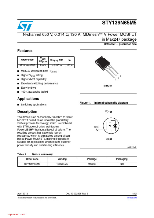
This is information on a product in full production.April 2012Doc ID 022826 Rev 31/12STY139N65M5N-channel 650 V , 0.014 Ω, 130 A, MDmesh™ V Power MOSFETin Max247 packageDatasheet — production dataFeatures■Max247 worldwide best R DS(on)■Higher V DSS rating ■Higher dv/dt capability■Excellent switching performance ■Easy to drive■100% avalanche testedApplications■Switching applicationsDescriptionThe device is an N-channel MDmesh™ V Power MOSFET based on an innovative proprietary vertical process technology, which is combined with STMicroelectronics’ well-knownPowerMESH™ horizontal layout structure. The resulting product has extremely low on-resistance, which is unmatched among silicon-based Power MOSFETs, making it especially suitable for applications which require superior power density and outstanding efficiency.Order code V DSS @T jMAX R DS(on) max I D STY139N65M5710 V< 0.017 Ω130 ATable 1.Device summaryOrder code Marking Package Packaging STY139N65M5139N65M5Max247TubeContents STY139N65M5Contents1Electrical ratings . . . . . . . . . . . . . . . . . . . . . . . . . . . . . . . . . . . . . . . . . . . . 32Electrical characteristics . . . . . . . . . . . . . . . . . . . . . . . . . . . . . . . . . . . . . 42.1Electrical characteristics (curves) . . . . . . . . . . . . . . . . . . . . . . . . . . . . 6 3Test circuits . . . . . . . . . . . . . . . . . . . . . . . . . . . . . . . . . . . . . . . . . . . . . . 8 4Package mechanical data . . . . . . . . . . . . . . . . . . . . . . . . . . . . . . . . . . . . . 9 5Revision history . . . . . . . . . . . . . . . . . . . . . . . . . . . . . . . . . . . . . . . . . . . 122/12Doc ID 022826 Rev 3STY139N65M5Electrical ratingsDoc ID 022826 Rev 33/121 Electrical ratingsTable 2.Absolute maximum ratingsSymbol ParameterValue Unit V GS Gate- source voltage± 25V I D Drain current (continuous) at T C = 25 °C 130A I D Drain current (continuous) at T C = 100 °C 78A I DM (1)1.Pulse width limited by safe operating area.Drain current (pulsed)520A P TOT Total dissipation at T C = 25 °C625W I AR Max current during repetitive or single pulse avalanche(pulse width limited by T JMAX )15A E AS Single pulse avalanche energy(starting T j = 25°C, I D = I AR , V DD = 50V)2000mJ dv/dt (2)2.I SD ≤ 130 A, di/dt = 400 A/µs, V DD = 400 V, peak V DS < V (BR)DSS.Peak diode recovery voltage slope 15V/ns T stg Storage temperature- 55 to 150°C T jMax. operating junction temperature150°CTable 3.Thermal dataSymbolParameterValue Unit R thj-case Thermal resistance junction-case max 0.2°C/W R thj-amb Thermal resistance junction-ambient max 30°C/W T lMaximum lead temperature for soldering purpose300°CElectrical characteristics STY139N65M54/12Doc ID 022826 Rev 32 Electrical characteristics(T C = 25 °C unless otherwise specified)Table 4.On /off statesSymbol Parameter Test conditionsMin.Typ.Max.Unit V (BR)DSS Drain-sourcebreakdown voltageI D = 1 mA, V GS = 0650V I DSS Zero gate voltage drain current (V GS = 0)V DS = 650 VV DS = 650 V , T C =125 °C 10100µA µA I GSS Gate-body leakage current (V DS = 0)V GS = ± 25 V±100nA V GS(th)Gate threshold voltage V DS = V GS , I D = 250 µA 345V R DS(on)Static drain-source onresistanceV GS = 10 V , I D = 65 A0.0140.017ΩTable 5.DynamicSymbol Parameter Test conditionsMin.Typ.Max.Unit C iss C oss C rss Input capacitance Output capacitance Reverse transfer capacitance V DS = 100 V , f = 1 MHz, V GS = 0-156003659-pF pF pFC o(tr)(1)1.C o(tr) is a constant capacitance value that gives the same charging time as C oss while V DS is rising from 0to 80% V DSS .Equivalentcapacitance time relatedV GS = 0, V DS = 0 to 520 V-1559-pFC o(er)(2)2.C o(er) is a constant capacitance value that gives the same stored energy as C oss while V DS is rising from 0to 80% V DSS .Equivalentcapacitance energy related V GS = 0, V DS = 0 to 520 V -360-pFR GIntrinsic gate resistancef = 1 MHz open drain - 1.2-ΩQg Q gs Q gdT otal gate charge Gate-source charge Gate-drain chargeV DD = 520 V , I D = 65 A,V GS = 10 V (see Figure 15)-36388164-nC nC nCSTY139N65M5Electrical characteristicsDoc ID 022826 Rev 35/12Table 6.Switching timesSymbol ParameterTest conditions Min.Typ.Max.Unitt d(v)t r(v)t f(i)t c(off)Voltage delay time Voltage rise time Current fall time Crossing timeV DD = 400 V , I D = 80 A, R G = 4.7 Ω, V GS = 10 V (see Figure 16)(see Figure 19)-295563784-ns ns ns nsTable 7.Source drain diodeSymbol ParameterTest conditionsMin.Typ.Max.Unit I SD I SDM (1)1.Pulse width limited by safe operating area.Source-drain currentSource-drain current (pulsed)-130520A A V SD (2)2.Pulsed: pulse duration = 300 µs, duty cycle 1.5%Forward on voltage I SD = 130 A, V GS = 0- 1.5V t rr Q rr I RRM Reverse recovery time Reverse recovery charge Reverse recovery current I SD = 130 A, di/dt = 100 A/µs V DD = 100 V (see Figure 16)-5701553ns µC A t rr Q rr I RRMReverse recovery time Reverse recovery charge Reverse recovery currentI SD = 130 A, di/dt = 100 A/µs V DD = 100 V , T j = 150 °C (see Figure 16)-7202468ns µC AElectrical characteristics STY139N65M5 2.1 Electrical characteristics (curves)6/12Doc ID 022826 Rev 3STY139N65M5Electrical characteristicsDoc ID 022826 Rev 37/12Figure 10.Normalized gate threshold voltageFigure 11.Normalized on resistance vsFigure 12.Output capacitance stored energyFigure 13.Switching losses vs gate resistance(1)1.Eon including reverse recovery of a SiC diode.Test circuits STY139N65M58/12Doc ID 022826 Rev 33 Test circuitsFigure 14.Switching times test circuit forFigure 15.Gate charge test circuitFigure 16.Test circuit for inductive loadFigure 17.Unclamped inductive load testFigure 18.Unclamped inductive waveformFigure 19.Switching time waveformSTY139N65M5Package mechanical data 4 Package mechanical dataIn order to meet environmental requirements, ST offers these devices in different grades ofECOP ACK® packages, depending on their level of environmental compliance. ECOPACK®specifications, grade definitions and product status are available at: .ECOP ACK® is an ST trademark.Table 8.Max247 mechanical datammDim.Min.Typ.Max.A 4.70 5.30A1 2.20 2.60b 1.00 1.40b1 2.00 2.40b2 3.00 3.40c0.400.80D19.7020.30e 5.35 5.55E15.3015.90L14.2015.20L1 3.70 4.30Doc ID 022826 Rev 39/12Package mechanical data STY139N65M510/12Doc ID 022826 Rev 3分销商库存信息: STMSTY139N65M5。
1SMB6.5AT3中文资料(motorola)中文数据手册「EasyDatasheet - 矽搜」

值 (%)
50
半值 - RSM I 2
tP
0.1 0.1
µs
1 µs
10 µs 100µs
0
1毫秒 10毫秒
0
1
2
3
4
总磷,脉冲宽度
T,时间(ms)
160 C ° 140
A 120
图 1.脉冲额定值 Curve
图 2.脉冲波形 典型防护护电路
Zin
100
80
Vin
LOAD
VL
60
峰值脉冲4降0 容% 峰值功20率或电流@ T = 25
性,如图4.
该装置中感应作用是由于实际导通 所需设备时间(时间去从零电流到全
电流)和引线电感.这种诱导效应产生
在两端电压设备过冲或
部件防护护,如图5最小化 这种过冲是在应用非常重要,因为
用于添加瞬变抑制器主要目是夹紧
电压尖峰.在SMB系列有一个很好反响 时间,通常为1纳秒和可以忽略不计电感.然而,
外部感应影响可能产生不能接受过
IPP
峰值脉冲电流 - 见图2
PP
峰值脉冲功率
IR
反向漏
600瓦峰值功率数据表 5-2
芯片中文手册,看全文,戳
一般数据 - 600瓦峰值功率
100 10 PP,峰值1 功率(KW)
非重复 脉冲波形
如图2中所示
tr 100
峰值 - IRSM
脉冲宽度(TP)定义 因为这地步PEAK 电流衰减到50% IRSM.作者:
(Refer to Section 10 for more information on Packaging Specifications.)
0.089 2.261
TPS65166RHAR;中文规格书,Datasheet资料

FEATURESAPPLICATIONSDESCRIPTIONTYPICAL APPLICATIONBoost Converter With HVS Buck Converter Negative Shunt Regulator Inverting Buck BoostWith Temperature Compensation Sequencing And LogicPositive Charge Pump Power GoodV s15V / 2.9AV logic3.3V / 2.4A V ONE28V / 150mAV OFFE-22 to -11V / 200mA V ss-7.5V / 100mA V in12VTPS65166 SLVS976–SEPTEMBER 2009Compact LCD Bias Supply for TFT-LCD TV Panels•LCD TV Panel with ASG Technology•8.5V to 14.7V Input Voltage Range •V S Output Voltage Range up to 19V•Boost Converter with 4.2A Switch CurrentThe TPS65166offers a compact power supply •Step Down Converter with 2.6A Switch Current solution to provide all voltages required by a LCD and Adjustable Output 2.5V to 3.3V panel for large TV panel applications running from a •750kHz Fixed Switching Frequency12V supply rail.The device is optimized to support •Temperature Compensated Negative Supply LCD technology using ASG gate drive circuits.•High Voltage Stress Test (HVS)The device generates all voltage rails for the TFT LCD bias (V S ,V ONE ,V OFFE ,V SS ).In addition to that it •Adjustable Sequencingincludes a step-down converter (V logic )to provide the •Gate Drive Signal for Isolation Switch logic voltage.By pulling the HVS pin high an •Short Circuit Protection implemented high voltage stress test feature •Internal Soft-Startprograms the boost converter output voltage V s to higher values.The boost converter operates at a •180°Phase Shift Between Buck and Boost fixed switching frequency of 750kHz.The positive •P2P Short/Open Certifiedcharge pump is running from the boost converter and •Optimized Dual Layer PCB Layout is regulated by an external transistor.A buck-boost converter provides an adjustable temperature •Low EMIdependent negative output voltage V OFFE .The •Undervoltage Lockout negative output voltage V SS is regulated by a shunt •Thermal Shutdownregulator.•Available in 6×6mm 40Pin QFN PackageSafety features like overvoltage protection of the buck-boost input voltage,the boost and buck output voltage,undervoltage lockout,short circuit protection of V ONE ,V OFFE ,and V logic are included as well as thermal shutdown.Please be aware that an important notice concerning availability,standard warranty,and use in critical applications of Texas Instruments semiconductor products and disclaimers thereto appears at the end of this data sheet.PowerPAD is a trademark of Texas Instruments.PRODUCTION DATA information is current as of publication date.Copyright ©2009,Texas Instruments IncorporatedProducts conform to specifications per the terms of the Texas Instruments standard warranty.Production processing does not necessarily include testing of all parameters.ABSOLUTE MAXIMUM RATINGSDISSIPATION RATINGS (1)RECOMMENDED OPERATING CONDITIONS (1)TPS65166SLVS976–SEPTEMBER These devices have limited built-in ESD protection.The leads should be shorted together or the device placed in conductive foam during storage or handling to prevent electrostatic damage to the MOS gates.ORDERING INFORMATION (1)(2)T AORDERING PACKAGE PACKAGE MARKING–40°C to 85°CTPS65166RHAR6×6mm 40Pin QFNTPS65166(1)For the most current package and ordering information,see the Package Option Addendum at the end of this document,or see the TI website at .(2)The RHA package is available taped and reeled.Add R suffix to the device type (TPS65166RHAR)to order the device taped and reeled.The RHA package has quantities of 3000devices per reel.over operating free-air temperature range (unless otherwise noted)(1)VALUEUNIT Input voltage range AVIN,VIN1,VIN2,VIN3(2)–0.3to 20V Voltage range at SW1,SW2,SW3,SW4,GD,BASE2,RHVS,OS –0.3to 20V Voltage range at EN1,EN2,HVS–0.3to 20V Voltage range at COMP,SS,FB1,VSNS,FB2,FB3,FB4,TS,SET,FB5,DLY1,DLY2,PG –0.3to 7.0V Voltage difference VIN3to SW540V BASE1–9.5to 0.3V ESD rating,Human Body Model 2kV ESD rating,Machine Model 200V ESD rating,Charged Device Model 700V Continuous total power dissipation See Dissipation Rating TableOperating junction temperature range,T J –40to 150°C Operating ambient temperature range,T A –40to 85°C Storage temperature range,T stg –65to 150°C(1)Stresses beyond those listed under absolute maximum ratings may cause permanent damage to the device.These are stress ratings only and functional operation of the device at these or any other conditions beyond those indicated under recommended operating conditions is not implied.Exposure to absolute–maximum–rated conditions for extended periods may affect device reliability.(2)All voltage values are with respect to network ground terminal.PACKAGE R θJA T A ≤25°C T A =70°C T A =85°C POWER RATINGPOWER RATINGPOWER RATING40pin QFN35°C/W2.8W1.6W1.1W(1)Soldered Power Pad on a standard 2-Layer PCB without vias for thermal pad.See the Texas Instruments Application report (SLMA002)regarding thermal characteristics of the PowerPAD package.MINTYPMAX UNIT V IN Input voltage range (AVIN,VIN1,VIN2,VIN3)8.514.7V V IN3Overvoltage protection 15V for buck-boost converter 15V T A Operating ambient temperature –4085°C T J Operating junction temperature–40125°C(1)Refer to application section for further information2Submit Documentation FeedbackCopyright ©2009,Texas Instruments IncorporatedProduct Folder Link(s):TPS65166ELECTRICAL CHARACTERISTICS TPS65166 SLVS976–SEPTEMBER2009 AVIN=VIN1=VIN2=VIN3=12V,EN1=EN2=VIN,V S=15V,V logic=3.3V,T A=–40°C to85°C,typical values are at T A=25°C(unless otherwise noted)PARAMETER TEST CONDITIONS MIN TYP MAX UNIT SUPPLY CURRENTV IN Input voltage range8.514.7VI QIN Quiescent current into AVIN,VIN1,2,3Not switching,FB=FB+5% 1.2mAI sd Shutdown current into AVIN,VIN1,2,3EN1=EN2=GND170µAV UVLO Under-voltage lockout threshold V IN falling8.08.2VV UVLO Under-voltage lockout threshold V IN rising8.28.5V Thermal shutdown Temperature rising150°CThermal shutdown hysteresis15°C LOGIC SIGNALS EN1,EN2,HVSV IH High level input voltage V IN=8.5V to14.7V 1.7VV IL Low level input voltage V IN=8.5V to14.7V0.4VI I Input leakage current EN1=EN2=GND0.010.1µA POWER GOODV IL Low level voltage(1)I(sink)=500µA0.3VI lkg Leakage current V PG=5.0V0.010.1µA SEQUENCING DLY1,DLY2,and SOFT-STARTI chrg DLY1,DLY2charge current V threshold=1.24V4 4.9 6.3µAV threshold DLY1,DLY2threshold voltage 1.21 1.24 1.27VR dischrg DLY1,DLY2discharge resistor 3.2kΩI SS Soft-start charge current V threshold=1.24V81012µA SWITCHING FREQUENCYf s Switching frequency600750900kHz BOOST CONVERTER(V s)V s Output voltage range19VV swovp Switch overvoltage protection V s rising19.019.520VV FB1Feedback regulation voltage 1.225 1.24 1.252VI FB1Feedback input bias current V FB1=1.24V10100nAR DS(on)N-MOSFET on-resistance I SW=500mA120170mΩI LIM N-MOSFET switch current limit 4.2 5.2 6.2AI leak Switch leakage current V sw=15V110µAt on Minimum on time80ns Line regulation8.5V≤V IN≤14.7V,I out=1mA0.006%/VLoad regulation1mA≤I out≤2.0A0.1%/A GATE DRIVE(GD)AND BOOST CONVERTER PROTECTIONVGD M V IN–V GD(2)V IN=12V,GD pulled down567VI(GD)Gate drive sink current EN2=high10µAR(GD)Gate drive internal pull up resistance10kΩt on Gate on time during short circuit FB1<100mV 1.4ms BUCK CONVERTER(V logic)V logic Output voltage range 2.2 4.0VFB2connected to resistor divider,V FB2Feedback regulation voltage 1.215 1.24 1.265VI load=10mAI FB2Feedback input bias current V FB2=1.24V10100nAR DS(on)N-MOSFET on-resistance I sw3,I sw4=1.5A150250mΩ(1)PG goes high impedance once V s and V ONE are in regulation.(2)GD goes to V IN–V GD once the boost converter V s is enabled.Copyright©2009,Texas Instruments Incorporated Submit Documentation Feedback3Product Folder Link(s):TPS65166TPS65166SLVS976–ELECTRICAL CHARACTERISTICS(continued)AVIN=VIN1=VIN2=VIN3=12V,EN1=EN2=VIN,V S=15V,V logic=3.3V,T A=–40°C to85°C,typical values are at T A=25°C (unless otherwise noted)PARAMETER TEST CONDITIONS MIN TYP MAX UNIT I LIM N-MOSFET switch current limit 2.6 3.4 4.2AI leak Switch leakage current V sw=0V1µALine regulation8.5V≤V IN≤14.7V,I out=1mA0.006%/V1mA≤I out≤100mA0.042%/mA Load regulation100mA≤I out≤2.5A0.06%/A NEGATIVE SHUNT REGULATOR(V ss)V Base1Base1voltage range Transistor leakage maximum5µA–9.50.3VI Base1Base1drive source current V FB3=V FB3nominal–5%5mA0.75×V FB3Feedback regulation voltage–5%5%VV logicI FB3Feedback input bias current VFB3=1.24V10100nALine regulation8.5V≤V IN≤14.7V,I out=1mA0.006%/VLoad regulation1mA≤I out≤100mA0.0004%/mA NEGATIVE BUCK BOOST CONVERTER(V OFFE)V ovp VIN3overvoltage protection15VV OFFE Adjustable output voltage range–22-5VR DS(on)P-MOSFET on resistance I SW5at current limit0.9 1.6ΩI LIM P-MOSFET current limit 1.1 1.4ARegulation accuracy upper limit V TS=1V,V SET=1.9V 1.8 1.9 2.0VV FB5Regulation accuracy V TS=1V,V SET=2.4V 1.92 2.1V Regulation accuracy lower limit V TS=0.7V,V SET=2.4V 1.57 1.65 1.73VI FB5Feedback input bias current V FB5=2V10100nAI TS TS input bias current V TS=1V10100nAI SET SET input bias current V SET=3V35µALine regulation8.5V≤V IN≤14.7V,I out=1mA0.003%/VLoad regulation1mA≤I out≤200mA,V OFFE=–11V0.0005%/mA POSITIVE CHARGE PUMP(V ONE)Base2drive sink current V FB4=V FB4nominal-5%814mAI Base2Base2drive sink current(SC-Mode)V FB4=GND405070µAV Base2Base drive voltage range20VV FB4Feedback regulation voltage 1.18 1.24 1.30VI FB4Feedback input bias current V FB4=1.24V10100nALine regulation8.5V≤V IN≤14.7V,I out=1mA0.9%/VLoad regulation1mA≤I out≤150mA,V OFFE=–11V0.004%/mA HIGH VOLTAGE STRESS TEST(HVS),RHVSRHVS RHVS pull down resistance HVS=high,I HVS=500µA350450550ΩI RHVS RHVS leakage current HVS=low,V RHVS=5V100nA4Submit Documentation Feedback Copyright©2009,Texas Instruments IncorporatedProduct Folder Link(s):TPS65166DEVICE INFORMATIONPACKAGESW3SW4NC FB2P GD L Y 1E N 1E N 2H V SF B 3SET AGND/VL-NC NC BASE2P G N D 1P G N D 2S W 1S W 2O SS SB A S E 1D L Y 2F B 4SW 5NC NC FB 5TS GD AVIN VIN1VIN2NC C O M PR H V SV I N 3F B 140 Pin 6mm x 6mm QFN(Top View)V L +TPS65166 SLVS976–SEPTEMBER 2009NOTE:The thermally enhance Power Pad is connected to GNDPIN FUNCTIONSPINI/O DESCRIPTIONNAME NO.GD 1I Gate drive pin for the external isolation MOSFET.AVIN 2I Input voltage supply pin for the analog circuit.VIN1,VIN23,4IInput supply for the buck converter generating V logic NC 5Not connectedSW3,SW46,7O Switch pin for the buck converter generating V logic NC 8Not connectedVSNS 9I Reference voltage input for the buck-boost and negative shunt regulator FB210I Feedback pin for the buck converter.PG 11I Power good output latched high when V S and V ONE are in regulation DLY112O Delay pin EN2high to enable boost converter V S EN113I Enable of the buck converter V logicEN214I Enable of the negative supplies V SS and V OFFE ,enable DLY1and DLY2HVS 15I Logic pin to enable high voltage stress test.This allows programming the boost converter V S to ahigher voltageFB316I Feedback of the negative supply V SS SS17O Soft-start for the boost converter V SCopyright ©2009,Texas Instruments IncorporatedSubmit Documentation Feedback5Product Folder Link(s):TPS65166TPS65166SLVS976–PIN FUNCTIONS(continued)PINI/O DESCRIPTIONNAME NO.BASE118O Base drive of the external npn transistor for the negative supply V SSDLY219O Delay pin EN2high to enable charge pump V ONEFB420I Feedback for the positive supply V ONEBASE221I Base drive of the external pnp transistor for the positive charge pump V ONENC22,23Not connectedAGND/VL-24Analog ground and connection of the bypass capacitor of VL-SET25I Input pin for the reference voltage to set the higher limit for the temperature compensation forV OFFETS26I Input pin for the NTC temperature sensorFB527I Feedback pin for the negative buck-boost converter V OFFENC28,29Not connectedSW530O Switch pin for the negative buck-boost converter generating V OFFEVIN331I Input supply for the buck-boost converter generating V OFFERHVS32I This pin is pulled low when HVS is high.The resistor connected to this pin sets the boostconverter output voltage when HVS is pulled highFB133I Feedback for the boost converter V SCOMP34O Compensation pin for the boost converterVL+35O Output of the internal logic regulator.Connect a capacitor between this pin and AGND/VL-OS36I Connect this pin to the boost converter output for overvoltage protectionSW1,SW237,38I Switch pin for the boost converter and the positive charge pump V ONEPGND1,39,40Power ground for the boost converter V SPGND26Submit Documentation Feedback Copyright©2009,Texas Instruments IncorporatedProduct Folder Link(s):TPS65166TPS65166 SLVS976–SEPTEMBER2009Functional Block DiagramCopyright©2009,Texas Instruments Incorporated Submit Documentation Feedback7Product Folder Link(s):TPS65166TPS65166SLVS976–8Submit Documentation Feedback Copyright©2009,Texas Instruments IncorporatedProduct Folder Link(s):TPS65166TYPICAL CHARACTERISTICS TABLE OF GRAPHS TPS65166 SLVS976–SEPTEMBER2009Copyright©2009,Texas Instruments Incorporated Submit Documentation Feedback9Product Folder Link(s):TPS65166TPS65166SLVS976–Figure1.Figure2.Figure3.Figure4.10Submit Documentation Feedback Copyright©2009,Texas Instruments IncorporatedProduct Folder Link(s):TPS65166分销商库存信息: TITPS65166RHAR。
MediaTek-MT6515说明书
V1.0
Copyright © MediaTek Inc.AAlllrrigighhttssrreesseerrvveedd..
2012/03/26
引言
现今智能手机设计趋势走向轻、薄、与大电池容量 等需求,系统电路板(PCB)为符合此设计趋势,必须同时 满足CPU 和 mobile memory 上之电源传输网络(PDN)、 高频电性等之设计规范,因而大幅增加PCB设计上的时 间与复杂度。
– 提升RD circuit design & PCB layout设计效率,减少resource耗费. – 避免不正确的circuit design & PCB layout造成performance issue,
减少review &后续debug的resource耗费.
▪ 什么状况适合运用Schematic & PCB模块化?
▪ MT6515 PCB Layout模块列表
TCogpeytrhigehrt, W© eMmedaiakeTethkeIndcif.feArlel nricgeh.ts reserved. 2012/3/27 6
MT6515 PCB模块说明与使用
▪ 如何选择及使用合适的PCB模块?
决定PCB的迭构、层数、以及 Memory type (LPDDR/LPDDR2)
– 高密度/高速PCB layout区域. (如 Main chip, MCP memory, RF….etc.)
– 较敏感的电路PCB layout. – 机构与PCB迭构可以被修ehrt, W© eMmedaiakeTethkeIndcif.feArlel nricgeh.ts reserved. 2012/3/27 3
EMC45DRYI中文资料(List Unclassifed)中文数据手册「EasyDatasheet - 矽搜」

106.68 109.22 121.92 124.46 129.54 149.86
B
+_ 0.20
12.70 15.24 17.78 20.32 22.86
27.94 33.02 35.56 40.64 45.72 48.26
50.80 53.34 58.42 60.96 66.04 68.58
.275 [6.98]
.225 [5.72]
字母b SIDE
0.016 [0.41]厚, 总体PLATED ONLY
.007 [0.18] THICK
EYELET (TE)
EYELET (RE)
FITS .043 [1.09]
直角
(RA)
.125 [3.18]
.185 [4.70]
.050 [1.27]
C = PPS /铍镍(咨询工厂) N = PEEK /铍铜(咨询工厂) W = PEEK /铍镍(咨询工厂)
F = PPS / Pfinodal ***(咨询工厂)
咨询工厂其他材料
触点表面涂层
接触面
Z = 0.000010"金 X = 0.000030"金 G = 0.000010"金奖 Y = 0.000030"金奖
5.275 5.575
5.475 5.775
6.275 6.575
ቤተ መጻሕፍቲ ባይዱ
E
+_.020
1.275 1.375 1.475 1.575 1.675
1.875 2.075 2.175 2.375 2.575 2.675
2.775 2.875 3.075 3.175 3.375 3.475
- 1、下载文档前请自行甄别文档内容的完整性,平台不提供额外的编辑、内容补充、找答案等附加服务。
- 2、"仅部分预览"的文档,不可在线预览部分如存在完整性等问题,可反馈申请退款(可完整预览的文档不适用该条件!)。
- 3、如文档侵犯您的权益,请联系客服反馈,我们会尽快为您处理(人工客服工作时间:9:00-18:30)。
MT6595八核智能手机应用处理器简介1.系统简介MT6595是一款集成了调制解调和应用处理的基带平台,应用于4G(LTE)智能手机。
芯片集成了工作频率高达2.2G赫兹的ARM® Cortex-A17,工作频率高达1.7G赫兹的ARM® Cortex-A7 MPCore TM,ARM® Cortex-R4微处理单元和多标准视频编解码器。
MT6595支持LPDDR3,同时也支持从eMMC启动来减小BOM成本。
另外芯片还集成了一系列接口来连接摄像机、触摸显示屏、usb3.0和MMC/SD卡。
带有NEON引擎的四核ARM® Cortex-A17 MPCore TM和四核Cortex-A7 MPCore TM应用处理器,提供了支持最新的开放式操作系统的处理能力,包括网页浏览,邮件,GPS导航和游戏。
所有的这些应用都可以在一个高分辨率的触摸显示器上实现,同时通过3D图形加速器来提高图形显示质量。
多标准视频编解码器和先进的音频子系统提供了超酷的多媒体体验,支持流媒体和一系列的解码器和编码器,例如,HEVC 和H.264。
音频支持FR,HR, EFR, AMR FR, AMR HR and Wide-Band AMR 声码器,和弦铃声和先进的音频功能,如回声消除,免提操作和有源噪声消除。
调制解调器子系统集成了ARM® Cortex-R4, DSP和2G and 3G 处理器,支持LTE Cat4(150Mbps), Category 24 (42 Mbps) HSDPA 下行链路和Category 7(11 Mbps) HSUPA 上行链路数据速率,Category 14 (2.8Mbps) TD-HSDPA 下行链路Category6(2.2Mbps)TD-HSUPA 上行链路数同时也支持Class 12 GPRS, EDGE.芯片整体提高了声音、数据和音视频在手机和媒体平板上的同步传输。
小面积低功耗也大大降低了PCB的布局资源。
1.1. 平台功能●综述两个微处理单元子系统结构eMMC启动下载●应用微处理单元子系统四核ARM® Cortex-A17 MPCore TM,工作频率2.2GHz,2MB二级缓存四核ARM® Cortex-A7 MPCore TM,工作频率1.7GHz,512KB二级缓存支持SIMDv2 / VFPv4 ISA的NEON多媒体处理器32KB一级指令缓存和32KB一级数据缓存DVFS技术,从0.8V到1.15V的自适应操作电压●调制解调器微处理单元子系统支持双SIM/USIM接口射频和无线相关设备的接口引脚(天线调谐器,功率放大器……)●外部存储器接口支持4G LPDDR3双通道,每个通道32bit数据总线宽度存储时钟高达933MHz支持自刷新/部分自刷新模式低功耗操作存储控制器IO转换可编程支持两级连接存储设备先进的带宽仲裁控制●安全性ARM® TrustZone®保护●连接USB2.0高速双模式,8个发射和8个接收终端USB3.0设备模式eMMC5.04 个UARTs接口,用于外接设备和调试SPI主机,用于外接设备5个I2C,用于控制外设,如COMS图像传感器,或是LCM模组I2S主机输出和主机/从机输入,用于连接音频编解码器通用输入输出接口4个系列存储卡控制器,支持SD/SDHC/MS/MSPRO/MMC and SDIO2.0/3.0协议●工作条件核电压:1.0V处理器DVFS+SRAM电压:0.8V~1.15V(标准:1.0V;睡眠模式:0.7V)I/O电压:1.8/2.8/3.3V存储器电压:1.2VLCM接口电压:1.8V时钟源:26MHz,32.768KHz●封装类型:MWPOP14mm x 14mm高度:最大0.78mmBall数量:顶256个balls,底823个ballsBall 间距:顶0.4mm,底0.4mm1.2 调制解调器特性●LTEFDD:下行链路高达150Mbps,上行链路50MbpsTDD: 下行链路高达61Mbps,上行链路20MHz时18MbpsRF带宽1.4MHz到20MHz2 x 2下行链路SU-MIMO;4 x 2下行链路SU-MIMOIPv6,QoSHSPA+与EDGE的Inter-RAT切换,支持向后兼容模式SNOW3G/ZUC 密码卸载引擎●3G UTMS FDD特性3G调制解调器支持3GPP 版本7和版本8的大部分主要特性CPC(连续性分组连接)(在CELL_DCH时DTX,UL DRX DL DRX),HS-SCCH-less, HS-DSCH双单元操作MAC-ehsURA_PCH 和CELL_PCH有两种DRX(接收分集)机制上行链路CAT.7(16QAM),吞吐量高达11.5Mbps下行链路CAT.24(64QAM,双单元HSDPA),吞吐量高达42.2Mbps快速休眠地震海啸预警系统提高了网络切换能力●TD-SCDMACDMA/HSDPA/HSUPA基带支持TD-SCDMA频带34,39&40和四频GSM/EDGECircuit-switched 声音和数据,packet-switched数据TD-SCDMA 上行下行速率为384/384KbpsTD-HSDPA: 2.8Mbps 下行(Cat.14)TD-HSUPA: 2.2Mbps 上行(Cat.6)F8/F9加密/完整性保护●Radio接口和基带前端动态△-Σ ADC 将下行链路模拟I和Q信号转换为数字信号10-bit D/A转换器由于自动功率控制可编程无线Rx滤波器,可自适应增益控制定向Rx滤波器由于采集FB驱动强度可编程的基带并行接口支持多频带●GSM调制解调器和声音编解码产生拨号音降噪回声抑制侧声减震增益可编程的数字侧声生成器两个可编程声波补偿滤波器GSM 声码器支持自适应多速率(ARM),增强型全速率(EFR),全速率(FR)和半速率(HR)GSM通道编码,均衡和A5/1, A5/2 ,A5/3加密GPRS GEA1, GEA2 和GEA3加密、可编程GSM/GPRS/EDGE调制解调器分组交换数据,具有CS1/CS2/CS3/CS4编码机制GSM电路交换数据GPRS/EDGE 等级12支持单天线干扰消除(SAIC)技术在R9特性中支持单时隙自适应多用户信道语音服务技术1.3 多媒体特性●显示器支持肖像面板分辨率高达WQXGA (2560x1600)MIPI DSI 接口(8数据通道)MiraVision TM提高图片质量ClearMotion TM提高DTV-class视频质量嵌入式LCD gamma 校正支持真彩4层覆盖层支持每个像素的Alpha通道和gamma表支持空间和时间去抖支持横向和纵向模式的side-by-side格式输出到3D屏支持色彩增强支持自适应对比度增强支持图像/视频/图片锐化增强支持动态背光调整支持广色域●图形(graphics)OpenGL ES 3.0 3D图形加速器可处理150M tri/sec和2,400M pixel/sec @ 600MHz OpenVG1.1 矢量图形加速器●图像(image)集成图像信号处理器,支持20MP支持电子图像防抖支持颜色调整支持降噪支持镜头阴影校正支持自动传感器的缺陷像素校正支持AE/AWB/AF支持边缘锐化支持人脸检测和视觉跟踪支持视频面部美化零快门延迟的图像捕捉录视频时完整尺寸图像捕捉(20M传感器)支持3个MIPI CSI-2高速摄像机串行接口,两个是4条数据通道(主要应用),一个两条数据通道(用于USB)硬件JPEG编码:300M pixel/sec基准编码支持YUV422/YUV420 色彩格式和EXIF/JFIF 格式●视频HEVC解码@30fpsVP9解码1080P@30fps(SW)H.264解码:基本等级4K2K@30fps/40MbpsH.264解码:主要/高等级4K2K@30fps/40MbpsSorenson H.263/H.263 解码: 1080p @ 60fps/40MbpsMPEG-4 SP/ASP 解码: 1080p @ 60fps/40MbpsDIVX4/DIVX5/DIVX6/DIVX HD/XVID解码: 1080p @ 60fps/40MbpsVP8解码: 1080p @ 60fps/6MbpsVC-1解码: 1080p @ 60fps/20MbpsMPEG-4编码: 低等级1080p @ 30fps (SW)H.263编码: 1080 @ 30fps (SW)H.264编码:高等级1080p @ 60fpsHEVC编码: 主要等级4k2k @ 30fps●音频音频内容采样速率: 8kHz to 192kHz音频内容采样格式: 8-bit/16-bit/24-bit, Mono/Stereo接口: I2S, PCM外接编解码器I2S 接口支持16-bit/24-bit, 单声道/立体声, 8kHz to 192kHz4-band IIR 补偿滤波器用来提高扬声器响应专有音频后期处理技术: BesLoudness(MB-DRC), Android 内建后期处理音频编码: AMR-NB, AMR-WB, AAC, OGG, ADPCM音频解码: WAV, MP3, MP2, AAC, AMR-NB, AMR-WB, MIDI, Vorbis, APE, AAC-plus v1,AAC-plus v2, FLAC, WMA, ADPCM声音唤醒7.1 声道用于MHL输出●Speechspeech编解码(FR, HR, EFR, AMR FR, AMR HR and Wide-Band AMR)CTM降噪噪声消除双MIC噪声消除回声消除回声抑制多MIC输入(最多4个MIC)听筒模式ANC(主动降噪)多MIC噪声消除多MIC语音追踪多MIC录音W / T风噪声抑制1.4 概述MT6589是一款集成了先进的技术的LTE片上系统,如LTE cat.4, 工作频率2.2GHz的八核HMP,3D图形处理器(OpenGL|ES 3.0),20M摄像机图像处理器,1866MbpsLPDDR3,WQHD显示器和4K2K视频编解码器。
手机制造商应用MT6589芯片生产出高性能的4G智能手机,手机具有像PC机一样的浏览器,3D游戏和影院级的家庭娱乐体验。
世界领先技术基于MTK世界领先的28nm工艺手机芯片片上系统,MT6595是全新一代的智能手机片上系统,集成了MTK LTE调制解调器,四核ARM® Cortex-A7 MPCore TM and ARM® Cortex-A17 MPCore TM,和3D图形处理器和4K2K视频编解码。