FSN18N光纤传感器说明书
CA18CAN CAF 四代三重电磁抗干扰技术式感应传感器说明书

Proximity Sensors Capacitive Thermoplastic Polyester Housing Types CA18CAN/CAF.....• 4TH Generation TRIPLESHIELD TM• Adjustable sensing distance: 2 - 10 mm Flush or 3-15 mm Non-flush• Protection: short-circuit, transients and reverse polarity • Dust and humidity compensation • Dust or Temperature alarm output • Rated operational voltage: 10-40 VDC • Output: DC 200 mA, NPN or PNP • Standard Output: NO and NC• LED indications for Power-supply, Target and Stability • IP67, IP68, IP69K, Nema 1, 2, 4, 4X, 5, 6, 6P, 12• Cable and M12 connector versions availableProduct DescriptionThe CA18CA.. capacitive proximity switches feature an improved 4TH Genera-tion TRIPLESHIELD TM tech-nology. F urthermore, these sensors feature increased immunity to electromagnetic interference (EMI), especial-ly to frequency drives. Not only does 4TH Generation TRIPLESHIELD TM feature an increased EMI, but it also increases the immuni-ty to humidity and dust. The implementation of stability indication eases the setup procedure as both Stable ON and Stable OFF positions are indicated by the green and yellow LEDs.increased by 25 % allowing room for additional stable detection.gives an early warning that have to be cleaned.The Temperature alarm func-tion raises an alarm if the sensing surface goes beyond 60 degree Celcius.The sensor housing is featur-ing IP69K as well as approval by ECOLAB for cleaning- and disinfection agents.Rated operating distance (S n ) Non-flush mounted sensor 0 - 12 mm (factory setting 12 mm), (ref. target 36x36 mm ST37, 1 mm thick, grounded)Flush mounted sensor0 - 8 mm (factory setting8 mm - non-flush mounted) (ref. target 24x24 mm ST37, 1 mm thick, grounded)Specifications EN 60947-5-2Housing Sensor Output Output Connection Rated operating Ordering no. Ordering no. Ordering no.diameter typetype functiondistance (S n) Standard Dust alarm Temperature alarmM 18 Flush NPN NO+NC Cable 0 - 8 mm CA18CAF08NA M 18 Flush NPN NO+NC M12 Plug 0 - 8 mm CA18CAF08NAM1M 18 Flush PNP NO+NC Cable 0 - 8 mm CA18CAF08PA M 18 Flush PNP NO+NC M12 Plug 0 - 8 mm CA18CAF08PAM1M 18 Flush PNP NO Cable 0 - 8 mm CA18CAF08PODU 1) CA18CAF08POTA 1)M 18 Flush PNP NC Cable 0 - 8 mm CA18CAF08PCDU 1) CA18CAF08PCTA 1)M 18 Non-Flush NPN NO+NC Cable 0 - 12 mm CA18CAN12NA M 18 Non-Flush NPN NO+NC M12 Plug 0 - 12 mm CA18CAN12NAM1M 18 Non-Flush PNP NO+NC Cable 0 - 12 mm CA18CAN12PA M 18 Non-Flush PNP NO+NC M12 Plug 0 - 12 mm CA18CAN12PAM1M 18 Non-Flush PNP NO Cable 0 - 12 mm CA18CAN12PODU 2) CA18CAN12POTA 2)M 18Non-FlushPNPNCCable0 - 12 mmCA18CAN12PCDU 2) CA18CAN12PCTA 2)1) Replaced by CA18CAF08BPA2IO2)Replaced by CA18CAN12BPA2IOType SelectionCA18CAN/CAF.....Specifications (cont.) EN 60947-5-2** The IP69K test according to DIN 40050-9 for high-pressure, high-temperature wash-down applications. The sensor must not only be dust tight (IP6X), but also able to withstand high-pressure and steam cleaning. The sensor is exposed to high pressure water from a spray nozzle that is fed with 80°C water at 8’000– 10’000 KPa (80–100bar) and a flow rate of 14–6L/min. The nozzle is held 100 –150 mm from the sensor at angles of 0°, 30°, 60° and 90° for 30s each. The test device sits on a turntable that rotates with a speed of 5 times per minute. The sensor must not suffer any damaging effects from the high pressure water in appear-ance and function.90°60°30°0°* For Flush type sensor flush mounted in conductive material, the usable operating distance (Su) is 0.80 x S r ≤ S u ≤ 1.2 x S r for temperatures exceeding 0 - 60 °C ( 32 - 140°F).The environments in which capacitive sensors are installed can often be unsta-ble as regards temperature, humidity, object distance and industrial (noise) interference. That is why Carlo Gavazzi offers as standard features in all TRIPLESHIELD TM capac-itive sensors a user-friendly sensitivity adjustment instead of a fixed sensing range. Like-wise, these sensors provide an extended sensing range to accommodate mechanically demanding areas and tem-perature stability to ensure high immunity to electromag-netic interference (EMI) and a minimum need for adjusting sensitivity, if the temperature varies.Note:The sensors are factory set (default) to nominal sensing range Sn.S n .Adjustment GuideCA18CAN/CAF.....Wiring DiagramDetection DiagramCA18CAN/CAF.....Detection Stability IndicationInstallation HintsCapacitive sensors have a unique ability to detect al-most any material in li q uid or solid form. Capa c i t ive sen-sors are able to detect me-tallic as well as non-metallic ob j ects. How e ver, their tradi-tional use is for non-metallic materials such as:• Plastics Industry Resins, regrinds or mould-ed products.• Chemical IndustryCleansers, fertilizers, liq-uid soaps, corrosives andpe t r o c hemicals.• Wood IndustrySaw dust, paper products,door and window frames.• Ceramics & GlassI ndustryRaw materials, clay orfinish e d products, bottles.• Packaging IndustryPackage inspection for lev-el or contents, dry goods,fruits and vegetables, dairyproducts.Materials are detected due totheir dielectric constant. Thebigger the size of an object,the higher the density of ma-terial, the better or easier it isto detect the object.The nominal sensing di s tan-ce for a capacitive sensoris refe r r ed to a groundedme t al plate (ST37). For addi-tional information regardingdi e lec t ric ratings of materi-als please re f er to TechnicalInformation.Relief of cable strain Protection of the sensing face Switch mounted on mobile carrier To avoid interference from inductive voltage/current peaks, separate the prox. switch pow-er cables from any other power cables, e.g.motor, contactor or solenoid cablesNot correctCorrectThe cable should not be pulled A proximity switch should not serve as amechanical stopAny repetitive flexing of thecable should be avoided Delivery Contents•Capacitive switch: CA18CAN/CAF.......• User manual• 2 x M18 fingernuts• Screwdriver• Packaging: Cardboard boxAccessories• Connector type CONB14NF-... -series.• Mounting Brackets AMB18-S.. (straight),AMB18-A.. (angled)CA18CAN/CAF.....。
18 mm传感器数据手册说明书
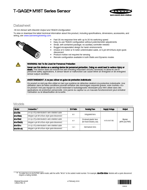
Datasheet18 mm Sensor with Discrete Output and TEACH ConfigurationTo view or download the latest technical information about this product, including specifications, dimensions, accessories, and wiring, see .•Fast 25 ms response time with up to 20 Hz switching speed•Easy-to-use TEACH configuration without potentiometer adjustments •Small, self-contained package; no auxiliary controller needed •Rugged encapsulated design for harsh environments•Choice of 2 meter or 9 meter unterminated cable, or 5-pin M12/Euro-style quick disconnect•Product motion not required for sensing•Remote configurationavailable in both Static and Dynamic modesWARNING: Not To Be Used for Personnel ProtectionNever use this device as a sensing device for personnel protection. Doing so could lead to serious injury or death. This device does not include the self-checking redundant circuitry necessary to allow its use inpersonnel safety applications. A sensor failure or malfunction can cause either an energized or de-energizedsensor output condition.AVERTISSEMENT: A ne pas utiliser en guise de protection individuelleCe produit ne doit pas être utilisé en tant que système de détection destiné à la protection individuelle. Une utilisation dans de telles conditions pourrait entraîner des dommages corporels graves, voire mortels.</b>Ce produit n'est pas équipé du circuit redondant d'autodiagnostic nécessaire pour être utilisé dans desapplications de protection personnelle. Une panne du capteur ou un mauvais fonctionnement peut entraîner l'activation ou la désactivation de la sortie.ModelsT-GAGE ® M18T Series SensorOverviewThe T-GAGE analog sensor is a passive, non-contacting, temperature-based device. It is used to detect objects that are either hotter or colder than the ambient condition and then activate an output.While it looks and operates just like an Expert™ photoelectric sensor, the T-GAGE detects the infrared light energy emitted by objects, instead of its own emitted light. The sensor uses a thermopile detector, made up of multiple infrared-sensitive elements (thermocouples) to detect this infrared energy within its field of view (see Figure 2 on page 3). Potential applications include:•Hot part detection (baked goods, metals, bottles)•Ejection verification of injection-molded parts•Flame process verification•Hot glue detection (packaging equipment, book binding)•Cold part detection (frozen foods, ice, dairy)•Roller monitoringFigure 1. Sensor Features 1.Power LED2.Alarm Output LED3.Push Button Note: The T-GAGE M18T sensor is not intended for absolute temperature measurement or for safety-related firedetection use.Note: Le T-GAGE M18T n'est pas conçu pour une mesure de température absolue ni pour une utilisation dans lecadre de sécurité pour la détection de feu.IndicatorsSensing Field of ViewSensing range is determined by the sensor’s field of view or viewing angle, combined with the size of the object(s) being detected. See Figure 2 on page 3. The sensor’s distance-to-spot size ratio (D:S ratio) is inversely related to the viewing angle; a sensorwith a small viewing angle will have a large D:S ratio. The T-GAGE M18T sensors have D:S ratios of 6:1, 8:1 or 14:1. For a sensor with an 8:1 D:S ratio, the sensor spot size is a 1" diameter circle at a distance of 8"; farther from the sensor face the spot size will be larger.Figure 2. Detection spot size versus distance from sensorApparent TemperatureTwo factors that have a large influence on apparent temperature are the object’s emissivity and whether or not the object fills the sensor field of view.Object EmissivityA “blackbody” is a “perfect” emitter, with an emissivity of 1.0 at all temperatures and wavelengths. Most surfaces emitonly a fraction of the amount of thermal energy that a blackbody would. Typical T-GAGE applications will be sensing objects with emissivities ranging from 0.5 to 0.95. Many references are available with tables of emissivity coefficients for common materials. In general, shiny unpainted metals have low emissivity, while non-glossy surfaces have highemissivity.Shiny SurfacesA mirror or shiny surface can redirect an object’s emitted energy to an undesired location, or even bring additionalunintended thermal energy into the sensor’s field of view. See Application Note on page 7.Object SizeIf the object being detected does not fill the sensor field of view, then the sensor averages the temperature of that object and whatever else is in the sensing field of view. For the sensor to collect the maximum amount of energy, the object should completely fill the sensor field of view. In some applications, when the object is too small, this may not be possible.In such cases, if the object is hot enough, the thermal contrast may still be adequate to trigger the sensor output. InstallationInstallation NoteAlign the sensor toward the object to be detected. Visually align if possible, or use the alignment device accessory listed in Additional Accessories on page 8.Wiring DiagramNote: Cabled wiring diagrams arefunctionally identical.Note: Connect the shield wire to earthground or dc common. Shielded cordsetsare recommended for all quick disconnectmodels.Sensor ConfigurationConfigure the sensor using one of two TEACH methods:•Two-Point Static TEACH•Dynamic TEACHUse the push button or remote input to configure the sensor.Note: The duration of each remote line pulse (corresponding to a push button “click”), and the period betweenmultiple pulses, are defined as “T”: 0.04 seconds < T < 0.8 seconds.Push Button Enable/DisableThe push button can be disabled using the remote input wire (gray) to prevent unauthorized adjustment. To disable the push button, connect a normally open switch between the remote input wire and dc common or connect the remote input wire to a digital output on PLC. Perform the procedure below to enable or disable the push button.2-Point Static TEACHUse 2-Point Static TEACH configuration method for applications where both ON and OFF target conditions can be presented to the sensor statically by the operator. The sensor establishes a single sensing threshold (the switchpoint) midway between the two configured conditions, with the Output ON condition on one side and the Output OFF condition on the other.Note: The sensor returns to RUN mode if the first 2-Point Static TEACH condition is not configured within 60seconds.Note: After the first condition is configured, the sensor remains in 2-Point Static TEACH configuration until the second condition is configured.1.Access 2-Point Static TEACH configuration.2.Present the output ON condition.3.Present the output OFF condition.Note: To exit 2-Point Static TEACH configuration without saving a configuration, press and hold the push buttonfor 2 seconds or hold the remote line for 2 seconds. The sensor will return to Run mode without saving aconfiguration.Dynamic TEACHUse Dynamic TEACH configuration method for applications where both the ON and OFF target conditions can not be presented to the sensor dynamically by the operator. After the configuration has been completed, the threshold at the midpoint is optimized by the sensor halfway between the average signals presented during the Dynamic TEACH configuration.1.Access Dynamic TEACH configuration.2.Present the sensing conditions.3.End Dynamic TEACH configuration.Hot Operate/Cold Operate SelectConfigure the sensor for Hot Operate, or Cold Operate using the remote input wire (gray). Pulse the remote line three times to toggle between Hot and Cold Operate.SpecificationsTemperature Measurement Range 0 °C to +300 °C (+32 °F to +572 °F)Custom ranges available upon requestSensing RangeDepends on object size and sensing field of view (see Sensing Field of View on page 2)Wavelength8 µm to 14 µmDistance to Spot Size (D:S) Ratio6:1, 8:1, or 14:1, depending on model Supply Voltage10 V dc to 30 V dc (10% maximum ripple)35 mA maximum (exclusive of load)Output ConfigurationOne NPN and one PNP in each model Output ProtectionProtected against short-circuit conditionsOutput Ratings100 mA maximum (each output)OFF-state leakage current: NPN < 200 microamps; PNP < 10 microamps NPN saturation: < 200 mV at 10 mA and < 1 V at 100 mA PNP saturation: < 1.2 V at 10 mA and < 1.6 V at 100 mA Delay at Power-Up 1.5 seconds Output Response Time25 msRepeatability (Relative)1 °C Minimum Taught Differential 3 °CHysteresis5% of taught differential (minimum 1 °C)AdjustmentsTEACH configurationIndicatorsOne bicolor (Green/Red) status LED, one Amber LED (see Indicators on page 2)Remote Teach Input Impedance: 3 kΩConstructionThreaded Barrel: 304 stainless steel Push Button Housing: ABS/PC Push Button: Santoprene Lightpipes: Acrylic Operating Conditions–20 °C to +70 °C (–4 °F to +158 °F)Environmental RatingLeakproof design rated IEC IP67; NEMA 6Temperature Warm-Up Time 5 minutes CertificationsClass 2 powerRequired Overcurrent ProtectionWARNING: Electrical connections must bemade by qualified personnel in accordance with local and national electrical codes and regulations.Overcurrent protection is required to be provided by end product application per the supplied table.Overcurrent protection may be provided with external fusing or via Current Limiting, Class 2 Power Supply.Supply wiring leads < 24 AWG shall not be spliced.For additional product support, go to .Protection contre la surintensité requiseAVERTISSEMENT: Les raccordements électriques doivent être effectués par du personnel qualifié conformément auxréglementations et codes électriques nationaux et locaux.Une protection de surintensité doit être fournie par l'installation du produit final, conformément au tableau fourni.Vous pouvez utiliser un fusible externe ou la limitation de courant pour offrir une protection contre la surtension dans le cas d'une source d'alimentation de classe 2.Les fils d'alimentation < 24 AWG ne peuvent pas être raccordés.Pour obtenir un support produit supplémentaire, rendez-vous sur le site .Application NoteThe following are examples of materials with high and low emissivity. Additional examples can be found online.•Asphalt•Brick•Carbon - lampblack or plate material •Cardboard - corrugated or chipboard •Concrete•Glass - smooth, lead, or borosilicate(e.g., Pyrex®)•Gypsum (including finished boards)•Iron and steel (except brightgalvanized)•Paper - most types, regardless ofcolor•Styrofoam® insulation•Plastics•Water•Wood - most types•Copper•Galvanized iron•Stainless steel•Vapor-deposited materialsDimensions(0.42")**Overall LengthModel M18T..8Q 91.3 mm (3.59")Model M18T..6EQ 91.8 mm (3.61")Model M18T..14Q 96.6 mm (3.80") *Overall LengthModel M18T..8 81.2 mm (3.20")Model M18T..6E 81.7 mm (3.22")Model M18T..14 86.5 mm (3.41")AccessoriesCordsetsBracketsAdditional AccessoriesLaser Alignment Tool - LAT1812•Enables easy sensor alignment at long distances.•Kit includes one SMB1812 bracket and M12 laser emitter.•Thread bracket housing onto barrel of mounted sensor; M12 laser emitter inserted into housing provides a precise laser spot for aiming temperature sensor. (Refer to Banner data sheet p/n 122529 for more information.)•Remove laser emitter before using sensor.SMB1812 BracketM12 Laser EmitterShown with T-GAGE M18T attachedBanner Engineering Corp. Limited WarrantyBanner Engineering Corp. warrants its products to be free from defects in material and workmanship for one year following the date of shipment. Banner Engineering Corp. will repair or replace, free of charge, any product of its manufacture which, at the time it is returned to the factory, is found to have been defective during the warranty period. This warranty does not cover damage or liability for misuse, abuse, or the improper application or installation of the Banner product.THIS LIMITED WARRANTY IS EXCLUSIVE AND IN LIEU OF ALL OTHER WARRANTIES WHETHER EXPRESS OR IMPLIED (INCLUDING, WITHOUT LIMITATION, ANY WARRANTY OF MERCHANTABILITY OR FITNESS FOR A PARTICULAR PURPOSE), AND WHETHER ARISING UNDER COURSE OF PERFORMANCE, COURSE OF DEALING OR TRADE USAGE.This Warranty is exclusive and limited to repair or, at the discretion of Banner Engineering Corp., replacement. IN NO EVENT SHALL BANNER ENGINEERING CORP. BE LIABLE TO BUYER OR ANY OTHER PERSON OR ENTITY FOR ANY EXTRA COSTS, EXPENSES, LOSSES, LOSS OF PROFITS, OR ANY INCIDENTAL, CONSEQUENTIAL OR SPECIAL DAMAGES RESULTING FROM ANY PRODUCT DEFECT OR FROM THE USE OR INABILITY TO USE THE PRODUCT, WHETHER ARISING IN CONTRACT OR WARRANTY, STATUTE, TORT,STRICT LIABILITY, NEGLIGENCE, OR OTHERWISE.Banner Engineering Corp. reserves the right to change, modify or improve the design of the product without assuming any obligations or liabilities relating to any product previouslymanufactured by Banner Engineering Corp. Any misuse, abuse, or improper application or installation of this product or use of the product for personal protection applications when the product is identified as not intended for such purposes will void the product warranty. Any modifications to this product without prior express approval by Banner Engineering Corp will void the product warranties. All specifications published in this document are subject to change; Banner reserves the right to modify product specifications or update documentation at any time. Specifications and product information in English supersede that which is provided in any other language. For the most recent version of any documentation, refer to: .For patent information, see /patents .。
18KW级光电传感器系列用户指南说明书

Photoelectric SensorsTubular2.30Combination 18 mm threaded90º opticsBOS 18KW-PA-1XA-S4-C BOS 18KW-NA-1XA-S4-C BOS 18KW-PA-1N1R-S4-C BOS 18KW-NA-1N1R-S4-C BOS 18KW-PA-1QC-S4-C BOS 18KW-NA-1QC-S4-CBOS 18KW-PA-1TB-S4-C BOS 18KW-NA-1TB-S4-C BLE 18KW-PA-1PP-S4-C BLE 18KW-NA-1PP-S4-C BLS 18KW-XX-1P-S4-LCombination 18 mm threaded90º opticsBOS 18KW-PA-1PD-C-02BOS 18KW-NA-1PD-C-02BOS 18KW-PA-1XA-C-02BOS 18KW-NA-1XA-C-02BOS 18KW-PA-1N1R-C-02BOS 18KW-NA-1N1R-C-02BOS 18KW-PA-1QC-C-02BOS 18KW-NA-1QC-C-02BOS 18KW-PA-1TB-C-02BOS 18KW-NA-1TB-C-02BLE 18KW-PA-1PP-C-02BLE 18KW-NA-1PP-C-02BLS 18KW-XX-1P-L-02Body Style TypeLong Range Diffuse (L 1)PNP NO+NC Light-on 400 mm 270° Pot.NPN NO+NC Light-on 400 mm 270° Pot.Short Range Diffuse (L 2)PNP NO+NC Light-on 80 mm NPN NO+NC Light-on 80 mm Fixed Focus (L 2)PNP NO+NC Light-on 80 mm NPN NO+NC Light-on 80 mm Polarized Retroreflective (L 1)PNP NO+NC Dark-on 3 m 270° Pot.NPN NO+NC Dark-on 3 m 270° Pot.Transparent Detection Retroreflective (L 1)PNP NO+NC Dark-on 1.7 m 270° Pot.NPN NO+NC Dark-on 1.7 m 270° Pot.Thru-beam (L 1)PNP NO+NC Dark-on 10 m Receiver 270° Pot.NPN NO+NC Dark-on 10 m Receiver 270° Pot.Emitter (L 2)Supply Voltage RippleVoltage Drop U d at I eRated Output Current I eCurrent Consumption I O (No Load)Utilization Category (IEC 60-947-4-1) Output Duty Cycle Emitter Light SourceLight Spot DiameterAmbient Light Immunity (EN 60947-5-2)Power Indicator Output IndicatorStability/Error Indicator Switching Frequency fResponse Time (On/Off Delay)OperatingT emperature Range Electrical Shock ProtectionDegree of Protection per IEC 60529Short Circuit Protection Overload Protection Housing MaterialSensing Face Material Emitter Life ConnectionLong Range Diffuse Short Range Diffuse Fixed Focus Polarized Transparent Thru-beam10…30 Vdc < 10%< 2 V 100 mA < 30 mA DC 13Visible Red 630 nm Fixed Focus/Infrared 880 nm Diffuse35 mm @ 400 mm 55 mm @ 100 mm 25 mm @ 80 mm 60 mm @ 2 m 60 mm @ 1 m 470 mm @ 10 m5000 LuxGreen LED (Emitter Only)Yellow LED (Except Emitter)Green/Red LED250 Hz Thru-beam, 1 kHz Diffuse/Fixed Focus/Retroreflective < 2 ms Thru-beam, < 0.5 ms Diffuse/Fixed Focus/Retroreflective-25°C to +55°CClass 2IP 67Yes Yes PBT PMMAAverage 100,000 hr with Ta=+25°CM12 4-pin connector Cable 2 m, PVC, 4 x 26 AWG BOS 18KWqN wN qO wO qP wP qQ wQ qR wR qS wS eSC o u r t e s y o f C M A /F l o d y n e /H y d r a d y n e ▪ M o t i o n C o n t r o l ▪ H y d r a u l i c ▪ P n e u m a t i c ▪ E l e c t r i c a l ▪ M e c h a n i c a l ▪ (800) 426-5480 ▪ w w w .c m a f h .c o mTubularBody StyleTypeBackground Suppression (BGS)PNP NO+NC Light-on 50...100 mm T each-inNPN NO+NC Light-on 50...100 mm Teach-inSupply VoltageRippleVoltage Drop U d at I eRated Output Current I eCurrent Consumption I O (No Load)Utilization Category (IEC 60-947-4-1) Output Duty Cycle Emitter Light SourceLight Spot DiameterAmbient Light Immunity (EN 60947-5-2)Output IndicatorStability/Error IndicatorSwitching Frequency fResponse Time (On/Off Delay)Operating Temperature RangeElectrical Shock ProtectionDegree of Protection per IEC 60529Short Circuit ProtectionOverload ProtectionHousing MaterialSensing Face MaterialEmitter LifeConnectionRecommended ConnectorWeightqMwMq = Number indicates wiring diagramA = Letter indicates detection diagramSee pages 2.34-2.35 for diagramsCourtesyofCMA/Flodyne/Hydradyne▪MotionControl▪Hydraulic▪Pneumatic▪Electrical▪Mechanical▪(8)426-548▪www.cmafh.co m。
CA18CLF08和CA18CLN12传感器的产品说明说明书

Specifications are subject to change without notice (17.08.2018)1Type SelectionProduct DescriptionProximity Sensors Capacitive Thermoplastic Polyester Housing Type CA, M18, AC• Featuring TRIPLESHIELD ™ sensor protection• Rated operational voltage: 20-250 VAC• Adjustable sensing distance 3-8 mm or 3-12 mm • Output: SCR• Make or break switching function • LED indication• High noise immunity• Flush and non-flush types • Plug and cable versions• DC versions in the same housingCapacitive proximity switc h e s with either sensing distance 8 mm flush mounted in metal or sensing distance 12 mm non-flush mounted. 2-wire AC output with ma k e (NO) or bre-ak (NC) switch i ng. Grey M 18polyester housing with 2 m PVC cable or M12 plug. Ideal for use in level and plas t ic ma c hin e ry applica t ions.Housing Rated Mounting Ordering no. Ordering no. Ordering no. Ordering no.diameter operating S CR/cable S CR/plug S CR/cable S CR/plug dist. (S n ) 1) MakeMakeBreakBreak switchingswitchingswitchingswitchingM18 8 mm Flush (built-in) CA18CLF08TO CA18CLF08TOM6 CA18CLF08TCCA18CLF08TCM6M1812 mmNon-flush CA18CLN12TO CA18CLN12TOM6 CA18CLN12TCCA18CLN12TCM61)Object: Grounded steel plateSpecificationsT R I P L E SH I E L D ™2Specifications are subject to change without notice (17.08.2018)Wiring DiagramsEC, M18, ACThe environments in which capacitive sensors are install-ed can often be un s table re-garding temperature, humi d ity , object distance and industrial (noise) interference. Because of this, Carlo Ga v azzi offers as standard features in allTRIP L ESHIELD ™ capacitive sensors a user-friendly sen-sitivity adjustment instead of having a fixed sensing range, extend e d sen s ing range todemand i ng are a s, temperatu-re stability to en s ure minimum need for adjusting sensitivity if temperature varies and high immunity to elec t ro m agnetic interference (EMI).Note:Sensors are factory set (de-fault) to maximum rated sen-sing range.Adjustment GuideInstallation HintsCapacitive sensors have the unique ability to detect al-most all materials, either in li-quid or solid form. Capa c i t ive sensors can detect metallic as well as non-metallic ob-jects, how e ver, their traditi-onal use is for non-metallic materials such as:• Plastic IndustryResins, regrinds or moul-ded products.• Chemical IndustryCleansers, fertilisers, liquid soaps, corrosives and pe-trochemicals.• Wood IndustrySaw dust, paper products, door and window frames.• Ceramic & Glass I ndustryRaw material, clay or finish-ed products, bottles.• Packaging Industry Pac-kage inspection for level or contents, dry goods, fruits and vegetables, dairy pro-ducts.M aterials are detected due to their dielectric constant. The bigger the size of an object, the higher the den-sity of material, the better or easier it is to detect the object. Nominal sensing di-stan c e for a capacitive sen-sor is referenced to a groun-ded me t al plate (ST37). For addi t ional information regarding di e lec t ric ratings of materials please re f er toTechnical Information.DimensionsCA18CLxxxTC CA18CLxxxTOBU (2)BU (2)BN (3)BN (3)Relief of cable strainProtection of the sensing faceSwitch mounted on mobile carrierTo avoid interference from inductive voltage/ current peaks, separate the prox. switch pow-er cables from any other power cables, e.g. motor, contactor or solenoid cablesIncorrectCorrectThe cable should not be pulledA proximity switch should not serve as mechanical stopAny repetitive flexing of the cable should be avoidedDelivery Contents •Capacitive switch: CA18CL...• Screw driver• 2 nuts• Packaging: Cardboard box • Installation & Adjustment Guide Accessories• Plugs CON.6A-..series.EC, M18, ACSpecifications are subject to change without notice (17.08.2018) 3。
光纤传感器产品介绍说明书

TEACH
Teaching
The “threshold value” can be set by utilizing either “2-point teaching”, “limit teaching”, or “full-auto teaching”.
* When the FX-305(P) is in window comparator mode, the “threshold value” can be set by either “1-point
LASER SENSORS
Diagram of functions and settings
PHOTOELECTRIC SENSORS
MICRO PHOTOELECTRIC SENSORS
AREA SENSORS
LIGHT CURTAINS /
SAFETY COMPONENTS PRESSURE /
FA COMPONENTS MACHINE
VISION SYSTEMS
UV CURING SYSTEMS
Selection Guide Fibers Fiber
Amplifiers
FX-500 FX-100 FX-300 FX-410 FX-311 FX-301-F7/ FX-301-F
PRO2
Light Emitting Amount Selection Changes the light emitting amount selection setting. [FX-301(P)(-HS), FX-305(P) only]
● Stable sensing comparison
Even greater sensing range
S-FS-N 系列sensor放大器的使用
2.1.1 针对电缆类型接线图
1路输出型(仅FS-N11N/N11P) 2路输出型(仅FS-N13N/N13P)
监视器输出型(仅FS-N11MN)
连结至输入 阻抗大于 10K的设备
8
2.1.2 针对M8/e-CON连接器类型接线图
9
10
2.2 连接光纤模块
Ⅰ 若光纤是自由切割类型,请切 掉多余的部分 ①将光纤插入切断器孔中。 ②快速按下刀片,一次切断光纤。
25
菜单功能表与推荐光纤模块
26
3.6 初始化
传感器放大器可以重设为出厂默认设定。
Ⅰ同时按住SET和PRESET按钮保持3秒或 更长时间。 “rSt”显示并闪烁。 Ⅱ 按MODE按钮。 Ⅲ 按下手动按钮以显示“init”。 Ⅳ 按MODE按钮。 初始化设置后,画面显示“Ok”,随后 会替换为当前接收到的光强度。
设定值 为“50.0”
当前值设 为“100.0”
14
3.2.2 工作预设定功能
此功能会将当前值校正为“0”。在使用参数执“100” 执行预设定功能后,再使用“0”参数执行此功能,可将2 个随机设定点校准为“100.0”与“0”。 ◆启用工作预设定功能 启用预设定功能时,同时按下 PRESET和手动按钮(右)。 该点的接收光强度设为“0” 而利 用预设定功能为“100.0” ,值不会 变化。 ◆禁用工作预设定功能 PST 指示灯亮起时,请按住 PRESET按钮。 ● PST 指示灯熄灭时,表示工 作预设定功能已禁止。 当前 值为 “0”
17
3.2.5 两点校准
两点校准是灵敏度设定的最基本方法。只需在产品存在和不存在时 分别按SET按钮一次,即可建立设定值。 此时无 Ⅰ 产品不存在时按SET按钮一次。 产品 Ⅱ 产品存在时按SET按钮一次。 设定值即时闪烁后表示校准完成, 然后停止(灯亮)。 按手动按钮调整设定值。
fsn18n光纤传感器说明书

fsn18n光纤传感器说明书一、产品概述FSN18N光纤传感器是一种利用光纤作为传感元件,可以用于检测物体的存在、距离和位置的高精度传感器。
本传感器适用于工业自动化、机器人控制、流水线、包装等领域。
二、产品特点1.高精度:采用光纤作为传感元件,具有高灵敏度和高分辨率,可实现对小尺寸物体进行精确检测。
2.高可靠性:采用先进的光电技术,具有较高的抗干扰能力和稳定性,能稳定工作在恶劣的工业环境下。
3.多功能:传感器可通过调节参数实现对光斑大小、测距范围、输出方式等多种功能的配置,适应不同应用场景。
4.环保节能:采用低功耗设计,减少能源消耗,对环境友好。
三、技术参数1.输入电压:24VDC2.输出类型:PNP/NPN3. 探测距离:0-300mm4.工作温度:-20℃~70℃5.保护等级:IP676.光源:红外光7.光斑大小:可调节8.反馈时间:100μs9.材质:铝合金外壳四、产品安装1.在安装之前,请确保传感器与电源断开连接,防止电击。
2.将传感器底部的固定螺丝拧松,将其安装在所需位置上。
3.安装时请注意保持传感器与光纤精确对齐,并避免光纤弯曲或受力。
4.以逆时针方向旋转固定螺丝,固定传感器。
五、产品调试1.接通电源,传感器将进行自检程序,若指示灯亮起即表明传感器工作正常。
2.通过旋转光纤前端调节环来调节光斑的大小,使其适应检测对象。
3.调节光纤前端调节环实现检测距离的调节,确保距离范围满足要求。
4.根据需要,选择正确的输出方式,连接到相应的设备。
六、注意事项1.请勿将传感器暴露在高温或腐蚀性气体的环境中,以免影响传感器性能。
2.传感器安装时请注意避免强烈的震动和冲击,以免损坏设备。
3.安装和使用过程中请避免与硬物碰撞,以防光纤断裂。
4.使用过程中请定期对传感器进行清洁,以保持传感器的灵敏度和稳定性。
5.定期检查传感器的电源连接和固定状态,确保传感器正常工作。
七、售后服务。
沃斯科技 QS18 VN6AF300 编程传感器说明书
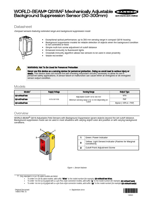
DatasheetCompact sensors featuring extended range and background suppression mode•Exceptional optical performance; up to 300 mm sensing range in compact QS18 housing•Background suppression models for reliable detection of objects when the background condition is not controlled or fixed•Simple multi-turn screw adjustment of cutoff distance •Enhanced immunity to fluorescent lights•Crosstalk immunity algorithm allows two sensors to be used in close proximity •Visible red emitterWARNING: Not To Be Used for Personnel ProtectionNever use this device as a sensing device for personnel protection. Doing so could lead to serious injury or death. This device does not include the self-checking redundant circuitry necessary to allow its use inpersonnel safety applications. A sensor failure or malfunction can cause either an energized or de-energized sensor output condition.ModelsOverviewWORLD-BEAM ® QS18 Adjustable-Field Sensors with Background Suppression ignore objects beyond the set cutoff distance.Background suppression mode can be used in most situations with varying object color and position or with varying backgroundconditions.31Green: Power Indicator2Yellow: Light Sensed Indicator (Flashes for Marginal Conditions)3Cutoff Point Adjustment ScrewFigure 1. Sensor features•To order 9 m (30 ft) cable models: add suffix “W/30” to the model number (for example, QS18VN6AF300 W/30).•To order 150 mm (6 in) pigtail with a 4-pin Pico-style connector models, add suffix “Q ” to the model number (for example, QS18VN6AF300Q )•To order 150 mm (6 in) pigtail with a 4-pin Euro-style connector models, add suffix “Q5” to the model number (for example,QS18VN6AF300Q5)WORLD-BEAM ® QS18AF Mechanically Adjustable Background Suppression Sensor (30-300mm)Original Document146923 Rev. G11 September 2018146923Sensor OrientationTo ensure reliable detection, orient the sensor as shown in relation to the target to be detected.Figure 2. Optimal Orientation of Target to SensorWiring DiagramsCabled wiring diagrams are shown.Quick disconnect (QD) wiring diagrams are functionally identical.NPN (Sinking) Outputs–+PNP (Sourcing) Outputs–+Wiring Key1 = Brown2 = White3 = Blue4 = BlackBipolar Outputs–+Sensor Setup - Background SuppressionBackground Suppression Mode: Objects beyond the set cutoff distance will not be detected.Background suppression mode can be used in most situations with varying object colors and positions or with varying background conditions.To ensure reliable background suppression, a minimum separation distance between the object and the background is necessary.See Figure 7 on page 5 to determine the minimum separation distance. - Tel: +1-763-544-3164P/N 146923 Rev. G1.Mount the sensor with the darkest object at the longestapplication distance. The distance to the object must be less than shown in Figure 7 on page 5 for your object color.2.Turn the adjustment potentiometer counter-clockwise until theyellow indicator turns off (5 turns maximum).3.Turn the adjustment potentiometer clockwise until the yellowindicator turns on.4.Replace the darkest object with the brightest background at theclosest application distance.5.Turn the adjustment potentiometer clockwise, counting therevolutions, until the yellow indicator turns on.6.Turn the adjustment potentiometer counter-clockwise half of thenumber of turns from step 5. This places the cutoff distancemidway between the object and the background switchpoints (see Figure 3 on page 3).The sensor is ready for operation.DistanceX: Distance to the ObjectY: Minimum Separation Between the Object and the BackgroundFigure 3.Set the cutoff distance approximately midway between the farthest object and the closest backgroundSetup ExampleAn object with a reflectivity similar to black paper is set 150 mm away from the sensor. A background with a reflectivity similar to white paper is set 200 mm away from the sensor. According to Figure 7 on page 5 , the minimum separation distance between the object and the background is 12 mm. In this application, reliable detection is achieved when set up according to the procedure outlined in Sensor Setup - Background Suppressionon page 2. Figure 4. Background Suppression Mode Application Example 1. Object2. Conveyor3. BackgroundX: Distance to the Object = 150 mmY: Minimum Separation Between the Object and the Background > 12 mmOutput StatesP/N 146923 Rev. G - Tel: +1-763-544-31643SpecificationsSupply Voltage10 to 30 V dc (10% maximum ripple within specified limits) at less than 16 mA, exclusive of load Sensing BeamVisible red LED, 640 nmSupply Protection CircuitryProtected against reverse polarity and transient voltagesOutput ConfigurationSolid-state complementary: NPN or PNP (current sinking or sourcing),or bipolar (both sinking and sourcing) depending on model;Rating: 100 mA total output currentOff-state leakage current: < 50 µA at 30 V dcON-state saturation voltage: < 1.5 V at 10 mA; < 3.0 V at 100 mAProtected against false pulse on power-up and continuous overload or short circuit of outputsRequired Overcurrent ProtectionWARNING: Electrical connections must be made by qualified personnel in accordance with local and national electrical codes and regulations.Overcurrent protection is required to be provided by end product application per the supplied table.Overcurrent protection may be provided with external fusing or via Current Limiting, Class 2 Power Supply.Supply wiring leads < 24 AWG shall not be spliced.For additional product support, go to .Output Response2.8 millisecond ON/OFFNote: 200 millisecond delay on power-up; outputs do not conduct during this time AdjustmentsFive-turn adjustment screw sets cutoff distance between min. and max.positions, clutched at both ends of travel Repeatability 250 µsIndicators2 LED indicators on sensor top:Green solid: Power on Amber solid: Light sensedAmber flashing: Marginal sensing conditionConstructionABS housing, acrylic lens cover; PVC cable, nickel-plated brass connector,acetal adjustment pot Environmental RatingIEC IP67; NEMA 6; UL Type 1Connections2 m (6.5 ft) 4-wire PVC cable, 9 m (30 ft) PVC cable, or 4-pin Pico-style or Euro-style 150 mm (6 in) pigtail QD, depending on model Operating ConditionsRelative Humidity: 95% relative humidity at 50 °C (non-condensing)Temperature: –20 °C to 55 °C (–4 °F to 131 °F)Application NotesFor mirror-like objects, minimize the sensor to object mounting distance and tilt the sensor so reflected light is directed away from the sensor when the object is present.CertificationsPerformance CurvesQS18AF300 Minimum Sensing Range vs. 90% White Cuttoff Setting0510155010015020025030035090% White Card Cutoff Setting (mm)M i n i m u m S e n s i n g R a n g e (m m ) f o r 6% B l kFigure 5. Minimum Sensing Range (Dead Zone) vs. 90% White Cutoff Setting510152025050100150200250300350Range (mm)E m i t t e r S p o t D i a m e t e r (m m )Figure 6. Typical Emitter Spot Diameter vs. Distance - Tel: +1-763-544-3164P/N 146923 Rev. GExcess Gain Curves1101001000DISTANCE (mm)E X C E S S G A I N1101001000Figure 8. Excess Gain Curve with 30 mm Cutoff (based on 90% White Card)1101001000DISTANCE (mm)E X C E S S G A I N1101001000Figure 9. Excess Gain Curve with 300 mm Cutoff (based on 90% White Card)P/N 146923 Rev. G - Tel: +1-763-544-31645DimensionsAll measurements are listed in millimeters [inches], unless noted otherwise.7.5 mm(0.30")15.0 mm*M3 Hardware for SidemountM2.5 Hardware for Mountingto Threaded InsertsMax. torque 0.6 nm (5 in. lbs)(2) M3 x 0.5 x 20 mm ss screw(2) M3 x 0.5 ss hex nut(2) M3 ss washer(2) M2.5 x 0.45 x 5 mm ss screw(2) M2.5 ss washerAccessoriesQuick-Disconnect (QD) Cordsets - Tel: +1-763-544-3164P/N 146923 Rev. GMounting BracketsAll measurements are listed in millimeters, unless noted otherwise. SMBQS18A•Wrap-around protectionbracket•Die-cast bracket•Base fits 18 mm threadedhole•Metal hex nut, lock washerand grommet included•Mounting holes speciallydesigned for QS18AFsensorsHole size: A = ø 15.3SMBQS18AF•Right-angle mountingbracket•14-ga. 304 stainless steel Hole center spacing: A to B = 20.3 Hole size: A = 4.3 × 9.4, B = ø 4.3Banner Engineering Corp. Limited WarrantyBanner Engineering Corp. warrants its products to be free from defects in material and workmanship for one year following the date of shipment. Banner Engineering Corp. will repair or replace, free of charge, any product of its manufacture which, at the time it is returned to the factory, is found to have been defective during the warranty period. This warranty does not cover damage or liability for misuse, abuse, or the improper application or installation of the Banner product.THIS LIMITED WARRANTY IS EXCLUSIVE AND IN LIEU OF ALL OTHER WARRANTIES WHETHER EXPRESS OR IMPLIED (INCLUDING, WITHOUT LIMITATION, ANY WARRANTY OF MERCHANTABILITY OR FITNESS FOR A PARTICULAR PURPOSE), AND WHETHER ARISING UNDER COURSE OF PERFORMANCE, COURSE OF DEALING OR TRADE USAGE. This Warranty is exclusive and limited to repair or, at the discretion of Banner Engineering Corp., replacement. IN NO EVENT SHALL BANNER ENGINEERING CORP. BE LIABLE TO BUYER OR ANY OTHER PERSON OR ENTITY FOR ANY EXTRA COSTS, EXPENSES, LOSSES, LOSS OF PROFITS, OR ANY INCIDENTAL, CONSEQUENTIAL OR SPECIAL DAMAGES RESULTING FROM ANY PRODUCT DEFECT OR FROM THE USE OR INABILITY TO USE THE PRODUCT, WHETHER ARISING IN CONTRACT OR WARRANTY, STATUTE, TORT, STRICT LIABILITY, NEGLIGENCE, OR OTHERWISE.Banner Engineering Corp. reserves the right to change, modify or improve the design of the product without assuming any obligations or liabilities relating to any product previously manufactured by Banner Engineering Corp. Any misuse, abuse, or improper application or installation of this product or use of the product for personal protection applications when the product is identified as not intended for such purposes will void the product warranty. Any modifications to this product without prior express approval by Banner Engineering Corp will void the product warranties. All specifications published in this document are subject to change; Banner reserves the right to modify product specifications or update documentation at any time. Specifications and product information in English supersede that which is provided in any other language. For the most recent version of any documentation, refer to: .© Banner Engineering Corp. All rights reserved。