OXYMAT 6 氧气分析仪-2014
OXME-P氧量分析仪和氧量分析仪价格

标题:OXME-G氧量分析仪
OXME-G型氧量分析仪产品描述OXME-G型氧量分析仪为在线式氧量分析仪,用于在正压力下测量洁净、干燥和非腐蚀性气体中氧气的浓度。广范适用于空分、石油化工、冶金、电子电力、机械制造及其它行业中的各种气体中氧含量的分析。仪器特点采用320*240LCD显示器台式或盘装,安装方便简单。采用进口离子流、电化学传感器,寿命长、灵敏度高、响应速度快。自带精密过滤器,大大提高传感器寿命。全量程自动温度补偿,测量准确度高。可在全量程范围内任意设置上下限控制点。具备数据备份、数据恢复功能。标准4-20mA或0-5V输出。选配标准RS232/RS485通信。方便的人机对话界面,直观的中文操作菜单。技术参数测量范围:0~10/100/1000ppm 0~0.5/5/25/100%(量程任选)精...
厂家:南北仪器
市场Байду номы氧量分析仪价格
OXME-P氧量分析仪
标题:OXME-P氧量分析仪
OXME-P型氧量分析仪产品描述OXME-P型氧量分析仪为便携式氧量分析仪,用于在正压力下测量洁净、干燥和非腐蚀性气体中氧气的浓度。广范适用于空分、石油化工、冶金、电子电力、机械制造及其它行业中的各种气体中氧含量的分析。仪器特点采用128*64LCD显示器。采用进口离子流、电化学传感器,寿命长、灵敏度高、响应速度快。采用独特内置保护气路,有效保护传感器因长时间暴露于空气中而影响传感器寿命。配备有大容量长寿命锂电池,界面电量显示,电路电压保护。充电电池一次充电可连续工作12小时以上。具备数据备份、数据恢复功能。方便的人机对话界面,直观的中文操作菜单。仪器内置进口抽气泵(可选配)。技术参数测量范围:0~10/100/1000ppm 0~0.5/5/25/100%(...
WITT OXYBABY Med 氧气分析仪说明书

222O X Y 3 U S A - Q 02/3F s u b j e c t t o c h a n geCordless hand held analyser for checking medical gases.OXYBABY ® Med from WITT is the ideal instrument for portable, faster and accurate tests at gases before application in hospitals - for protection of patients.After connect on the OXYBABY ® Med at outlet point the measuring starts and the result is shown in the illuminated display.Not only kind of gas but also concentration and pressure are checked.Design and material of OXYBABY ® Med are hygienic optimised.Easy operation by intuitive operational concept.Logging of the last 500 measurements for documentation and export.For various connections an optional set of adapter is available.Bene fi ts●integrated data log of the last 500 measurements●product administration up to 25 users, 100applications and 50 allocations●increased memory capacity and simpli fi ed data ex-port of measurement results by microSD card ●cordless operation using rechargeable batteries ●data transfer and charge of batteries via USB port ●sample fl ow control with warning ●upgraded simple one-hand operation ●easy to clean●large illuminated graphic display ●multilingual menu guide: see overleaf ●long lifetime of O 2 sensor(approx. 2 years, depending on use)●low maintenance costsComplete in carrying case●charging device, microSD card●OBCC software (demo version) for downloading ●case dimensions (HxWxD):approx. 12.79 x 15.16 x 4.53 inches,case weight: approx. 3.75 lbOptions ●data cable●set of adapter for various connections ●Bluetooth (e.g. for separate printer)Please note our variety of accessories on the following pages!►Videofurther information onSet of adapter Order-No.according to DIN 956980100according to AFNOR 956980200according to UNI 956980300according to BS956980400OBCC So ware for gas analyzer OXYBABY® / PAC C 2 U S A - A 02/3F s u b j e c t t o c h a n g eSystem requirements Operating system WINDOWS ® 7 or aboveHardware1 free USB interface, graphic resolution min. 1024 x 768 PixelWindows-Software for OXYBABY ® 6.0, OXYBABY ® P 6.0,OXYBABY ® Med and PA 7.0.OBCC is the ideal complement for your WITT-Gas analyzer - with modern surface, clearly structured and conveniently operable.The application o ff ers rapid graphical analysis of measured values. Simplify a system comprehensive data management and o ff ers an uncomplicated export function for thecomplete digital storage.Bene fi ts●modern, clearly structured user interface ●intuitive operation●simple set up and administration of master data (products, user, packaging lines)●quality control by means of data recording and storing with date and time ●the graphical presentation of measured values o ff ers a fast overview ●knowledge by data analysis tool with fi lter options●completely digital documentation by simple CSV export function●1 click generate PDF report for assurance of proof (in addition to the CSV export)●time-saving by convenient data management and easy transfer of master data to new devices●available menu languages: English, German, French, Italian, Spanish, Portuguese, Polish, Russian, Finnish, Swedish,Turkish, Romanian, Hungarian30-day trial version with full function for download on 。
西门子OXYMAT 6 型氧气分析仪
• 用于维护和服务信息的 SIPROM GA 网络 ( 可选 )
• 电气部分和物理特性:气密隔离,可以吹扫, IP65,即使在恶 劣的环境中也可有很长的使用寿命
• 带加热型 ( 可选 ),也可在低温下有冷凝气体的情况下使用
• 防爆等级 EEx(p),用于 1 区和 2 区,符合 ATEX 2G 和 ATEX 3G
现场式 • 2 扇门式机箱,分析仪的分析部分和电子部分做到气密隔离 • 左,右机箱可分别吹扫 • 分析部分及其管线可最高加热到 130 °C ( 可选 ) • 气路和管线接头材质为不锈钢 ( 型号:1.4571) 或钽 • 吹扫气连接:管径为 10 mm 或 3/8" • 样气输入和输出处及参比气的气连接:用于管径为 6mm 或 1/4"
50 ~ 300 kPa 绝压
50 ~ 150 kPa 绝压 50 ~ 130 kPa 绝压 18 ~ 60 l/h (0.3 ~ 1 l/min) 0 ~ 50 °C < 90% 相对湿度 比样气压力高 200 ~ 400 kPa,最 高可达 500 kPa
环境温度下,< 30 分钟 ( 两小时以 后达到最高精度 ) 1.5~3.5 s ( 与机型有关 ) 0 ~ 100 s,可编程 大约 0.5 ~ 2.5 s ( 与机型有关 )
由于在测量地点存在振动并可能因此产生测量误差 ( 噪音 )。所以 可额外增加一个传感器 (10) 来作为振动传感器。该传感器中不通 过气体,其信号可用来对测量结果进行补偿。
如果样气密度和参比气密度偏差超过参比气密度的 50%,则用于 补偿的微流量传感器 (10) 也必须象用于测量的微流量传感器 (4) 一样通入参比气。
分析仪OXYMAT6
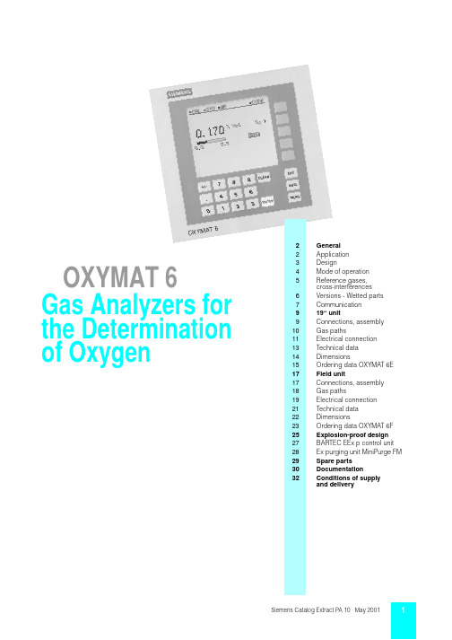
2General 2Application 3Design4Mode of operation 5Reference gases,cross-interferences 6Versions - Wetted parts 7Communication 919“unit9Connections, assembly 10Gas paths11Electrical connection 13Technical data 14Dimensions15Ordering data OXYMAT 6E 17Field unit17Connections, assembly 18Gas paths19Electrical connection 21Technical data 22Dimensions23Ordering data OXYMAT 6F 25Explosion-proof design 27BARTEC EEx p control unit 28Ex purging unit MiniPurge FM 29Spare parts 30Documentation32Conditions of supply and deliveryOXYMAT 6Gas Analyzers for the Determination of OxygenOXYMAT 6 GeneralThe OXYMAT 6 gas analyzers are based on the paramagnetic alternating pressure method and are used to measure oxygen in gases.Application examplesMeasurement of O2•For boiler control in firing systems•In safety-relevant areas•As a reference variable for emission measurements according to TA-Luft, 13. and 17. BImSchV•In the automotive industry (engine test systems)•Warning equipment•In chemical plants•In ultra-pure gases for quality monitoring•Version to analyze flammable and non-flammable gases or va-pors for use in hazardous areas (zone 1 and zone 2). (Use in hazardous areas of zone 0 is not permissible.)Special characteristics•Four freely-parameterizable measuring ranges, also with zero offset, all measuring ranges linear•Electrically isolated signal output selectable as 0/2/4 to 20 mA (also inverted)•Autoranging or manual range switching possible; remote switching is also possible•Storage of measured values possible during adjustments •Time constants selectable within wide limits (static/dynamic noise suppression); i.e. the response time of the analyzer can be matched to the respective application•Simple handling using menu-based operation•Short response time•Low long-term drift•Two-stage access code to prevent unintentional and unautho-rized inputs•Internal pressure sensor for correction of pressure variations in sample gas (range 500 to 2000 hPa absolute)•External pressure sensor can be connected for correction of variations in sample gas pressure (up to 3000 hPa absolute), only with piping as the gas path•Automatic range calibration can be parameterized •Operation based on NAMUR Recommendation •Monitoring of sample gas and/or reference gas (option)•Field bus connection (option)•Monitoring of reference gas with reference gas connection 2000 to 4000 hPa (option)•Different smallest spans (0.5 %, 2.0 % or 5.0 % O2), depending on version•Customer-specific analyzer options such as e.g.:-Customer acceptance-Tag labels-Drift recording-Clean for O2 service-Kalrez gaskets•Analyzer section with flow-type compensation circuit (option): a flow is passed through the compensation branch to reduce the vibration dependency in the case of highly different densi-ties of the sample and reference gases•Simple analyzer exchange since electric connections are easy to remove.19“ unit: special characteristics•19“ unit with 4 HU for installation in swing frame•19“ unit with 4 HU for installation in cabinets, with or without slide rails•Front panel for service can be hinged down(laptop connection)•Internal pressure sensor for correction of pressure variations in sample gas•Internal gas paths: flexible tube made of Viton or pipe made of titanium•Gas connections for sample gas input and output and for ref-erence gas: pipe diameter 6 mm or 1/4"•Sample chamber – with or without flow-type compensation branch – made of stainless steel (type No. 1.4571) or tantalum for highly corrosive sample gases (such as HCl, Cl2, SO2, SO3, etc.).Field unit: special characteristics•Two-door housing with-Gas-tight separation of analyzer and electronics sections (can also be purged separately if necessary)•Analyzer section and piping can be heated up to 130 °C (option)•Gas path and pipe couplings made of stainless steel (type No.1.4571) or titanium•Purging gas connections: pipe diameter 10 mm or 3/8".OXYMAT 6GeneralInputs and outputs•Six binary inputs freely configurable (e.g. for range switching, processing external signal from sample conditioning)•Six relay outputs freely configurable (failure, maintenance re-quest, maintenance switch, limit alarm, external solenoid valves)•Two analog inputs programmable (correction of cross-interfer-ences, external pressure sensor)•Extension with eight additional binary inputs and eight addi-tional relay outputs for automatic calibration with up to four cal-ibration gasesCommunication•RS 485 present in basic unit (connection at the rear; with 19“ unit also possibility of connection behind the front plate)Options•AK interface for the automotive industry with extended func-tions•Converter to RS 232•Linking to networks via PROFIBUS-DP/-PA interface •SIPROM GA software as service and maintenance toolDisplay and control panel•Large LCD panel for simultaneous display of:-Measured value (digital and analog displays)-Status line-Measuring ranges•Contrast of LCD panel adjustable using menu •Permanent LED backlighting•Washable membrane keyboard with five softkeys •Menu-based operation for configuration, test functions, calibration•User help in plain text•Graphic display of concentration trend; programmable time intervalsFig. 1OXYMAT 6, membrane keyboard and graphic displayLED backlit graphic display andmembrane keyboard with noticeable clickDisplay ofconcentrations asnumbers and bargraphDisplay ofstart-of-scale and full-scale valuesKeyboard to enter valuesCLEAR key to delete inputsStatus line for display of analyzer status (programmable)Two code levelsaccording to NAMUR (maintenance and specialist level)Easy operation with menu controlusing five softkeysDisplay of current measuring rangesESC keyto abort inputsINFO keyfor help in plain textMEAS key to return tomeasurement modeENTER key to accept input valuesOXYMAT 6GeneralIn contrast to almost all other gases, oxygen is paramagnetic. This property is utilized as the measuring principle by the OXYMAT 6 gas analyzers.Oxygen molecules in an inhomogeneous magnetic field are drawn in the direction of increased field strength due to their paramagnetism. When two gases with different oxygen concen-trations meet in a magnetic field, a pressure difference is pro-duced between them.In the case of OXYMAT 6, one gas (1, Fig. 2) is a reference gas (N 2, O 2 or air), the other is the sample gas (5). The reference gas is introduced into the sample chamber (6) through two channels (3). One of these reference gas streams meets the sample gas within the area of a magnetic field (7). Because the two channels are connected, the pressure, which is proportional to the oxygen concentration, causes a cross flow. This flow is converted into an electric signal by a microflow sensor (4).The microflow sensor consists of two nickel grids heated to ap-prox. 120 ºC which form a Wheatstone bridge together with two supplementary resistors. The pulsating flow results in a change in the resistance of the Ni grids. This results in a bridge offset which depends on the oxygen concentration in the sample gas.Because the microflow sensor is located in the reference gas stream, the measurement is not influenced by the thermal con-ductivity, the specific heat or the internal friction of the sample gas. This also provides a high degree of corrosion resistance because the flow sensor is not exposed to the direct influence of the sample gas.By using a magnetic field with alternating strength (8), the effect of the background flow in the microflow sensor is not detected, and the measurement is thus independent of the instrument ori-entation.The sample chamber is directly in the sample path and has a small volume. The microflow sensor thus responds quickly, re-sulting in a very short response time for the OXYMAT 6.Vibrations frequently occur at the place of measurement and may falsify the measured signal (noise). A further microflow sen-sor (10) through which no gas passes acts as a vibration sensor. Its signal is applied to the measured signal as compensation.If the density of the sample gas deviates by more than 50 % from that of the reference gas, the compensation microflow sensor (10) is flushed with reference gas just like the measuring sensor (4).Fig. 2OXYMAT 6, mode of operationO 22O 2OXYMAT 6General■Reference gasesTable 1Reference gases for OXYMAT 6■Correction of zero error / Cross-interferencesConversion to other temperatures:The zero errors mentionned in Table 2 must be multiplied with a correction factor (k):•with diamagnetic gases:k = 333 K / (υ [°C] + 273 K)•with paramagnetic gases:k = [333 K / (υ [°C] + 273 K)]2(all diamagnetic gases have a negative zero error).Measuring range Recommended reference gasReference gas pressure Remarks0 to . . . % v/v O 2N 22000 to 4000 hPaabove sample gas pressure (max. 5000 hPa absolute)3000 to 4000 hPa with incorporatedreference gas monitoring The reference gas flow is set automatically to 5 to 10 ml/min (up to 20 ml/min when also flowing through compensationbranch).. . . to 100 % v/v O 2(suppressed zero with full-scale value 100 % v/v O 2)O 2Around 21 % v/v O 2(suppressed zero with 21 % v/v O 2 withinthe span)Air100 hPa with respect to sample gas pressure which may vary by max. 50 hPa around the atmospheric pressureResidual gas(concentration 100 % v/v)Zero deviation in % v/v O 2 absoluteResidual gas(concentration 100 % v/v)Zero deviation in % v/v O 2 absoluteOrganic gases Inert gases Acetic acid CH 3COOH-0.64Argon Ar -0.25Acetylene C 2H 2-0.29Helium He +0.331,2 butadiene C 4H 6-0.65Krypton Kr -0.551,3 butadiene C 4H 6-0.49Neon Ne +0.17iso-butane C 4H 10-1.30XenonXe-1.05n-butane C 4H 10-1.261-butene C 4H 6-0.96Anorganic gases iso-butene C 4H 8-1.06Ammonia NH 3-0.20Cyclo-hexane C 6H 12-1.84Carbon dioxide CO 2-0.30Dichlorodifluoromethane (R12)CCl 2F 2-1.32Carbon monoxide CO +0.07Ethane C 2H 6-0.49ChlorineCl 2-0.94Ethylene C 2H 4-0.22Dinitrogen monoxide N 2O -0.23n-heptane C 7H 16-2.4Hydrogen H 2+0.26n-hexane C 6H 14-2.02Hydrogen bromide HBr -0.76Methane CH 4-0.18Hydrogen chloride HCl -0.35Methanol CH 3OH -0.31Hydrogen fluoride HF -0.10n-octane C 8H 18-2.78Hydrogen iodide HI -1.19n-pentane C 5H 12-1.68Hydrogen sulphide H 2S -0.44iso-pentane C 5H 12-1.49Oxygen O 2+100Propane C 3H 8-0.87Nitrogen N 20.00PropyleneC 3H 6-0.64Nitrogen dioxide NO 2+20.00Trichlorofluoromethane (R11)CCl 3F -1.63Nitrogen oxide NO +42.94Vinyl chloride C 2H 3Cl -0.77Sulphur dioxide SO 2-0.20Vinyl fluorideC 2H 3F -0.55Sulphur hexafluoride SF 6-1.051,1 vinylidene chloride C 2H 2Cl 2-1.22WaterH 2O-0.03Table 2Zero error due to diamagnetism or paramagnetism of residual gases with nitrogen as the reference gas at 60 °C and 1000 hPa absolute(according to IEC 1207/3)OXYMAT 6General■StandardFurther versions (e.g. with Hastelloy C) available as special application.■OptionsGas path 19“ unitField unitExplosion-protectedfield unitwith hosesNipple HoseSample cellStub sample cell Restrictor O-rings SS, type No. 1.4571VitonSS, type No. 1.4571SS, type No. 1.4571PTFE (Teflon)Viton——with pipesNipple PipeSample cell Restrictor O-rings Titanium TitaniumSS, type No. 1.4571 or tantalumTitaniumViton or FFKM (Kalrez)with pipesNipple PipeSample cell Restrictor O-ringsSS, type No.1.4571SS, type No. 1.4571SS, type No. 1.4571 or tantalumSS, type No. 1.4571Viton or FFKM (Kalrez)FlowmeterMetering pipe FloatFloat limit Elbows Duran glass Duran glass, blackTeflon Viton——Pressure switchMembrane EnclosureViton PA 6.3T——OXYMAT 6General■Communications facilitiesThe gas analyzers of series 6, ULTRAMAT 6 and OXYMAT 6, as well as the ULTRAMAT 23 offer the following communications fa-cilities:•Serial RS 485 interface present as standard with internal com-munications bus (ELAN) which permits communication be-tween the analyzers and – with multi-channel analyzers – from one channel to the other via the serial interface even without a PC for e.g. information on the process gas pressure and com-pensation of the influences of interfering gases.•SIPROM GA , a software tool especially for servicing and main-tenance tasks. All functions of the analyzers, whether an indi-vidual device or where several are networked together, can be remote controlled and monitored using SIPROM GA.•PROFIBUS-DP/-PA is the leading field bus on the market. All Siemens gas analyzers are suitable for PROFIBUS whenequipped with an optional plug-in card (retrofitting also possi-ble) and satisfy the binding "Device profile for analyzers" de-fined by the PNO (PROFIBUS user organization). Central access to the analyzers in the system is possible using the SIMATIC PDM operator software.Fig. 3Typical design of an RS 485 networkItem Designation 1Computer2RS 485 ↔ RS 232 converter with RS 232/RS 485 cable 3RS 485 bus connector with jumper 4Analyzers 5RS 485 cable 6RS 485 bus connector 7RS 485 network 89-pin SUB-D plug 9Option: RS 485 repeater4■Interface parameters■Ordering informationOrder No.■SIPROM GAApplication: communications software for remote maintenance and servicing of Siemens process gas analyzers; max. 12 ana-lyzers with up to 4 components each.Functions: display and saving of all analyzer data, remote oper-ation of all analyzer functions, parameter and configuration set-tings; comprehensive diagnostics information, remotecalibration; online help; cyclic saving of measured values and status on hard disk and exporting to commercially available application programs, downloading of new software.Hardware requirements: PC/laptop; min. 486DX-66 with8 MB RAM, hard disk with min. 10 MB vacant capacity; vacant COM port: RS 232 or RS 485, max. distance 500 m. Larger dis-tances using repeater.Software requirements: Windows 95/98 or NT (4.0 or higher).■ Ordering informationOrder No.Level RS 485Baud rate 9600Data bits 8Stop bit 1Start bit 1ParityNoneNo echo modeInterface description (German)C79000-B5200-C176RS 485/RS 232 converter C79451-Z1589-U1SIMATIC cable/bus cable 6XV1 830-0EH10SIMATIC bus connector 6ES7 972-0BB11-0XA09-pin SUB-D plug6ES7 972-0BB11-0XA0Repeater(see also Catalog CA 01 or IK PI)6ES7 972-0AA01-0XA0SIPROM GA softwareGerman/English selectable during installation, comprising 3 diskettes (3.5"),with installation instructions, software product certificate and registration formS79610-B4014-A1Firmware retrofitting sets for older analyzers:ULTRAMAT 23(prior to SW version 2.06) All languagesC79451-A3494-S501ULTRAMAT 6(prior to SW version 4.1)•German •English •French •Spanish •ItalianC79451-A3478-S501C79451-A3478-S502C79451-A3478-S503C79451-A3478-S504C79451-A3478-S505OXYMAT 6(prior to SW version 4.1)•German •English •French •Spanish •ItalianC79451-A3480-S501C79451-A3480-S502C79451-A3480-S503C79451-A3480-S504C79451-A3480-S505OXYMAT 6General■PROFIBUS-DP/-PAFig. 4Basic structure of a PROFIBUS systemThe term "Field bus" describes a digital communications system with which distributed field devices in a plant are networked together via one single cable, and connected at the same time to programmable controllers or to a process control system. PROFIBUS is the leading field bus on the market. ThePROFIBUS-DP version is widely used for production automation because of its high transmission rate for relatively small data quantities per device, whereas PROFIBUS-PA particularly takes into account the features required for process engineering, e.g. large data quantities and application in potentially explosive atmospheres.User benefits can be found in the extremely high potentials for cost savings in all areas of the plant, covering configuring and commissioning, operation and maintenance, and up to later plant extensions.Operation of the gas analyzers from a control system or separate PC is possible using the SIMATIC PDM (Process Device Man-ager) operator input tool which is software executing under Win-dows 95/98/NT and which can also be incorporated into the SIMATIC PCS 7 process control system. This permits clear dis-play of both the incorporation of devices into the system and the complex parameter structure of the analyzers, permitting opera-tion to be carried out simply by clicking.The PROFIBUS user organization (PNO) is an independent inter-national institution, and represents the interests of many vendors and users. In addition to services such as consultation, trainingand device certification, its prime task is the further develop-ment, standardization and promotion of the PROFIBUS technol-ogy. The definition of a binding functionality for a device class in a profile is a prerequisite for the uniform response of devices from different vendors, the so-called interoperability. The profile for analyzers was defined as binding at the end of 1999, thus guaranteeing the interaction of all PROFIBUS-based devices in a plant.This profile defines the functionality of the analyzers in a block model: e.g. the physical block describes the measuring proce-dure, analyzer and vendor names, serial number and operating state (operation, maintenance). Various functional blocks con-tain the execution of specific functions such as the processing of measured values or alarms. The transducer blocks describe the functionality of the actual measuring procedure and its con-trol, e.g. preprocessing of a measured value, correction of cross-interferences, characteristics, measuring ranges as well as switching and control procedures. Protocols define the data transmission between the stations on the bus. A differentiation is made between cyclic and acyclic services . Cyclic services are used to transmit time-critical data such as measured values and statuses. The acyclic services permit the scanning or modifica-tion of device parameters during operation.All gas analyzers of Series 6, ULTRAMAT 6 and OXYMAT 6, as well as the ULTRAMAT 23 are suitable for PROFIBUS when fitted with the optional plug-in card (retrofitting also possible, see Ordering information).OXYMAT 619" unit■Gas and electrical connections Array Fig. 5OXYMAT 6, 19" unit, gas and electrical connections shown at top,typical installation shown at bottomOXYMAT 619" unit■Internal gas paths, gas flow diagrams, basic layoutFig. 6Gas path OXYMAT 6E with reference gas connection 100 hPaFig. 7Gas path OXYMAT 6E with reference gas connection 2000 to 4000 hPaOXYMAT 619" unit■OXYMAT 619" unit■OXYMAT 619" unit■Technical dataGeneral data OXYMAT 6EMeasuring ranges4, switchable internally and exter-nally; autoranging is also possibleSmallest possible measuringspan 1)0.5 % v/v, 2 % v/v or 5 % v/v O2Largest possible measuringspan100 % v/v O2Measuring ranges with suppressed zero Any zero point is possible between 0 to 100 % v/v as long as a suitable reference gas is usedEMC interference immunity(E lectro M agnetic C ompatibility)According to standard requirements of NAMUR NE21 (05/93);CE identification EN 50081-1,EN 50082-2Electrical safety According to EN 61010-1 Degree of protection IP 40 according to EN 60529 Position of use (unit)Front panel vertical Dimensions (unit)see Fig. 10Weight (unit)Approx. 13 kgPower supplyPower supply (see rating plate)100 to 120 V AC (rated range 90 V to 132 V), 48 to 63 Hz or 200 to 240 V AC (rated range 180 V to 264 V), 48 to 63 HzPower consumption (unit)Approx. 35 VA Gas inlet conditionsPermissible sample gas pres-sure•for analyzers with piping •for analyzers with hoses 500 to 3000 hPa absolute500 to 1500 hPa,500 to 1300 hPa with integrated pressure switch for sample gasSample gas flow18 to 60 l/h (0.3 to 1 l/min) Sample gas temperature0 to 50 °CSample gas humidity< 90 % RH 2)Time responseWarm-up period With ambient temperature< 30 min 3)Reading delay time min. 1.5 to 3.5 s, depending onversionDamping(electric time constant)0 to 100 s, programmableDead time (purging time of gas path in analyzer at 1 l/min)Approx. 0.5 to 2.5 s depending on versionTime for internal signal pro-cessing< 1 s Pressure correction rangePressure sensor (internal or external)500 to 2000 hPa absolute (internal) or 500 to 3000 hPa absolute (ext.)Measuring response 1)Output signal fluctuation< 0.75 % of smallest possible mea-suring range specified on ratingplate with an electronic time con-stant of 1 s (corresponds to ± 0.25 %with 2 σ)Zero drift< 0.5 %/month of smallest possiblemeasuring span specified on ratingplateMeasured-value drift< 0.5 %/month of respective measur-ing span 1)Referred to 1000 hPa absolute sample gas pressure, 0.5 l/min samplegas flow and 25 °C ambient temperature.2)RH: relative humidity.3)Maximum accuracy achieved after 2 hours.4)Dew point must not be fallen below.5)With air (100 hPa) as reference gas, a correction of the atmosphericpressure fluctuations is only possible when the sample gas is vented to ambient air.Repeatability< 1 % of respective measuring span Linearity error< 1 % of respective measuring span Influencing variables 1)Ambient temperature< 0.5 %/10 K referred to the smallestpossible measuring span accordingto rating plateSample gas pressure 5)Without pressure compensation:< 2 % of measuring span/1 %change in pressureWith pressure compensation:< 0.2 % of measuring span/1 %change in pressureResidual gases Deviation in zero point correspond-ing to paramagnetic or diamagneticdeviation of residual gas(see Table 2, page 5)Sample gas flow< 1 % of smallest possible measur-ing span according to rating platewith a change in flow of 0.1 l/minwithin the permissible flow range Power supply< 0.1 % of output signal span withrated voltage ± 10 %Electric inputs and outputsAnalog output0/2/4 to 20 mA, floating;max. load 750 ΩRelay outputs 6, with changeover contacts, freelyselectable, e.g. for range identifica-tion; loading capacity:24 V AC/DC/ 1 A, floatingAnalog inputs2, designed for 0/2/4 to 20 mA, forexternal pressure sensor and correc-tion of influence of residual gas (cor-rection of cross-interference) Binary inputs6, designed for 24 V, floating, freely-selectable, e.g. for range switching Serial interface RS 485Options Additional electronics with 8 binaryinputs and 8 relay outputs, e.g. fortriggering automatic calibration;additional electronics forPROFIBUS-PA and PROFIBUS-DP Ambient conditionsPerm. ambient temperature-30 to +70 °C during storage andtransport,+5 to +45 ºC during operation Permissible humidity< 90 % RH 2) as annual average,during storage and transport 4)OXYMAT 6 19" unit■OXYMAT 619" unit ■Ordering data Order No.OXYMAT 6E gas analyzer19“ unit for installation in cabinets 7MB2021-cannot be combined - 7777 0 - 7777Gas connections for sample gas and reference gasPiping with outer diameter 6mm0Piping with outer diameter ¼"1Smallest possible span O20.5 % Reference gas pressure 3000 hPa A0.5 % Reference gas pressure 100 hPa (external pump)B B B 2 % Reference gas pressure 3000 hPa C2 % Reference gas pressure 100 hPa (external pump)D D D 5 % Reference gas pressure 3000 hPa E5 % Reference gas pressure 100 hPa (external pump)F F F Sample cell•Without flow-type compensation branch-Made of stainless steel, type No. 1.4571A-Made of tantalum B•With flow-type compensation branch-Made of stainless steel, type No. 1.4571C C-Made of tantalum D DInternal gas pathsViton hose0Titanium piping 11Pipe made of stainless steel 22 Power supply100 V to 120 V AC, 48 to 63 Hz0200 V to 240 V AC, 48 to 63 Hz1Monitoring (reference gas, sample gas)Without AOnly reference gas B B Reference gas and sample gas (with flowmeter andpressure switch for sample gas)C C C Sample gas onlyD D Additional electronicsWithout AAutocal function•With additional 8 binary inputs/outputs B•With serial interface for the automotive industry (AK)D•With additional 8 binary inputs/outputsand PROFIBUS-PA interfaceE•With additional 8 binary inputs/outputsand PROFIBUS-DP interfaceFLanguageGerman 0English 1French 2Spanish 3Italian 4OXYMAT 619" unit■Ordering data (continued)1)Customer acceptance: ½ day at factory in presence of customer.The following work is carried out: comparison of analyzer with ordering data;linearization check (zero, mid-point value and full-scale value);reproducibility check with calibration gas (recording in each case on XT recorder, logging of results). 2)Drift recording: an XT recording is supplied when the analyzer is delivered:zero drift with 48 hours continuous operation and sensitivity drift (largest measuring range) with 6 hours continuous operation.3)Standard setting:Measuring range 1: 0 to smallest possible spanMeasuring range 2: 0 to 10 %Measuring range 3: 0 to 25 %Measuring range 4: 0 to 100 %.Further versionsPlease add …-Z “ to Order No. and specify Order code Order code Interface converter from RS 485 to RS 232A11Slide rails (2 rails)A31Set of Torx tools, socket spanner A32Kalrez gaskets in sample gas path B01TAG labels (customer-defined inscriptions)B03Customer acceptance (in factory before delivery) 1)Y01Clean for O 2 service (specially cleaned gas path)Y02Drift recording 2)Y03Measuring range in plain text,if different from standard setting 3)Y11Pressure attenuator (to reduce pump pressure pulses)Y20Retrofitting setsInterface converter RS 485 / RS 232C79451-Z1589-U1Autocal function with 8 binary inputs/outputs A5E00064223Autocal function with 8 binary inputs/outputs and PROFIBUS-PAA5E00057307Autocal function with 8 binary inputs/outputs and PROFIBUS-DPA5E00057312OXYMAT 6Field unit■Gas and electrical connections (unit underside) Array Fig. 11OXYMAT 6, field unit, gas and electrical connections shown at top,typical installation shown at bottomOXYMAT 6Field unit■Internal gas paths, gas flow diagrams, basic layoutFig. 12Gas path OXYMAT 6F with reference gas connection 100 hPa (e.g. external pump)Fig. 13Gas path OXYMAT 6F with reference gas connection 2000 to 4000 hPaOXYMAT 6Field unit■OXYMAT 6Field unit■OXYMAT 6Field unit■Technical dataGeneral data OXYMAT 6FMeasuring ranges4, switchable internally and exter-nally; autoranging is also possibleSmallest possible measuringspan 1) 5)0.5 % v/v, 2 % v/v or 5 % v/v O2Largest possible measuringspan100 % v/v O2Measuring ranges with suppressed zero Any zero point is possible between 0 to 100 % v/v as long as a suitable calibration gas is used (see also Table 1)EMC interference immunity(E lectro M agnetic C ompatibility)According to standard requirements of NAMUR NE21 (05/93);CE identification EN 50081-1,EN 50082-2Electrical safety According to EN 61010-1 Position of use (unit)Front panel vertical Dimensions (unit)see Fig. 16Weight (unit)Approx. 28 kgPower supplyPower supply (see rating plate)100 to 120 V AC (rated range 90 V to 132 V), 48 to 63 Hz or200 to 240 V AC (rated range180 V to 264 V), 48 to 63 HzPower consumption (unit)Approx. 35 VA;with heated unit approx. 330 VA Gas inlet conditionsPerm. sample gas pressure•for analyzers with piping •for explosion-protected version 500 to 3000 hPa absolute 500 to 1160 hPa absolute (leak compensation)500 to 3000 hPa absolute (continuous purging)Purging gas pressure•permanent •for a short time < 165 hPa over ambient max. 250 hPa over ambientSample gas flow18 to 60 l/h (0.3 to 1 l/min) Sample gas temperature0 to 50 °C (without heater),or to 15 °C over temperature ofanalyzer section (with heater) Sample gas humidity< 90 % relative humidityTime responseWarm-up period With ambient temperature< 30 min 2)Reading delay time T90 < 1.5 sDamping(electric time constant)0 to 100 s, programmableDead time (purging time of gaspath in analyzer at 1 l/min)Approx. 0.5 sTime for internal signal pro-cessing< 1 sPressure correction rangePressure sensor (internal or external)500 to 2000 hPa absolute (internal)or 500 to 3000 hPa absolute (ext.)Measuring response 1)Output signal fluctuation< 0.75 % of smallest possible mea-suring range specified on ratingplate with an electric time constantof 1 s (corresponds to ± 0,25 % with2 σ)Zero drift< 0.5 %/month of smallest possiblemeas. span specified on rating plateMeasured-value drift< 0.5%/month of respective spanRepeatability< 1 % of respective spanLinearity error< 1 % of respective spanInfluencing variables 2)Ambient temperature< 0.5%/10 K referred to the smallestpossible measuring span accordingto rating plateSample gas pressure 4)With no pressure compensation:< 2 % of measuring span/1 %change in pressureWith pressure compensation:< 0.2 % of measuring span/1 %change in pressureResidual gases Deviation in zero point correspond-ing to paramagnetic or diamagneticdeviation of residual gasSample gas flow< 1 % of smallest possible measur-ing span according to rating platewith a change in flow of 0.1 l/minwithin the permissible flow range;up to double error for analyzer withheater (< 2 %) 1)Power supply< 0.1 % of output signal span withrated voltage ± 10 %Electric inputs and outputsAnalog output0/2/4 to 20 mA, floating;max. load 750 ΩRelay outputs 6, with changeover contacts, freelyselectable e.g. for range identifica-tion; loading capacity:24 V AC/DC / 1 A, floatingAnalog inputs2, designed for 0/2/4 to 20 mA, forexternal pressure sensor and correc-tion of residual gas (correction ofcross-interference)Binary inputs6, designed for 24 V, floating, freely-selectable e.g. for range switchingSerial interface RS 485Options Additional electronics with 8 binaryinputs and 8 relay outputs, e.g. fortriggering automatic calibration;additional electronics forPROFIBUS-PAAmbient conditionsPerm. ambient temperature-30 to +70 °C during storage andtransport,+5 to +45 ºC during operationPermissible humidity< 90 °C rel. humidity as annual aver-age, during storage and transport 3)Degree of protection IP 65 according to EN 60529restricted breathing to EN 500211)Referred to 1000 hPa absolute sample gas pressure, 0.5 l/min samplegas flow and 25 °C ambient temperature.2)Maximum accuracy achieved after 2 hours.3)Dew point must not be fallen below.4)With air (100 hPa) as reference gas, a correction of the atmosphericpressure fluctuations is only possible when the sample gas is vented to ambient air.。
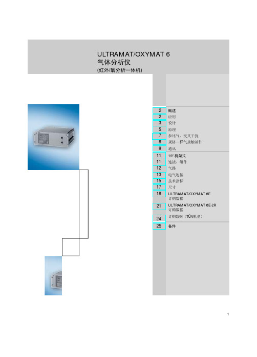
ULTRAMAT OXYMAT 6型气体分析仪
原理
1 红外线源,可调
8 参比气室
2 光学过滤器
9 样气出口
3 光束分离器(气体过滤器) 10 检测器,左
4 旋转电流驱动器
11 检测器,右
5 斩光器
12 微流量传感器
6 样气入口
13 光耦合器
7 样气室
14 滑动触头,可调
图2 ULTRAMAT/OXYMAT 6,ULTRAMAT 通道原理图
5
ULTRAMAT/OXYMAT 6 概述
该补偿回路以减小因样气和参比气密度相差太大 时产生的振动偏差
• 内部压力传感器校正样气压力在 500~2000hPa 绝压范围内的波动
• 使用硬管气路时,可连接外部压力传感器来校正 工艺气在高达 3000hPa 绝压范围内的压力波动
• 参比气接入压力为 3000-4000 hPa 时进行参比气 压力监测(可选)
当前量程显示
OXYMAT 通道状态行 (显示分析仪状态, 可编程)
退出键 显示帮助信息
消除键
确认键
图1 ULTRAMAT/OXYMAT 6,控制面板及其图形显示
返回到测量模式
4
ULTRAMAT/OXYMAT 6 概述
ULTRAMAT 通道测量原理
ULTRAMAT/OXYMAT 6 气体分析仪的 ULTRAMAT 通道采用交替红外双光束原理并使用双层检测气室和 光耦合器来测量气体。
测量原理基于分子特定的红外光吸收波段。对于不同 气体,虽然其吸收波长各不相同,但也可能有部分重 叠。这导致产生交叉干扰。ULTRAMAT 6 通道采用 以下措施来最大限度的降低这种交叉干扰:
• 滤波气室(分光器) • 带有光耦合器的双层检测气室 • 必要时可使用滤光片
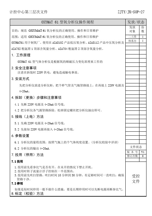
ZJTYJK-SOP-27 OXYMAT 61型氧分析仪操作规程
5.1先确220V电源及4-20mA信号线。
5.2先接如220V电源再接入4-20mA信号线。
6.参数设置
6.1分析仪的量程范围,按照气瓶上的个气体纯度设置。(分析仪校验中详讲)
6.2分析仪的输出4-20mA.
7.投用(停用)方法
7.1投用
1.投用前先看参比气是否有开,在未开的情况下禁止开机。
量程
1级密码
参数
1级密码
配置
2级密码
工厂将1级密码和2级密码分别设置为值“111”和“222”
8.零点,再打开零点气压力控制在
0.2MPA,等数值稳定后按确定标定。
8.2量程标定
先确保参比气是开着的,把分析仪前四通阀指向量程,再打开零点气压力控制在
0.2MPA,等数值稳定后按确定标定。
10.4停用时先看是否是长时间停表,如果不是可不做任何措施。
时的中断,参比气也应该继续通入。如果参比气路没有泄漏,那么额外消耗量所引
起的后果就无关紧要。
10.3无论是在投用时还是标定时首先参比气必须是开着的,在未开参比气的情况
下禁止投用,参比气压力设置在0.2MPA~0.4MPA通常设0.3MPA,如果压力过高容
易打坏分析仪内探头,探头类似玻璃片比较容易打坏U6,O6,C6都有同样弱点。
OXYMAT 61型气体分析仪是根据氧的顺磁压力变化原理来工作的
2.安全注意事项
注意在拆装时220V供电,避免造成触电事故。
3.安装方式
先把分析仪放进分析仪柜,把个样气管及气瓶管路接上,在再接上220V电源及
4-20mA。
4.拆卸(更换)步骤和注意事项
4.1先断220V电源及4-20mA信号线。
4.2把分析仪各气源管路拆除,松掉固定螺丝把分析仪抽出即可。
西门子O2分析仪PPT课件
-
3
2、样气气路
参比气经过两个参比气通道 (3) 进 入样气室 (6)。其中一路参比气在磁场 区域 (7) 和样气相遇。因这两个通道是 连通的,所以与氧浓度成正比的压力差 使得两路参比气形成气流。微流量传感 器 (4) 感知该气流并将其转变为电信号。 微流量传感器中有两个被加热到大约 120 ?C 的镍格栅,这两个镍格栅和两 个补充电阻形成惠斯通电桥。变化的气 流导致镍格栅的电阻发生变化。这使电 桥产生偏移。该偏移值大小决定于样气 中 的氧气浓度。 微流量传感器位于参比气路中,不直接 接触样气,所以样气的热导率、比热和 样气的内部摩擦对测量结果都不产生任 何影响,同时,这也避免了样气对微流 量传感器的腐蚀,使得微流量传感器 的抗腐性能大大提高。 *通过改变磁场强度 (8),使得微流量传 感器上的背景气流不被检测。仪器摆放 的方向因而对测量也无影响。
• 中,放弃这些修改则按NO。 • 如果需要进行频繁的输入,则会引入一个“超级用户”,它允许从测量显示立即转换
到所需要的功能显示,因此这就可能跳过菜单级而直接进入到所需的功能。“超级用 户”输入只可以从测量模式开始并包括以下几个输入步骤:
• ·在测量显示中,使用数字键输入所需的功能号。
• ·按下所需组分旁的软键。
-
13
5、圆点处) • →CALIBRATION(校准) • →一级参数(密码111) • →SPAN CALIBRATION(量程校准) • →量程含量(修改、选择) • →量程标定(YES/NO) • →稳定后按“确认键”。
-
14
6、维护注意事项
• 1、新氧表投运前需要预热5-6小时,并通入参比气( 99.999%的纯N2),预热后引入样气。
-
4
OXYMAT61型氧气分析仪
OXYMAT61型氧气分析仪
OXYMAT61采用了先进的光学传感器技术,具有非常高的精度和稳定性。
该传感器使用两个特殊的氧气电极,通过电化学反应来测量样品中的氧气浓度。
这种技术可以确保准确的测量结果,并在长时间使用过程中保持稳定性。
该分析仪还具有高度灵活的功能,可以通过现场可编程的操作面板进行配置。
用户可以自定义测量范围、测量单位、报警设置等。
此外,分析仪还具有数据记录功能,可以存储最多1000个测量数据和报警事件。
此外,OXYMAT61还具有多种数据通信接口,可以与计算机或其他设备进行连接。
这使得数据的传输和分析变得非常方便。
分析仪还配备了标准的模拟输出和数字接口,以便与外部设备集成。
总的来说,OXYMAT61是一种功能强大、精确可靠的氧气分析仪。
它适用于各种领域的氧气测量需求,并提供了灵活的配置和数据通信功能。
无论是在医疗、工业还是环保领域,OXYMAT61都是一个理想的选择。
ULTRAMAT 6型红外气体分析仪
ULTRAMAT 6
概述
气体分析仪
■概述
ULTRAMAT 6 型 单通 道或 双通 道红 外气 体分 析仪 ,采 用交 变 NDIR 双 光 束测 量原 理 ,具 有高 度 的选 择 性, 测量 那些 红 外吸 收 波段 在 2~9 µ m 范围 内的 气体 , 例如 : CO,CO 2,NO,S O 2 ,NH3 ,H 2 O , CH 4 以 及其 它碳 氢化 合物 。 单 通道 分析 仪最 多可 测量 2 个 气体 组分 ,而 双通 道分 析仪 则最 多 可 同时 测量 4 个 气体 组分 。
输 入和 输出
• 每个 测量 组分 一个 模拟 输出
ULTRAMATHale Waihona Puke 6 , 薄膜 键盘 和图 形显 示器
3
ULTRAMAT 6
概述
气体分析仪
规 格- 与样 气接 触部 件, 标准 型
气路 软管 衬管 软管 样气 室: • 主体 • 内衬 • 柱 形气 室 • 窗口 硬管 衬管 连接 管 样气 室: • 主体 • 内衬 • 窗口 硬管 衬管 连接 管 样气 室: • 主体 • 内衬 • 窗口 铝 钛 或钽 (钽 :只 用于 测量 室长 度 20 mm ~18 0m m) CaF 2, 粘合 剂: E353, O 型密 封圈 :FK M ( 如 Viton) 或 FFKM (Kalrez) 铝 钽 (只 用于 测量 室长 度 20 mm ~18 0m m) CaF 2, 粘合 剂: E353, O 型密 封圈 :FK M ( 如 Viton) 或 FFKM (Kalrez) SS , 牌号 1.4 571 SS , 牌号 1.4 571 O 型密 封圈 :FK M ( 如 Viton) 或 FFKM (Kalrez) 铝 铝 SS ,牌 号 1. 457 1 O 型 密封 圈: FKM ( 如 V iton ) 或 FFK M (K alrez) CaF 2 , 粘合 剂:E35 3, O 型 密封 圈: FKM ( 如 V iton ) 或 FFK M (K alrez) 钛 钛 O 型密 封圈 :FK M ( 如 Viton) 或 FFKM (Kalrez) 19" 架 装型 SS ,牌 号 1. 457 1 FKM ( 如 V iton ) 现场 安装 型 防爆 型现 场安 装型
ULTRAMAT6红外气体分析仪-西门子中国
产品目录 • 2014
Answers for industry.
ULTRAMAT 6 红外气体分析仪
2 概述 2 介绍 2 特性 2 应用 2 设计 4 功能 5 19" 架装型 5 技术规格 6 选型和订货数据 9 外形尺寸图 9 电气连接图 12 现场安装型 12 技术规格 13 选型和订货数据 15 外形尺寸图 16 电气连接图
特殊应用
除上述标准应用之外,还可根据客户要求提供需考虑气路材质和 样品室材质的特殊应用。
流动参比室类型
• 流经参比室的流量应该与样品气的流量相匹配。
• 当参比室的入口压力在 3000hpa 与 5000hpa 绝压下,须减少参 比气,限流器会自动调整流量在 8ml/min。
ULTRAMAT 6, 19" 架装型和现场安装型
单通道分析仪最多可测量 2 个气体组分,而双通道分析仪则最多 可同时测量 4 个气体组分。
标准应用 • 燃烧装置中锅炉控制用测量 • 烟气排放的污染物测量 • 焚化装置排放监测 • 汽车工业 (发动机性能测试系统) • 报警设备 • 化工厂中的工艺气体浓度测量 • 高纯气体的品质检验 • 环境保护 • 工作场所 MAC 值监测 • 质量监测 • 防爆机型用于危险区域分析易燃和非易燃气体或蒸汽
ULTRAMAT 6, 薄膜键盘和图形显示器
3
气体分析仪
ULTRAMAT 6
概述
■ 功能
测量原理
ULTRAMAT 6气体分析仪采用交变红外双光束原理,并使用双层检 测器和光耦合器来测量气体。
测量原理基于气体分子具有特定的红外光吸收波段。对于不同气 体,其吸收波长各不相同,但可能有部分重叠,这导致产生交叉 干扰,ULTRAMAT 6 采用以下措施来最大限度降低这种交叉干扰: • 充满的滤波气室 (分光器) • 带有光耦合器的双层检测器 • 必要时可使用特殊滤光片 下图出示了分析仪的测量原理。一个红外光源 (1) 被加热到约 700 °C。光源发出的光经过分光器 (3)被分成两路相等的光束 (测量光束和参比光束)。红外光源可左右移动以平衡光路系统。
- 1、下载文档前请自行甄别文档内容的完整性,平台不提供额外的编辑、内容补充、找答案等附加服务。
- 2、"仅部分预览"的文档,不可在线预览部分如存在完整性等问题,可反馈申请退款(可完整预览的文档不适用该条件!)。
- 3、如文档侵犯您的权益,请联系客服反馈,我们会尽快为您处理(人工客服工作时间:9:00-18:30)。
O2
9
1. 2. 3. 4. 5. 6. 7. 8. 9. 10.
10
֖Բഘ੨ ၌ୁጎዃ ֖Բഘཚڢ ᆩᇀ֪ଉୁྲڦଉ ߌدഗ ᄣഘ੨ ᄣഘ ຩىၳᆌ Վࣅഽ༹ىۉڦ܈ ᄣഘࢅ֖Բഘ੨ ցဣཥዐڦၭୁଉ ߌدഗDŽഘୁDž
OXYMAT 6 型氧分析仪的工作原理图
5 6
O2 O2 O2 O2 O2
7
8
主要特点
• • • • • • • • • • • • • • • • • • • • 四个可自由编程量程,带有零点偏移,所有量程都是线性的 所有量程带零点补偿 量程识别 电气隔离信号输出,输出可选 0/2/4 ~20 mA ( 也可反置 ) 自动量程或手动量程切换;也可远程切换量程 仪器标定过程中可存储测量值 时间常数在较宽范围内可选 ( 静态 / 动态噪声抑制 ) ;即,分析 仪的响应时间可与相应应用相匹配 响应时间短 长时间漂移小 多点测量最多 6 个测量点 ( 可编程 ) 测量点识别 用内部压力传感器来校正样气压力波动:波动范围 50~200 kPa 绝压 可连接外部压力传感器来校正样气压力在 300 kPa ( 绝压 ) 内的 波动 (可选) 样气监测和 ( 或 ) 参比气监测 ( 可选 ) 监控样气流量 ( 对于 Viton 管型为可选 ) 参比气接入压力为 300-500 kPa 时进行参比气监测 ( 可选 ) 量程自动标定参数化 基于 NAMUR 推荐的操作模式 两级独立密码设置可避免无意或其它无相关权限人员的输入 使用带操作员提示功能的数字膜状键盘可让操作简单化
氧气分析仪
产品目录 • 2014
OXYMAT 6
OXYMAT 6 氧气分析仪
2 2 2 2 2 4 5 5 5 6 7 9 9 10 10 11
概述 介绍 特性 应用 设计 功能 19" 架装型 技术规格 选型和订货数据 外形尺寸图 电气连接图 现场安装型 技术规格 选型和订货数据 外形尺寸图 电气连接图
OXYMAT 6, 19" 架装型和现场安装型
■ 特性
• 顺磁压力最变化原理 - 测量量程最小 ( 最小量程 0-0.5% 或最大量程 99.5-100% O2) - 完全线性化 • 检测单元不接触样品气 - 可用于测量腐蚀性气体 - 使用寿命长 • 通过选择适合的参比气体 ( 空气或氧 ) 可以使量程不从零开始, 如 98-100% O2 测量, 用于高纯气监测 / 空分 • 开放的接口结构 (RS 485, RS 232, PROFIBUS) • 用于维护和服务的 SIPROM GA 网络 ( 可选 ) • 电气和物理特性:气密隔离,可以吹扫,防护等级 IP65 - 在恶劣的环境中仍具有很长的使用寿命 • 加热型 ( 可选 ),可在低温下有冷凝气体的情况下使用 • 防爆等级 EEx(p),用于 1 区和 2 区 • SIL2 认证 (安全完整性等级)
• 客户可按自己的要求选择: - 工厂验收 - 标签 - 漂移记录 - O2 清洗 - Kalrez 垫圈 • 分析部分带流动型补偿回路:在该补偿回路中通过一种气体可 减小因样气和参比气密度相差太大时产生的振动偏差 • 分析仪电气连接部分容易拆卸,更换部件更容易 • 耐高腐蚀性气体的样气室
1224来自3 3OXYMAT 6
概述
ý¯Ã²÷Œˆ“«
气体分析仪
■ 介绍
OXYMAT 6 型氧气分析仪采用测量顺磁压力变化的方法来测量气 体中的氧气浓度。
■ 设计
19" 架装型 ,可安装在: • 4 HU (标准高度) - 铰链连接机架 - 机柜中,可带或不带滑轨 • 如需维修,前面板容易拆卸 ( 例如:连接便携式电脑 ) • 内部气路 :FKM (Viton) 软管,钛管或不锈钢管 • 样品气进口与出口气路连接及参比气路连接:柱形气室,管径为 6 mm 或 1/4" • 前面板上安装样气流量计 (可选) • 有用于样品气流量监控的压力开关 (可选)
现场安装型
• • • • • • 2 扇门式机箱,使气体分析部分和电子部分同时做到气密隔离 机箱的气路部分和电器部分可分别进行吹扫 分析部分及其管线可最高加热到 130 °C ( 可选 ) 气路和管线接头材质为不锈钢、钽或哈氏合金 吹扫气连接:管径为 10 mm 或 3/8" 样品气进口与出口气路连接及参比气路连接 :管径为 6mm 或 1/4" 的连接
输入和输出
• 1 个模拟量输出 (从 0,2,4 到 20mA 输出) • 2 个可编程模拟量输入 ( 例如:用于校正交叉干扰或外部压力传 感器信号 ) • 6 个可任意配置的二进制输入 ( 例如:用于量程切换、处理来自 样气处理系统的外部信号 ) • 6 个可任意配置的继电器输出 ( 例如 :用于故障报警、维护请求、 维护开关任意、超限报警、外部电磁阀 ) • 可另扩展 8 个附加的二进制输入和 8 个继电器输出 ( 例如:可 用来进行多达四种标气的自动标定 )
通讯
• RS 485 为标准配置
选项
• • • • • • 用于汽车工业带扩展功能的 AK 接口 RS 485/RS 232 转接器 RS 485/ 以太网转接器 RS 485/USB 转换器 通过 PROFIBUS DP/PA 接口接入网络 SIPROM GA 软件
特殊应用
除上述标准应用之外,还可根据客户要求提供需考虑气路材质和 样品室材质的特殊应用。
4
气体分析仪
OXYMAT 6
机架式 19? 架装型 19''
■ 技术规格
概述 量程 4 个,可实现内部 / 外部切换,可 进行自动量程切换 最小量程 ( 参照 100 kPa 的绝对样气 0.5 Vol%, 2 Vol% 或 5 Vol% O2 压力,0.5 l/min 样气流量和 25 °C 环 境温度 ) 最大量程 量程,带零点校正 100 Vol% O2 ( 压力达到 200 kPa: 25 Vol % O2) 如果选用合适的标准,在 0-100 Vol% 间任何一点均可设为零点 ( 参见表 1) 前面板垂直安装 CE 认证 EN 50081-1, EN 50082-2 IP 20,按照 EN 60529 标准 约 13 kg 100 - 120 V AC ( 额定范围为 90 V 至 132 V), 48 至 63 Hz 或 200 - 240 V AC ( 额定范围为 180 V 至 264 V), 48 至 63 Hz 约 35 VA 符合 NAMUR NE21 (08/98), EN 61326, EN 50270 标准的要求 ( 带气体报警单元 ) 根据 EN 61010-1,过压级别 III 100 ... 120 V: 1.0T/250 200 ... 240 V:0.63T/250
操作位置 标准 设计,机箱 防护等级 重量 电气特性 电源
影响变量 ( 参照 1013hPa 的绝对样气压力, 0.5 l/min 样气流量和 25 °C 环境温度 ) 环境温度 样气压力 ( 以空气 (10 kPa) 作参比气 时,只有当样气直接排放到室外空气 中时,才可实现大气压力波动的平衡 ) 载气 样气流量 < 铭牌上规定的最小量程的 0.5%/ 10 K,量程 0.5%:1%/10 K 无压力补偿:< 当前测量量程的 2% / 压力变化 1% 有 压 力 补 偿:< 当 前 测 量 量 程 的 0.2% / 压力变化 1% 零点偏移相当于载气的顺磁或逆磁 偏移 < 最小量程 ( 参照铭牌 ) 的 1%/ 在 允许的流量范围内流量变化 0.1 l/min < 输出信号量程的 0.1% / 额定电压 10% 0/2/4-20 mA,隔 离 输 出,最 大 负 载:750 6 个,输出可通过转换触点自由选 择,如用于量程识别,负载容量; 24 V AC/DC/ 1 A,隔离输出 2 个输入,0/2/4-20 mA,用于外部 传感器和残余气体的干扰校正 ( 校正交叉干扰 ) 6 个输入, 24 V,隔离输出,可自 由选择,如用于量程切换 RS 485 自标定功能,带有 8 个二进制输入 和 8 个继电器输出;也带有 PROFIBUS PA 或 PROFIBUS DP 操作温度:+5 ~ +45 °C,仓储和运 输温度:-30 ~ +70 °C 仓储和运输时:年平均 < 90% 相对 湿度 ( 不可低于气体露点 )
显示屏和控制面板
• 大屏幕 LCD 可同时显示: - 测量值 ( 数字量和模拟量显示 ) - 状态栏 - 量程 • 可通过菜单操作调节液晶显示器的对比度 • 持久的 LED 背光显示 • 可擦洗的带有 5 个软键的膜状键盘 • 通过菜单操作进行配置、功能测试、标定 • 纯文本格式显示用户帮助 • 可图形显示浓度趋势图;时间间隔可设定 • 操作软件采用 2 种语言:德语 / 英语,英语 / 西班牙语,法语 / 英语,西班牙语 / 英语,意大利语 / 英语
■ 应用
• • • • • • • • • • • 控制焚烧装置中的锅炉 与安全相关的领域 作为排放监测中的参考变量 ( 根据德国 TA-Luft 气体排放标准 ) 汽车工业 ( 发动机性能检测系统 ) 报警装置 化工厂 高纯气体的品质检验 环境保护 质量监测 可如同经过认证的气体报警设备 (DMT) 那样监视惰性气体 防爆机型用于危险区域分析易燃和非易燃气体或蒸汽
压力校正范围 压力传感器 • 内部 • 外部 50 - 200 kPa 绝压 50 - 300 kPa 绝压
测量响应 ( 参照 1013hPa 的绝对样气压力, 0.5 l/min 样气流量和 25 °C 环境温度 ) 输出信号波动 零点漂移 量程漂移 重复精度 最小检测限 线性误差 < 铭牌上最小量程 0.75%,时间常 数为 1 s ( 此时为 0.25%, 2) < 铭牌上最小量程的 0.5%/ 月 < 当前测量量程的 0.5%/ 月 < 当前测量量程的 1% 当前测量量程的 1%,最小可达 50ppm < 当前测量量程的 0.1%