旋转拼接融合处理器说明书
VS3 多画面拼接处理器 用户手册说明书

VS3多画面拼接处理器V1.0.3 NS160000617用户手册安全声明为避免可能的危险,请按规定使用此设备。
如出现损坏,非专业人士请勿擅自打开维修,请及时与本公司售后联系。
高压危险:本产品的工作电压为接地:本产品通过电源的地线与大地相连,请确保接地导体的良好接地。
电磁干扰:设备应远离磁铁、马达及变压器。
防潮:请将设备置于干燥、干净的环境中。
如有液体浸入,请立即拔掉电源插头。
远离易燃易爆危险物品。
禁止液体、金属碎片浸入机器内部,以免引起安全事故。
目录1 功能简介 (1)1.1前面板示意图 (1)1.2后面板示意图 (1)1.3电气参数 (2)2 信号连接 (4)3 菜单操作 (5)3.1主界面 (5)3.2主菜单 (5)3.3屏体设置 (6)3.4窗口布局 (6)3.5场景切换 (7)3.6输入设置 (7)3.7画质调整 (7)3.8画面控制 (7)3.9高级设置 (8)3.10通讯设置 (8)4 配套控制软件 (9)5 常见问题 (10)1 功能简介1.1 前面板示意图输入源切换说明点按输入源选择快捷键时仅切换某个窗口的信号源,该窗口可以进行指定。
按5-WIN键后调出如下窗口指定菜单:高优先级切源:按照窗口布局中设置的优先级切源,哪个窗口的优先级最高(在最上层)即对该窗口的输入源切换;窗口1/2/3切源:指定对某一窗口进行输入源切换。
说明:●输入源被分为A、B、C、D四组,两路输出必须是不同组的信号,也即只有不同组的两个信号源可以被同时输出。
●MODE补充说明:用户可以使用配套控制软件对各个场景进行重命名。
1.2 后面板示意图1.3 电气参数2 信号连接3 菜单操作3.1 主界面开机后,显示屏显示主界面如下:●A:信号源的输入情况:蓝色表示该信号源正在使用中;黄色表示该信号源有输入但当前未被使用;灰色表示该信号源未连接。
●B:当前开窗情况,蓝色表示开窗有信号源输入。
●C:输出接口情况和输出分辨率。
大视电子 MM5000 飓风系列 超高清拼接处理系统 说明书

MM5000飓风(Tornado)系列超高清拼接处理系统说明书Multiple views, multiple lives上海大视电子科技有限公司兼容灵活MM5000飓风(Tornado)系列超高清拼接处理器面板图(1.5U,2U,3U,8U,12U,18U,26U)MM5000飓风(Tornado)系列超高清多屏拼接处理器是采用纯硬件线速处理架构的高性能视频图像处理系统,适用于教育科研、政府公告、信息出版、行政管理、军事指挥、展览展示、安防监控、商业销售等行业。
它集多路高清、超高清视频信号采集、实时高分辨率数字图像处理、复杂图像变换处理等高端图像处理功能于一身,具有强大的信号处理能力。
运行流畅无损画面l架构设计l➢纯硬件FPGA架构无内嵌操作系统,内部自建高性能处理算法,图像处理性能优异。
全新的大视电子第四代硬件处理架构,Flexview M8核心处理算法,具备图像信号全硬件点对点能力,4K/8K多路超高分信号处理支持,实时无损处理,独有全帧保持技术保证无丢帧现象,超并行处理机制和全同步处理架构,保证所有输出严格全同步,所有画面无撕裂。
l 输入卡l➢任意组合多种输入卡DVI-M、HDMI、Displayport、VGA、DVI、DualLink DVI、SDI、CVBS、HDBaseT、YPbPr/YCbCr、IP、光纤等。
➢超高清输入卡支持最高8Kx4K超高分辨率输入,支持多接口分辨率组合➢输入卡任意混插机制实现输入扩展的极大灵活性l 输出卡l➢支持800x600-2048x1200@60Hz分辨率,同时支持主动立体输出 1024x768-1280x800@120Hz➢超高分输出卡支持1920x1080@120Hz 及4K@60Hz,4K@30Hz分辨率➢输出支持冗余备份输出,防止意外静电损坏。
➢输入输出支持自定义任意拼接,可选任意角度旋转和任意间距创意拼接,支持0-360度旋转,1度为单位(该功能为选配)l 系统连接及控制l➢支持网络和RS232串口调试,支持系统定时,同时提供额外RS232串口,可以控制矩阵/投影机等。
融合调试简易操作说明书
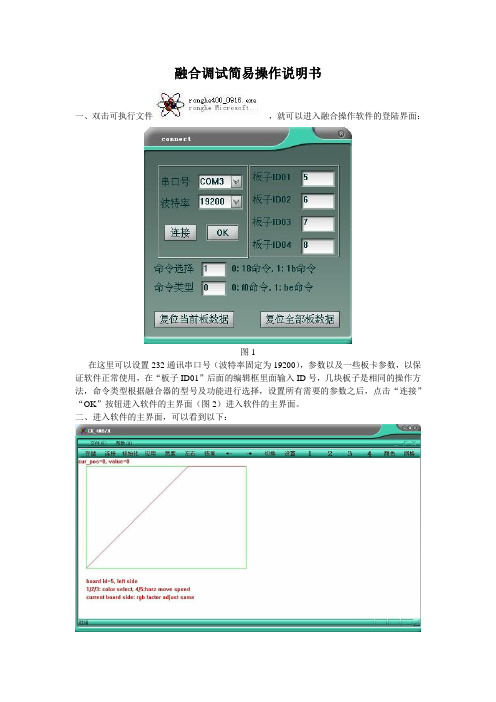
注:
以上是新版融合调试软件的简易说明书,请大家多多指教,如果在测试和使用的过程中,有好的修改建议或者发现有BUG以及操作不便之处,能及时反馈于我,我继续完善软件。
图10板卡ID和融合宽度
9、选择板卡序号“ ”“ ”,然后点击“ ”是可以实现在“宽度”里面设置的宽度信息来抓取像素,然后选择不同的板卡然后分别点击“ ”进行像素抓取,点击之后看到如下:
图11
10、选择“ ”“ ”,可以任意选择调节所需要的板卡进行调整,方便操作。
11、选择“ ”可以对“亮度”“对比度”等一些颜色来调整。点击可以看到如下:
4、选择“ ”这里是对消隐参数的设置,板卡的“融合宽度”“右融合开始”“下融合开始”等一些数据设置。设置完毕之后点击“OK”即可。
图7
5、选择“ ”可以对不同板卡进行“上、下、左、右”方向的选择。
6、选择“ ”可以恢复前面设置的曲线参数,如果上一次,选择的参数调节之后,出现了自己不愿意想得到的效果,现在可以选择“恢复”曲线和消隐区域,更新了发送模式,实现点击即可恢复,达到了不用等待的效果。
7、选择“ ”可以对已经设置宽度和调节参数的曲线让左右两个方向上移动,实现消隐区的移动,可以达到的更好的调节作用。
8、选择“ ”可以对以下3种状态切换,如下图:
(1)、融合调整状态。
图8融合调整
(2)、Gamma调整状态,调节功能暂时没有开放。
图9Gamma调整(未开放)
(3)、板卡信息显示状态。在这个状态先,选择“ ”“ ”可以查看不同的板卡此时所对应的具体的ID和融合宽度。
选择“载入数据”就可以载入上一次所保存的参数,实现了快速调去数据参数的功能,便于解决在使用过程中的不当操作。
图5
注:建议在调整好融合之后,保存已经调整好的参数,以便下次载入。
多画面拼接 处理器ZX-KS920Plus产品说明书本

多画面拼接处理器(XB)使用说明书声明感谢您使用本公司的产品。
本手册版权属本公司所有,在未征得本公司的书面许可的情况下,严禁以任何形式复制、传递、分发和存储本文档的任何内容。
本公司保留在不预先通知的情况下对本文档中所描述的任何产品功能进行修改和改进的权利。
本产品可能附带有相关的控制软件,该软件仅供您使用,软件的所有权归本公司所有。
您可以进行拷贝,但仅限于个人使用。
若您将此软件用于其它用途,特别是商业用途,请与本公司取得联系。
本公司保留追究侵权行为法律责任的权利。
请您在使用前仔细阅读本手册,操作不当,有可能对产品造成损害;本产品为带电工作产品,请注意用电安全。
若不按照本手册的说明,采取不得当的操作,因而造成的财产损失和人身伤害,本公司不承担责任。
此条如与当地法律法规相抵触之处,以当地法律法规为准。
如果您使用了本产品,意味着您同意以上声明,若您不同意以上声明,则请您与销售方联系,办理相应的退货手续。
认证说明“CE”认证EN 55022:2010EN 55024:2010EN 61000-3-3:2013EN 61000-3-3:2014EN 0950-1:2006+A11:2009+A1:2010+A12:2011+A2:2013“FCC”认证FCC Part 15ANSI C63.4:2014“ROHS”认证EPA 3050B:1996,EN1122:2001EPA 3052:1996,EPA 3060AEPA 7196,EPA 3540C,EPA 8270C版本信息版本: v1.0发布日期: 2016年9月安全注意事项为了您的安全,请仔细阅读本节。
目录1.产品简介 (1)2.硬件介绍 (2)2.1前面板 (2)2.2后面板 (3)3.设备调试 (4)3.1设备连线 (4)3.2调试步骤 (5)3.3案例讲解 (8)3.4功能按键: (14)3.5高级菜单 (17)4.技术参数 (18)5.常见问题解答 (19)附:显卡复制模式与扩展模式的设置 (21)1、AMD显卡 (21)2、NVIDIA显卡 (22)1.产品简介多画面拼接处理器是由本公司研发生产的面向LED大屏幕显示、演出与租赁、会议室、演播室等市场的高端视频处理设备。
M8-M9融合器使用手册(试用版)
M8/M9拼接融合器使用手册目录1. 前言 (2)1.1 产品功能与用途 (2)1.2 产品特点 (2)1.3 标准包装内容 (2)2. 外观名称及功能 (3)2.1 前面板 (3)2.2 后面板 (3)2.3 遥控器 (3)3. M8 /M9使用操作前相关设定 (4)4. OSD选单及遥控器基本操作 (4)5. 几何调整测试图案 (6)6. 画质调整(Picture Adustment) (7)6.1 亮度调整 (7)6.2 对比度调整 (7)6.3 色调调整 (7)6.4 饱和度调整 (7)6.5 锐利度调整 (7)7. 图像位置调整(PC Image Setup)..................................... .. (8)7.1 自动设定 (8)7.2 手动设定 (8)7.3 水平位置 (8)7.4 垂直位置 (8)8. 电视墙(影像分割及位置设定程序) (9)9. 3D设定............................................................... (11)9.1 系统设置............................................................... .. (11)9.2 M9的3D投影设定............................................................... (12)9.3 3D选单及操作............................................................... .. (13)10. 几何调整(Anyplace) (14)10.1 梯形校正 (14)10.2 旋转校正 (15)10.3 边角校正 (16)10.4 边缘融合校正 (18)11.选项(Options) (23)11.1 信息 (23)11.2 语言 (23)11.3 工厂设置 (23)11.4 OSD响应时间 (23)11.5 系统设置 (24)12. RS-232 控制 (25)13. Ethernet 网络控制系統 (25)1. 前言1.1 产品功能及用途M8 / M9为多功能的专业影像处理机,操作简单,不需电脑,可在很短的时间內完成复杂的多台投影机或影像的大型显示系统,其主要用途为:a. 多台投影机的拼接融合(含弧型荧幕拼接融合)b. 多显示功能的电视墙(在电视墙中,在不同的显示器內仍可设定不同的显示內容)c. 曲面投影d. 投影机3D立体投影显示(采用健康舒适的偏光眼镜方式)e. 各种影像格式的转换1.2 产品特点a. 专业耐久的设计b. 超高解析度,输入解析度可达:2560x1600c. 设计有DisplayPort输入界面,可支援AMD Eyefinity技术,可利用一台电脑及一张低成本的显示卡,同时达到显示6个1080P影像。
融合器调试使用说明书
图像处理器用户手册目录安全操作指南 (3)包装配件说明 (3)一、概述与应用场合 (4)二、性能规格参数 (5)三、特点 (6)四、系统拓扑图 (7)五、后面板接口介绍与接入说明 (8)软件部分使用说明 (9)1、软件的登录及详细设置 (9)2、软件界面介绍 (10)3、输出板卡分辨率设置 (12)4、输出板卡颜色单独调节 (13)5、场景设置及保存操作说明 (14)6、串口控制协议 (17)七、常见问题及解决方法 (18)为确保设备可靠使用及人员的安全,请在安装、使用和维护时遵守以下事项:①在设备安装时应确保电源线中的地线接地良好请勿使用两芯插头, 确保设备的输入电源为 220V50Hz 的交流电。
②机器内部有交流220V高压器件,请勿擅自打开机壳,以免发生危险。
③不要将系统设备置于过冷或过热的地方。
④设备电源在工作时会发热,因此要保持工作环境的良好通风,以免温度过高而损坏机器。
⑤阴雨潮湿天气或长时间不使用,应关闭电源总闸。
⑥在下列操作之前一定要将设备的交流电源线从交流供电电源拔下:A 取下或重装设备的任何部件。
B 断开或重接设备的任何电器插头或其它连接。
⑦非专业人士未经许可请不要试图拆开设备机箱不要私自维修以免发生意外事故或加重设备的损坏程度。
⑧不要将任何化学品或液体洒在设备上或其附近。
包装说明1、融合器主机一台2、机架安装耳朵一对,配套3X8沉头镙丝8颗3、DVI转VGA转换头根据融合器的DVI-I接口个数4、RS-232通讯连接线1条5、电源线1条6、(应用软件+说明书)光盘1个7、系统用户手册1本8、合格证、保修卡各1一、概述及应用场合画面融合器融合器又叫边缘融合器或无缝拼接器当二台或多台投影机组合投射一幅画面时,会有一部分影像灯泡重叠,边缘融合的最主要功能就是把二台或多台投影机重叠部分的图像灯光亮度逐渐调低,使整幅画面亮度一致,从视觉上看去像一台投影机投出来的效果。
边缘融合的应用来源于模拟仿真/立体影院系统。
SL450A旋转接头操作手册说明书

SL450A ROTARY SWIVEL OPERATION MANUALSL450A-SMGoldenman Petroleum Equipment Co., Ltd Add:7/F, Wanda International Mansion, 67 Fuqian Street , Dongying China Tel:+0086-546-8058779 E-mail:********************CONTENTSI.Technical specifications (2)II.Structure instructions (2)III.Installation (3)IV.Operation (4)V.Lubrication (4)VI. Replacement of Packing Device (4)VII.Maintenance (5)VIII.Inspection and Debuggingent (6)IX.Packing and Shipping (7)X.Recommended Spares List (8)Please read the following operation manual before installing and operating the Swivel. It is necessary to confirm its maximum static loading for operation.The design and operation temperature for the product is -20°C(-4°F). It is necessary to inform lowest working temp when order the product.Regularly conduct NDT on main bearing parts (housing, central pipe, bail and bail pin).I. Technical Specification1. Max. Static Load 4500kN2. Max. RPM 300r/min3. Max. Working Pressure 35MPa4. Central Pipe ID. Ø75mm5. Sub connection 65/8 REG L.H.6. Gooseneck connection 4 LP API Std5B7. Air motor model FMS208. Air pressure 0.7-0.9MPa9. Air consumption 20m3/min10. Spinning speed 92rpm11. Brake torque 2940N.m12. Weight 3310kgII. Structure InstructionsSee Fig.1, SL450A rotary swivel consists of rotary part, fixed part, support part, sealing part and spinning part. Rotary part is composed of central pipe(14) and sub(24). Fixed part includes housing(15), upper cover(2), lower cover(18), gooseneck(10), bail(25) and bail pin (7). Support part consists of main bearing (16), guide bearing (12), and lower guide bearing (20). Seal part includes packing device and upper and lower seal rings. Spinning part covers air motor, air control clutch.Central pipe supports whole weight of drill string and inner mud pressure. Its connection thread with sub and the connection thread of sub and kelly meet API Spec 7-1 and 7-2 requirements.Central pipe is a kind of hollow part. Its upper end connects with packing device (Fig.1),its lower end connects with sub, and its middle part sits on the main bearing with two guide bearings centralize it, among which the upper guide bearing also has the function to avoid central pipe going up. Rubber umbrella (4) on top of the central pipe prevents mud from entering into swivel body.Bail which connects housing via two bail pins is to hang the swivel on the hook. Housing is a support part and is a oil pool for lubricating and cooling main bearings and guide bearings. On its two ends are top cover and bottom cover, on the external size is fitted with buffer (9) to avoid elevator ring impacting housing. Under the top cover is equipped with guide bearing and two oil seals(8). Those two seal rings should be installed in opposite directions, which will prevent oil leaking and mud entering. In top cover there is a thread hole fitted with an oil scale with relief valve function. When air pressure inside housing is higher than outside, the valve will auto open and discharge air. The gooseneck with a thread hole in the top is fixed on the top cover flange. The thread hole is designed for well logging. In drilling process, the hole is sealed with a plug (1) to avoid mud spilling. One end of gooseneck is connected with packing device, the other end is to connect with rotary hose via inner joint (API Std. 5B). Inside the lower cove is fitted with lower guide bearing with three oil seals (21).The packing device connects with the central pipe and the gooseneck pipe, which forms passage for drilling fluid. The packing device is an important part for sealing high pressure mud. It features self-sealing and quick disassembling structure. When wash pipe and packings are worn and needed to be replaced, only need to screw off the upper and lower nuts, then you can take out the whole device from one side, no need to disassemble gooseneck or rotary swivel. Simple, convenient, and can replace any time.Power reducer assembly (11) is secured with bolts and nuts on the upper plane of lower flange of top cover (2). It is an important part for spinning. Spinning is realized by control air valve. Look down at central pipe, clockwise rotation is called forward rotation and anti-clockwise rotation is reverse rotation.III. InstallationRefer to Fig.2 for installation of the spinner. Main control valve (8, left) controls the swivel’s spinning working and its stop. Reverse control valve is to invert the swivel’s rotation. Care should be taken to shut off the main air-in valve (20) when need to change rotation direction of the spinner.IV. OperationLoad test and dynamic pressure test for a new swivel have been conducted before leaving the manufacturing plant, and there is no oil in the swivel housing. So before use, must do the following.1. Unscrew and remove the oil scale, fill with lubricate L-CKC150 (to max. scale), and be sure the oil is clean.2. Inspect the central pipe. Rotate the pipe by a person with a one-meter long Chain tongs. The central pipe should turn evenly.3. Lubricate all grease fittings with gun.4. Check glands of upper and lower packing box (Fig.3, No.1 and No.10), gooseneck union nut (Fig.1,No.10) and sub (Fig.1, No.24) for tight. To ensure good connection and no damage on thread, it is necessary to screw off the sub and apply with thread grease, and tighten with rotary tong.5. Check all air line connections for correct and ensure unobstructed air flow.6. Air filter (Fig.2-19) should be fitted vertically.7. Never allow air motor to run idly.8. According to fields operation experience, new swivel should be used for shallow well, then to deep well, which is good for service life of the swivel.V. Lubrication1. Inspect oil level in the housing of the swivel every shift to see if oil level is higher than minimum limit(never allow oil being le. Replace lubrication oil every 2 months or every 200 hours for new and repaired swivels. Before injecting clean L-CKC150(winter), L-CKC220(summer), flush away dirty oil.2. Lubricate bail pins, packing device and oil seals inside supporting frame with lithium based grease No.1 (winter),or No.2 (summer). Once every shift. Packing must be lubricated when no pump pressure, so the grease can squeeze into every corner of packing and lubricate wash pipe and packing perfectly.3. Check oil level height inside lubricator. The lubricator should be injected with L-AN15 machine oil.VI. Replacement of Packing Device1. Disassemble (Refer to Fig.3)Hammer the nut (LH)(1) until it loose and flush wash pipe(6), then push out packing device from one side of the supporting frame.Separate lower packing box (12) from wash pipe, remove grease fitting (7), take out lower lantern ring (15), spacer rings (13,14), packings (4) and O-rings (9) from lower packing box.Remove stop ring from top side of wash pipe. And take out wash pipe, lantern ring (3), packing and O-ring.2.Inspection2.1 Clean all parts thoroughly.2.2 Check wear and tear. Replace worn and damaged parts.3.InstallationReassemble qualified and replaced parts.3.1Install packings and upper lantern ring coated with grease into upper packing box, and screw on nuts.3.2Put splined end of wash pipe through and install retainer ring.3.3Screw the nut on lower packing box. Put grease-coated packings, spacer ring, and lower lantern ring into lower packing box in proper order.3.4Put non-splined end of wash pipe through into packing carefully.3.5Put in the O ring and grease fitting.3.6Insert packing device into swivel and tighten upper and lower nuts.VII. Maintenance1. Disassemble as per the following steps. Refer to Fig.1.1.1 It is recommended to unscrew the saver sub on end of stem prior to demounting the swivel from rig.1.2 Hold straight the swivel while dismantling.1.3 Screw out plug (27) and plug (28) and drain oil.1.4 Dismount the reducer assembly (11).1.5 Refer to Section V Replacement of Packing Device for demounting the packing device.1.6 Remove rubber umbrella (4) from top end of central pipe.1.7 Dismantle gooseneck (10) and upper cover(2).1.8 Remove adjustment shims.1.9 Dismantle central pipe assembly (including central pipe, upper seat ring of mainbearing, inner rings of upper and lower guide bearings, and upper and lower bushings.)1.10 Take out main bearing carrier, lower seat ring and rollers from housing.1.10 Remove gland (18), tap the outer ring of lower guide bearing (20) and take it out from lower cover, then remove gland on the lower cover. So it is available to take out two oil seal rings and space ring from lower cover. Then remove grease fitting and O seal ring.2. Check and replace parts.2.1It is recommended to replace with new oil seals and O-rings when inspecting the swivel or replacing parts.2.2Check all bearing rollers and seats for broken, worn, corrosion and crack, especially for main bearing, if any defect occurs replace right away, to ensure reliable working performance. Upper seat and lower seat of the main bearing can not be interchanged, as upper seat is transition fitted with central pipe. For dismantling, only need to knock its seat off central pipe. If necessary, heat it to 65-100℃is favorable.3. Reassemble3.1Apply enough grease on lips of two oil seals and then fit into upper cover. Remember the installation of two oil seals should be on the contrary, and separated by spacer ring for lubrication. Secure with stop ring and tap guide bearing (12) into upper cover.3.2Tap out-ring of lower guide bearing (20) into lower cover and fit lower cover into housing.3.3 Set assembled housing upright on the supporter and put the lower ring of main bearing, rollers and holder into the housing.3.4 Put central pipe assembly into the housing.3.5 Turn central pipe assembly slightly to ensure the firm of main bearing.3.6 Install the assembled upper cover to the housing.3.7 Turn the central pipe assembly again to see if all the bearings is set firmly.3.8 Check the clearance between the bottom face of upper cover flange and upper face of housing. Remove the lower cover and put enough adjusting shims (16) to ensure the axial clearance within range 0.05mm~0.25mm.3.9 Enclose the upper cover to the housing. And tighten the screw bolt.3.10 Install rubber umbrella, gooseneck, packing device and joint (sub).3.11 Fix the grease fittings and screw in plugs. Then fill with oil and that will be ok for use.VIII. Inspection and DebuggingInspection and debugging is important in the course of assembly, which will affectservice life of parts. It is recommended to inspect and debug the swivel as per the following procedure.1. The clearance between end faces of upper seat ring of main bearing and central pipe must not be more than 0.03mm.2. Adjusting shims between upper cover and housing are for adjusting the axial clearance of upper guide bearing (12); the clearance should be within range 0.05~0.25mm.3. Inspect the following radial run-out with micrometer.3.1 Inspect upper cover hole as per Fig.4. Radial run out should not be over 0.20mm.3.2 Inspect gooseneck as per Fig. 5. Radial run out should not be over 0.30mm.3.3 Inspect mud pipe as per Fig. 6. Radial run out should not be over 0.30mm.If the radial run-out measured is more than the above range, you should adjust radial run-out of upper cover and gooseneck by releasing upper and lower packing box glands, tapping wash pipe and changing the tightening degree of bolts. Ensure radial run-out is within the specified range, and packing device working under best condition.3.4 Reducer assembly (Fig.7)3.4.1 When to install round nut, adjust bearing to its suitable tightness (Gear can turn freely by hand), then secure.3.4.2 Check clearance between internal and external friction pieces (18,25), keep it in the range of 0.5mm~0.8mm, adjust with shims.3.5 Contact point of gear ring of central pipe (Fig.1, 13) with gear shaft (Fig.7, 15) along depth of tooth should not be less than 40%, along length of tooth not less than 60%.3.6 Connect well air motor, transmission system and air control system.3.6.1 Check air line connection if correct.3.6.2 Check air control console if smooth. Rotation in forward and reverse meets requirements.3.6.3 One-way friction clutch engages normally.IX. Packing and Shipping1. Fix the swivel evenly on the supporter. Air directional valve and vent hole in the air motor should be wrapped with plastic cloth or insert with wood plug. Sub under central pipe should be fitted with a screw protector. Inner joint in the gooseneck should be fitted with protective cap.2. Use a lifting device when move and install the swivel, do not tow it directing on the ground.3. When the swivel is idle for a long time, keep it in a dry and ventilated place. Prior to storage, clean up oil and sediment inside the housing of the swivel, and apply anti-rust oil on threads, bearings, and exposed surface.X. Recommended Spare Parts ListNo. Part No.Description Qty.1RS78.120.00Packing device 12RS78.120-04Packing 103RS78.120-07Snap ring 14RS78.120-06Wash pipe 15RS78.100-09Bail pin 26RS78.100-07Upper bushing 17RS78.100-18Lowe bushing 18JB/ZQ4224O-ring 120*5.759JB/ZQ4224O-ring 135*5.7310JB/ZQ4224O-ring 560*8.6111JB/ZQ4224O-ring 560*3.1112HG-692-67Oil seal SD220*260*18213HG-692-67Oil seal SD250*290*18314RS78.100-06Rubber umbrella 115RS78.310-24Pinion 116Bearing 94754 Q4117RS78.310-22External friction pieceⅠ118RS78.310-21External friction piece Ⅱ119RS78.310-20External friction piece Ⅲ120RS78.310-18External friction piece Ⅳ121RS78.310-17External friction piece Ⅴ122RS78.310-23Internal friction piece Ⅰ223RS78.310-19Internal friction piece Ⅱ224RS78.310-16Internal friction piece Ⅲ2Parts list for Figure 1:No.Part No.Description Qty.No.Part No.Description Qty.1RS76.100-02Plug NPT2116Bearing 94754 Q41 2RS78.300-04Upper cover 117JB/ZQ4224O-ring 560*8.61 3RS78.120.00Packing device 118RS78.100-13Lower cover1 4RS78.100-06Rubber umbrella 119RS78.100-23Lantern ring 1 5HG4-692-67Oil seal D220*260*18220GB/T283Bearing NU104816RS78.100-07Upper bushing121HG4-692-67Oil sealSD250*290*1837RS78.100-09Bail pin222RS78.100-18Lower bushing 18JB/T7940.1Grease fittingM10*1323RS78.100-15Gland19RS78.110.00Cushion 124RS76.100-16Sub 1 10RS78.100-02Gooseneck 125RS78.100-01Bail 1 11RS78.310.00Reducer assy.126RS78.320.00Oil scale 1 12GB/T297Bearing 32040X2127JB/ZQ4446Plug R11 13RS78.300-02Gear ring128JB/ZQ4450Plug M12*1.251 14RS78.300-05Central pipe129JB982Washer 121 15RS78.300-03Housing 1Parts list for Figure 2:No.Part No.Description Qty.No.Part No.Description Qty. 105-03Goose neck 1No.Part No.Description Qty.2XSL160.2C-19Transition jointM39*2-Rc11/2113GB/T3287Reducing jointG11/2-G11305-05Transition jointM52*2-Rc11/2114GB/T3287Inner joint R11405.03.00Hose with joint25*20000115GB/T3287Union jointG11/225Hose 38I*20m 116GB/T3287Inner joint R11/2 4 6A01.5200.000Hose 10*20m 21714.09.01-04A Angle joint 3 705-07Transition joint M18*1.511805-04Four-way joint1 8QF501A Air valve Rc1/4219QSL-40Filter G11/21 9A01.5200.000Hose 10*6m 320Q11F-16Ball valve G11/2 1 10A01.5000-004Joint 321QIU-40Lubricator G11/2 11105-06Transition jointM52*2-R11Fig.1 Outline of SwivelFig.2 Installation of SL450A Swivel (recommended)No.Part No.Description Qty. remarks1RS78.120-01Upper packing box gland 12RS78.120-07Snap ring 13RS78.120-03Upper seal gland 14RS78.120-04Packing55RS78.120-02Upper packing box 16RS78.120-06Wash pipe17JB/T7940.1Grease fitting M10*118GB/T75Screw M10*1219JB/ZQ4224O seal ring 120*5.7110RS78.120-13Lower packing box gland 111RS78.120-12Lowe seal gland 112RS78.120-10Lower packing box 113RS78.120-11Spacer ring Ⅱ214RS78.120-09Spacer ring Ⅰ115RS78.120-08Lower bush ring 116RS78.120-05Upper bush ring 117JB/ZQ4224O seal ring 135*5.71Fig.4 Inspection and Adjustment for AssemblyFig.5 Inspection and Adjustment for AssemblyFig.6 Inspection and Adjustment for AssemblyParts list for Figure 7:No.Part No.Description Qty.No.Part No.Description Qty. 1FMS20Air motor116RS78.310-15Spring10 2Bearing NU207117GB/T276Bearing 60091 3RS78.310-01Gear118RS78.310-16Friction piece III24GB/T292Bearing 7010C119RS78.310-17External frictionpiece Ⅴ15RS78.310-03Spacer plate120RS78.310-18External frictionpieceⅣ16GB/T301Bearing 51120121RS78.310-19Internal frictionpiece Ⅱ27RS78.310-04Gasket122RS78.310-20External frictionpiece Ⅲ18RS78.310-25Shims1组23RS78.310-21External frictionpiece Ⅱ19GB/T119.1Pin 12n6*32224RS78.310-23External frictionpieceⅠ110GB/T301Bearing 51118125RS78.310-22Internal frictionpieceⅠ111JB/ZQ4224O-ring 175*8.6126JB/ZQ4224O-ring 16*2.41 12JB/ZQ4224O-ring 110*5.7127RS78.310-24Pinion1 13JB/ZQ4224O-ring 180*3.1128A01.5200.00Hose 10*500114GB/T283BearingNU2210M129K24JQ.L40.00Directional valve115RS78.310-12Gear shaft13005.01.50.00I Hose jointFig.7 Power Reducer Assembly。
MS-1000拼接处理器使用说明书
J HDMI输入 K DVI 输入
高清数字信号输入1080P 此接口为 DVI-D 接口,只有数字信号。
L VGA 输入
支持 WXGA 格式信号输入
M B/Pb 输入
B 信号/复用为分量 Pb
N R/Pr 输入
R 信号/复用为分量 Pr
O
VIDE01 输入
P
VIDE02 输入
Q RS-232 输入
用配套的 RS-232 转 RJ45 转换器转成 RJ45 接
15
拼接操作
1.如状态栏的串口状态不死打开状态,请在功能区点击“打开串口”按钮,成功打开后, 即可以进行拼接操作。
2. 选择信号类型,请跟据您的系统来选择:VIDEO, SV,RGB,DVI,RGBHV 3. 如配有矩阵,可以选择要显示的矩阵输出的通道。具体设置参照矩阵说明。
* 某些软件不支持该功能,无效。 4. 选择拼接区域
1、检查单元板与信号源端接口是否接触良好, 2、更换一条 VGA 或 DVI 线测试, 3、该设备是否设置在相应输入状态, 4、输入信号是否超出本产品的输入范围, 5、DVI 输入时,确认有抓到 DDC,且有输出,
5、性能指标
工作温度:0℃-65℃ 工作湿 度:相对湿度小于 95% 功 耗:≤300W,视屏的型号和大小而定 电源电压:95V AC-250V AC 复合视频制式: PAL、NTSC、SECAM 复合视频峰值:1Vp-p 控制方式:RS-232(RJ45) VGA 输入:UXGA(1600*1200) DVI 输入:UXGA(1600*1200) 屏分辨率支持:WUXGA(1920*1080),双组 10bit 电源:支持 47 寸以下 LCD 屏,通过选配电源模块可以支持 47”以上 LCD 屏 温控风扇:自动控制
- 1、下载文档前请自行甄别文档内容的完整性,平台不提供额外的编辑、内容补充、找答案等附加服务。
- 2、"仅部分预览"的文档,不可在线预览部分如存在完整性等问题,可反馈申请退款(可完整预览的文档不适用该条件!)。
- 3、如文档侵犯您的权益,请联系客服反馈,我们会尽快为您处理(人工客服工作时间:9:00-18:30)。
图1-1 旋转拼接融合处理器外观●全新的架构设计输入输出卡和控制卡,采用插卡结构,背板采用无源交换设计,系统易维护及更换。
输入卡:支持Dual link DVI和Displayport输入(全球唯一一家同时支持两种接口的融合设备厂家)。
DP/DVI 输入自动检测。
支持2-7通道MXN融合,融合带自动生成;配合NVIDIA Quadro K4000/K5000/K60 00显卡,单台服务器可以支持96通道融合,桌面分辨率可达16Kx16K;全实时处理,支持主动立体/被动立体;无丢帧/无图像撕裂。
图三:融合机输入卡输出卡:支持800x600-2048x1200@60Hz分辨率,同时支持主动立体输出1024x768- 1280x800@120Hz,水平支持0-2048融合带宽度,上下支持0-1024融合带宽度,17x17网格调试;色差调整,暗场补偿,多阶图四:融合机输出卡图五:融合机系统控制卡背板:采用无源背板交换设计,背板无任何有源器件。
系统维护无需更换背板。
1.2 产品面板说明图1-7 MPG202面板图2-12软件主界面)点击【配置设备连接】按钮,进入设备连接配置界面。
该界面如图2-13所示。
图2-13 设备连接用户可任意选择使用网络或者串口连接设备。
)使用串口时,请在串口列表框中选择设备所在的串口,再点击【连接设备】。
使用网络连接时,在IP地址栏中输入设备的IP地址,再点击【连接设备】。
设备出厂默认图2-15 检测到的设备板卡信息图2-16分辨率设置图2-17 分辨率详细设置界面2.1.3四点校正切换到【四点校正】选项卡,如图2-18所示。
图2-18 四点校正图2-18中,灰色大背景区域代表了完整的分辨率输出,四个蓝色实心圆点代表了屏幕上的四个角,每个角上都有对应的坐标输入口,四个实心圆点围起来的区域(也即图中的白色网格区域)与所选子屏幕输出对应。
一般四点校正用来校正输出屏幕四个角的位置。
操作要点:1、用户可用鼠标拖动圆点位置或者在对应角的坐标编辑框中输入想要的坐标数值即可,然后观看投影屏幕上的该子屏幕对应角的位置。
输入坐标比鼠标拖动更加精确。
2、校正时,先选择需要校正的子屏幕(通道),图中所选为子屏幕3(通道3)。
3、用户对校正不满意或者校正有比较大的误差,可以点击【Reset】按钮,将子屏幕四个角恢复到原始位置。
四个点的原始位置为背景区的四个角,见图2-19。
图2-20 曲面校正图2-19中,灰色大背景区域代表了完整的分辨率输出,九个绿色实心圆点从上到下分别代表了屏幕的左上、2.中上、3.右上、4.左中、5.中心、6.右中、7.左下、8.中下和9.右下位置。
相对应的,每个点都有自己的坐标输入口,图中已示出。
九点围起来的区域(白色网格区域)与相应子屏幕输出对应,而白色网线的曲度则代表了子屏幕相应位置的曲度。
曲面校正一般用在不规则幕布上,尤其是曲面幕布。
操作的时候,1.左上、3.右上、7.左下、9.右下四个点代表子屏幕四个顶点的位置,而 2.中上代表子屏幕的顶边,8.中下代表子屏幕的底边,4.左中代表子屏幕的左6.右中代表子屏幕的右边,最后5.中心代表子屏幕的中心点。
图2-21 九个点的原始位置若投影屏幕为不规则屏幕,还需要联合四点校正和疏密校正才能将投影图像调整到一个合适的状态。
疏密校正一节会描述将几个子屏幕的投影校正到一个不规则屏幕上的要点。
图2-22 疏密校正图2-22中,灰色大背景区域映射到子屏幕的投影图像。
十个点的位置代表了子屏幕的十个位置,白色线条图2-23 疏密校正复位到原始位置不规则屏幕投影校正要点几何校正的目的,是将所有子屏幕投影图像融合成一个看起来完整的图像。
每两个相邻图像都会有相同部位,投影到屏幕后,相同部位并不一定会完全重叠到一起,整个图像看起来就不连贯。
而且子屏幕也不一定完图2-24 融合带设置图2-24中,融合带设置功能中有通道切换,融合带宽度设置,纯白模式设置以及其他融合参数设置。
通道选择:切换子屏幕;融合带宽度设置:选中某个融合带,输入融合带的宽度(宽度也即像素宽度),最后点击【设置融合带宽度设置】按钮,使设置生效。
纯白模式设置:选择使用纯白模式和非纯白模式,纯白模式和非纯白模式对应了两种融合参数(Alpha 值、Gamma值),两个模式切换相当于两种融合参数的切换。
而使用纯白模式时,会有一个阈值校验,当阈值大于当前所设的纯白阈值时才使用纯白模式的融合参数,而小于该阈值时则使用非纯白模式的融合参数。
融合参数中的Alpha值默认为0.5,p值和Gamma值默认为2。
用户设置好后可以点击【测试融合效果】查看融合带的效果。
图2-25 黑电平设置2-25中,黑电平设置功能中有通道选择(子屏幕切换),黑电平设置,漏光带宽度设置,复位,读取设备参数功能。
通道选择:切换子屏幕。
黑电平设置:设置融合区域的黑电平值,如上图,通道1仅仅只有左边融合带,故而只有左方融合区以及左侧漏光带的黑电平值可以设置。
同理,当子屏幕有右方融合区时,就可以设置右方融合区和右方漏光带的黑电平值。
设置好黑电平值后,点击【设置黑电平】按钮以使设置生效。
图2-26展示了当子屏幕同时具有四条融合带时,黑电平设置的情况。
漏光带宽度设置:顾名思义,设置对应融合带的漏光带宽度。
左右漏光带为垂直方向,故而可以同时设置顶部和底部的漏光带宽度值,而顶部和底部漏光带为水平方向,故而可以同时设置左侧和右侧的漏光带宽度值。
图2-26 子屏幕具有四条融合带图2-27 色差校正2-27为色差校正界面,主要用来校正投影机的色彩值,使所有投影机的色彩基本一致。
色差校正主要包括通道选择,颜色设置,复位,测试,读取设备参数,保存色彩参数几个功能。
通道选择:切换子屏幕。
颜色设置:选择R,G,B三原色的一种,三原色的色彩值范围为0-255。
段点0,1,2,3,4,5,6,7,8分别表示的色彩值范围为0-31,0-63,32-95,64-127,96-159,127-191,160-223,192-255,224-255。
可以通过拖动滑动条图2-28 设备复位设备复位功能将设备复位到出厂前的状态。
视频信号由输入板卡进入,最后再由六路输出通道输出。
每个输入板卡对应一路输入信号,每个输出板卡对应一路输出信号(子屏幕信号)。
操作:选择需要复位的板卡,然后点击复位即可。
注意板卡复位的顺序,上位机对底层设备的命令路由顺序为系统板卡→输入板卡→输出板卡,故而复位时,须先复位输出板卡,后复位输入板卡,最后复位系统板卡,以防止复位出错。
可以选中【复位所有板卡】、【复位所有输入板卡】或【复位所有输出板卡】或单独复位某路板卡以复位。
:设备复位以后,须重新上电才会生效。
2.1.10图形处理切换【图形处理】功能页,设置图像的钝化值,也称抗锯齿或者模糊处理。
界面如图2-29所示。
图2-29 钝化处理当图形拉伸变换时,边缘会呈锯齿状,图形过度拉伸,也有可能使图像断裂或者失真,钝化处理可以降低锯齿和失真造成的视觉效果。
钝化由设备底层处理,钝化值越大,越模糊,抗锯齿效果越好。
操作:选择相应子屏幕,拖动滑动条或者用微调按钮或者直接在钝化值编辑框中输入钝化值即可,观看输出效果,钝化值范围为0-29。
2.1.11固化参数点击主界面上的【固化所有参数】按钮,将所有更改的参数固化保存到设备。
设备下次上电后的状态即为更改后的状态。
图2-30 五进一出拼接器设备控制该功能主要由三个功能,背景属性设置,背景信号测试以及复位。
背景属性设置:设置背景信号的输出分辨率以及其他参数信息。
图2-31 背景信号测试在电脑桌面上点击右键,选择“属性”在“设置”选项卡下,点击“高级”按键。
在“监视器”选项卡下,清除“隐藏改监视器无法显示的模式”。
在“屏幕分辨率(S)”下选择分辨率,点击应用即可完成设置。
图4-1 设置分辨率方式在电脑桌面上点击右键,选择“属性”在“设置”选项卡下,点击“高级”按键。
点击“启动NVIDIA控制面板”,显示NVIDIA控制面板。
图4-2 启动控制面板点击“设置多个显示器”,设置显示模式、主显示器。
屏1屏2作为一个大水平桌面(水平平移模式)1选择多屏显示模式2点击“应用”图4-3 设置显卡输出模式点击“旋转显示器”,设定显示器的旋转模式。
向左转90度(纵向)1选择要设置的显示器2设置旋转模式3点击“应用”图4-4 旋转显示器以适应不同的显示要求选择要设置的显示器选择分辨率点击“应用”12313245点击“添加分辨率”选择自定义分辨率点击“确定”完成添加选择添加的分辨率完成分辨率的设置图4-6 添加自定义分辨率如果自定义分辨率中没有所需的分辨率,参考第2部分“Mviewtech_MVD20X_YYYYY_Custtools 软件使用说,使用软件设置所需的分辨率即可。
注意:对于Windows 7操作系统下的宽屏分辨率,虽然在添加分辨率窗口中显示我们所需的分辨率,但当我们确定添加分辨率后,在设备的自定义分辨率中并没有此分辨率,也就是出现无法添加分辨率的情况时,请按图操作尝试解决。
如果在添加分辨率窗口中找不到我们所需的分辨率,此方法不适用!21选中自定义分辨率点击创建自定义分辨率3填入自定义的分辨率点击“计时”45选择“协同视频计时标准”6点击“测试”,等待15秒,然后重启电脑图4-7 测试自定义分辨率添加自定义分辨率》添加设置分辨率即可。
图4-8 显示ATI显卡控制界面图4-9 设置分辨率、旋转模式图7-1 165M DP转DVI转接线图7-2 270M DP转DVI转接线图7-3 330M DP转DVI转接线图7-4 DVI转VGA转接头图7-5 DVI转HDMI转接头图7-6 2 DVI, 1DP 1 HDMI接口NVIDIA显卡上图所示为NVIDIA GTX 550 Ti显卡,带有4个输出端口,1个DVI-I(黄色DVI口),1个DVI-D ,1个DP接口。
图7-7 2 DVI接口NVIDIA显卡上图所示为NVIDIA Quadro 2000专业显卡,带有2个duallink DVI-I接口。
图7-8 6 Mini DP接口A TI显卡上图所示为A TI HD6870显卡,带有6个Mini DP接口。
附录二安全说明。