米切尔手动变速器差速器调整
手动变速杆操作方法
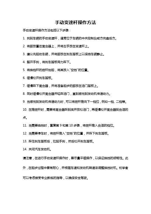
手动变速杆操作方法
手动变速杆操作方法包括以下步骤:
1. 找到车辆的手动变速杆,通常位于车辆的中央控制台或方向盘后方。
2. 将脚放置在离合器上,并将左手放在变速杆上。
3. 建议先起动车辆,并将脚放在刹车踏板上以保持车辆静止。
4. 解开手刹,将刹车踏板用力踩下。
5. 将换档杆的拨杆抬起,将其放入"空挡"的位置。
6. 缓慢松开刹车踏板。
7. 缓慢踩下离合器,并将准备起步的脚放在油门踏板上。
8. 同时缓慢松开离合器并轻踩油门,直到感觉到发动机传递动力。
9. 当感觉到发动机传递动力时,可以将拨杆推向下一档位,例如一档、二档等。
10. 在推拨杆时,需要将离合器踩到底并放松油门,再缓慢松开离合器到合适的点。
11. 当需要换挡时,重复第9和第10步骤,将拨杆推入合适的档位。
12. 当需要停车时,将拨杆推入"空挡"的位置,并踩下刹车踏板。
13. 踩住刹车踏板后,拉起手刹,然后松开刹车踏板。
14. 关闭汽车发动机。
请注意,在进行手动变速杆操作时,要尽量平缓操作,以保证换挡的顺畅性。
此外,在起步过程中要有耐心,并根据车速和发动机转速来调整换挡时机。
初学者可以考虑接受专业教练的指导,以确保安全驾驶。
手动变速箱操作指南说明书

The A/C is off, or in ECON mode, and the outside temperature is
above 41°F (5°C) (See pages 84, 93 ).
There is adequate vacuum reserve for the power brakes.
Driving 137
The manual transmission is synchronized in all forward gears for smooth operation. It has a lockout so you cannot shift directly from Fifth to Reverse. When shifting up or down, make sure you push the clutch pedal down all the way, shift to the next gear, and let the pedal up gradually. When you are not shifting, do not rest your foot on the clutch pedal. This can cause your clutch to wear out faster.
米切尔-手动变速器变速器分解与组装

Disassemble Mainshaft
After removing the 3-4 synchro. snap ring, 3rd gear and the 3-4 synchro. assembly are removed from the mainshaft. Note that the press plate is supporting 3rd gear as the shaft is forced downward, and that the tech. is ready to catch the mainshaft as it comes free.
Oil Cup
14
Mainshaft Assembly
Blocker Ring Synchronizer Sleeve
Speed Gear
When this mainshaft group is assembled, the synchro. Sleeves (green) must face the correct direction, each blocker ring (orange) must have free play, and each speed gear (blue) must have the proper end float.
Transmission Disassemble & Reassemble
1
Service Information
The best source of information concerning a particular transmission is usually the vehicle or transmission manufacturer’s service manual. Service information is also available from general manual sources like All Data or Motors as well as other printed, computerized, and online sources. This information normally contains important specifications and disassembly/ reassembly steps.
不同公路车变速操作方法
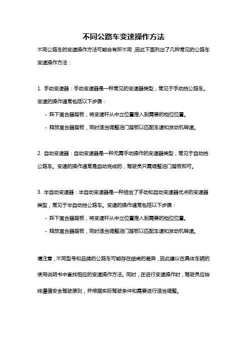
不同公路车变速操作方法
不同公路车的变速操作方法可能会有所不同,因此下面列出了几种常见的公路车变速操作方法:
1. 手动变速器:手动变速器是一种常见的变速器类型,常见于手动挡公路车。
变速的操作通常包括以下步骤:
- 踩下离合器踏板,将变速杆从中立位置推入到需要的档位位置。
- 释放离合器踏板,同时适当调整油门踏板以匹配车速和发动机转速。
2. 自动变速器:自动变速器是一种无需手动操作的变速器类型,常见于自动挡公路车。
变速的操作通常是自动完成的,驾驶员只需调整油门踏板即可。
3. 半自动变速器:半自动变速器是一种结合了手动和自动变速器优点的变速器类型,常见于半自动挡公路车。
变速的操作通常包括以下步骤:- 踩下离合器踏板,将变速杆从中立位置推入到需要的档位位置。
- 释放离合器踏板,同时适当调整油门踏板以匹配车速和发动机转速。
请注意,不同型号和品牌的公路车可能存在细微的差异,因此建议在具体车辆的使用说明书中查找相应的变速操作方法。
同时,在进行变速操作时,驾驶员应始终遵循安全驾驶原则,并根据实际驾驶条件和需要进行适当调整。
公路车变速器调整方法
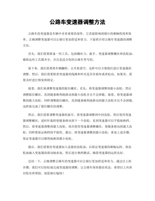
公路车变速器调整方法公路车的变速器是车辆中非常重要的部件,它直接影响到骑行的顺畅程度和效率。
正确调整变速器可以让骑行更加舒适和省力。
下面将介绍公路车变速器的调整方法。
首先,我们需要准备一些工具,包括螺丝刀、扳手、变速器调整螺丝和齿轮油。
确保这些工具都齐全,并且是适合你的公路车型号的。
接下来,我们需要将车辆翻转,让车轮悬空。
这样可以方便我们进行变速器的调整。
然后,我们需要检查变速器的线路和外壳是否有损坏或者松动。
如果有,需要及时进行修复和固定。
接着,我们来调整变速器的限位螺丝。
首先,将变速器调整到最小齿轮,然后调整限位螺丝,直到链条顺利地移动到最小齿轮并且不会掉链。
接着,将变速器调整到最大齿轮,同样调整限位螺丝,直到链条顺利地移动到最大齿轮并且不会掉链。
这样就完成了限位螺丝的调整。
然后,我们需要调整变速器的索引。
将变速器调整到中间齿轮,然后使用变速器调整螺丝,逆时针旋转使链条移动到下一个齿轮,直到变速器可以平稳地换档。
然后,将变速器调整到最大齿轮,再次使用变速器调整螺丝,使链条移动到最大齿轮,同样要保证换档的平稳性。
最后,将变速器调整到最小齿轮,重复上述步骤,保证变速器可以顺利地换到最小齿轮。
最后,我们需要给变速器加入适量的齿轮油,以保证变速器的顺畅运转。
将齿轮油滴入变速器的滑动轴承处,然后进行换档测试,确保变速器的运转良好。
总结一下,正确调整公路车的变速器可以让骑行更加舒适和省力。
通过以上的步骤,我们可以轻松地完成变速器的调整,让公路车保持最佳状态。
希望以上内容对您有所帮助,祝您骑行愉快!。
超实用汽车指南-手动变速器操作

超实用汽车指南-手动变速
器操作
复杂但灵活、技术先进
变速器负责通过齿轮改变发动机的运转速度并传递能量。
它分几个档,比如马力较强的低速档、转动快的高速档等,手动切换不同的档叫手动(MT)。
手动内部有两三个传动轴、几个齿轮。
成套的齿轮相互啮合,单只的齿轮围绕传动轴空转,同时选择并更替和传动轴一起旋转的齿轮。
但是齿轮一直在转,而齿轮在转动中无法顺利更换,所以必须通过离合器将动力阻断。
当然,在此之前有一个问题就是没有离合器车就没法前进。
离合器的两个旋转的圆盘啮合时传递动力,分离时阻断动力。
实际上这一过程是弹簧挤压与变速器相连的汽车离合器摩擦片,从而将动力传递到和发动机的曲柄轴相连的飞轮。
因此当踩下离合器踏板时,离合器摩擦片和飞轮分离,动力传递便会被阻断。
半离合器指的是离合器摩擦片分离过程中滑离的状态。
手动的操作很复杂,但从驾驶者能根据自己的意思选档这点来看,手动变速器可以说很灵活好用。
而且这种方式损耗较小,效率高,从技术角度看,手动也值得圈点。
差速器的检查与调整

2.齿轮是否转动灵活且有少量间隙
标准
小车 0.30mm 大车 0.60mm
极限
小车 0.60mm 大车 1.00mm
3.行星齿轮与行星齿轮轴间隙是否过大、标准0.10mm极限0.20mm
调整:
在半轴齿轮背面加垫片,间隙变小,反之变大。
课后作业:
差速器的更换步骤。
项目三:差速器的检查与调整
差速器的组成,转弯时驱动桥有异响, 经过修理工的检查判断是差速器出现了故障。
差速器哪里出现了故障呢?
在半轴齿轮背面加垫片,间隙变小,反之变大。
在在修修车 车厂厂1,,. 检有有一一查辆辆半汽汽车车轴直直齿行行时时轮无无和异异响响行,,星转转齿弯弯时时轮驱驱是动动桥桥否有有有异异响响掉,,齿经经过过修修理理工工的的检检查查判判断断是是差差速速器器出出现 现了了故故障障。。
差速器的更换步骤。 在半轴齿轮背面加垫片,间隙变小,反之变大。 项目三:差速器的检查与调整 行星齿轮与行星齿轮轴间隙是否过大、标准0. 齿轮是否转动灵活且有少量间隙 齿轮是否转动灵活且有少量间隙 差速器的更换步骤。 差速器的更换步骤。 差速器哪里出现了故障呢? 差速器哪里出现了故障呢? 差速器的更换步骤。 差速器哪里出现了故障呢? 在半轴齿轮背面加垫片,间隙变小,反之变大。 在半轴齿轮背面加垫片,间隙变小,反之变大。 在修车厂,有一辆汽车直行时无异响,转弯时驱动桥有异响,经过修理工的检查判断是差速器出现了故障。 行星齿轮与行星齿轮轴间隙是否过大、标准0. 差速器的更换步骤。 行星齿轮与行星齿轮轴间隙是否过大、标准0. 齿轮是否转动灵活且有少量间隙 行星齿轮与行星齿轮轴间隙是否过大、标准0. 差速器哪里出现了故障呢? 检查半轴齿轮和行星齿轮是否有掉齿 项目三:差速器的检查与调整 齿轮是否转动灵活且有少量间隙 在半轴齿轮背面加垫片,间隙变小,反之变大。 项目三:差速器的检查与调整 在修车厂,有一辆汽车直行时无异响,转弯时驱动桥有异响,经过修理工的检查判断是差速器出现了故障。
差速器调整

3311E差速器安装及调整差速器有三种功能:1。
它可增加传动轴传递的扭矩。
2.将扭矩传递给驱动半轴。
3.使驱动轮在不同的速度下转动。
一、分解差速器:1.分解前在壳体和轴承座及轴承调节器作出识别记号。
2.拆除锁紧钢丝拆下螺栓和卡锁。
3.拆下轴承座圈螺栓、轴承座圈和轴承调节器。
拆下齿圈总成。
4.在拆除固定法兰座时作出识别记号。
拆下齿圈固定法兰座的八个螺栓,使固定法兰座和壳体分开。
5.将十字轴和十字轴行星齿轮从固定法兰座提出,并取出侧齿轮及止推垫圈。
6.在拆轴承座圈和差速器壳体前作出识别记号。
7.拆除螺栓、压板和密封圈拿下叉头总成。
8.拆除轴承座圈螺栓,拆下轴承座圈及调隙片。
9.用吊具提出小齿轮组件。
二、清洗检查差速器:1.清洗差速器的零件,检查零件的磨损,对磨损过量的零件及时更换。
2.检查轴承座圈座毂的外机加表面与轴承座孔的同轴度应在0.05㎜(0.002英寸)之内。
3.检查轴承座圈的外机加表面与油封的同轴度应在0.05㎜(0.002 英寸)之内。
4.检查轴承座圈和壳体上的螺纹与孔的同轴度应在0.27㎜(0.005英寸)之内,并与小齿轮轴孔相垂直,并从小齿轮轴的孔中心线254㎜处检查,垂直度应在0.08㎜(0.003英寸)之内。
5.壳体和法兰座的机加配合表面与轴线相垂直,其垂直度应在0.08㎜(0.003英寸)之内,二者组装后配合孔的同心度应在0.08㎜(0.003英寸)之内。
三、轴承间隙测量:1.确定轴承座的调隙片厚度。
a.在壳体内的小齿轮轴承孔内安装一组约厚1.5㎜(0.06英寸)的调隙片,作为尺寸“X”。
b.将小齿轮总成与轴承座圈装入壳体,并用八个螺栓等距离将轴承座圈紧固。
c.转动小齿轮并紧螺栓直到小齿轮不能用手转动为止。
d.将一个大约450㎜(18英寸)长的平板放在壳体内的两个轴承座安装平面上。
e.测量从小齿轮轴端的中心位置到平板下表面的距离,作为尺寸“A”。
f.记录刻在小齿轮端部尺寸,作为尺寸“B”。
- 1、下载文档前请自行甄别文档内容的完整性,平台不提供额外的编辑、内容补充、找答案等附加服务。
- 2、"仅部分预览"的文档,不可在线预览部分如存在完整性等问题,可反馈申请退款(可完整预览的文档不适用该条件!)。
- 3、如文档侵犯您的权益,请联系客服反馈,我们会尽快为您处理(人工客服工作时间:9:00-18:30)。
Carrier Bearing Preload
Shim
A shim is being inserted between the right side bearing cup and the housing. The thickness of this (right side) shim and the left side shim will determine carrier bearing preload and back lash. Carrier bearing preload occurs when the shims are thicker than the space.
10
Contact Pattern
Gear Marking Compound Face Flank
Pinion Tooth Contact
To check gear contact, a thin film of gear marking compound is painted onto the tooth, and the gears are rotated. The rubbing action of the pinion gear should wipe off a contact area that is about one-half the length of the tooth.
Pinion Depth
Shim Shim
Pinion Preload
Shims
Collapsible Spacer
3
Crush Sleeve
Nut Crush Sleeve
The collapsible spacer, commonly called a crush sleeve, fits between the upper bearing and the lower bearing or gear. Tightening the pinion shaft nut collapses the sleeve and increases the preload on the bearings. A new crush sleeve is used when the pinion gear is installed.
Adjust Ring & Pinion Gears
1
Carrier Adjustments
Carriers require four major adjustments during assembly: 1. Pinion bearing preload 2. Pinion depth 3. Carrier bearing preload 4. Backlash
6
Replacing Differential
Differential Case
Carrier
Shim
The differential and ring gear with the carrier bearings has been placed into the carrier with the ring gear contacting the pinion gear. An adjusting shim is being inserted between the left bearing cup and the housing.
is at the inner end. The pinion gear exerts driving pressure on
the more vertical convex side of the tooth while the more
slanted, concave side is called the coast side.
2
Pinion Gear Adjustments
Most pinion preload adjustments are made using a collapsible spacer; some use selective shims.
Most pinion depth shims are between the gear head and the bearing; some fit between the bearing cup and the carrier.
8
king Back Lash
Flexible Mount
The dial indicator is set up using a flexible mount. The measuring stylus is against a ring gear tooth. Back lash is read on the dial indicator by rocking the ring gear back and forth while holding the pinion gear stationary.
4
Checking Preload
Low-reading Torque Wrench
The amount of torque required to rotate the pinion gear is being measured using a low-reading torque wrench. If the amount is too low, the pinion nut will be tightened further to put more preload on the bearings.
5
Shim Adjustment
Pinion Gear
Pinion Preload Shims
A group of shims are placed between a step on the pinion shaft and the bearings. Thinner shims will increase the amount of bearing preload.
Dial Indicator Ring Gear
9
Ring Gear Tooth Names
Heel Toe
Coast Side: Concave
Drive Side: Convex
The heel is the outer end of the ring gear tooth, and the toe