tuv光伏线标准
光伏电缆的性能要求概要
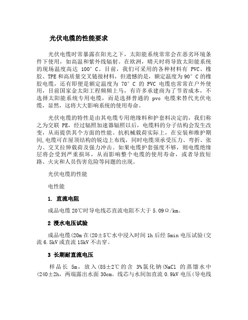
光伏电缆的性能要求光伏电缆时常暴露在阳光之下,太阳能系统常常会在恶劣环境条件下使用,如高温和紫外线辐射。
在欧洲,晴天时将导致太阳能系统的现场温度高达100°C。
目前,我们可采用的各种材料有PVC、橡胶、TPE和高质量交叉链接材料,但遗憾的是,额定温度为90°C的橡胶电缆,还有即便是额定温度为70°C的PVC电缆也常常在户外使用,目前国家金太阳工程频频上马,有许多承建商为了节省成本,不选择太阳能系统专用电缆,而是选择普通的pvc电缆来替代光伏电缆,显然,这将大大影响系统的使用寿命。
光伏电缆的特性是由其电缆专用绝缘料和护套料决定的,我们称之为交联PE,经过辐照加速器辐照以后,电缆料的分子结构会发生改变,从而提供其个方面的性能。
抗机械载荷实际上,在安装和维护期间,电缆可在屋顶结构的锐边上布线,同时电缆须承受压力、弯折、张力、交叉拉伸载荷及强力冲击。
如果电缆护套强度不够,则电缆绝缘层将会受到严重损坏,从而影响整个电缆的使用寿命,或者导致短路、火灾和人员伤害危险等问题的出现。
光伏电缆的性能电性能1. 直流电阻成品电缆20℃时导电线芯直流电阻不大于5.09Ω/km。
2 浸水电压试验成品电缆(20m在(20±5℃水中浸入时间1h后经5min电压试验(交流6.5kV或直流15kV不击穿。
3 长期耐直流电压样品长5m,放入(85±2℃的含3%氯化钠(NaCl的蒸馏水中(240±2h,两端露出水面30cm。
线芯与水间加直流0.9kV电压(导电线芯接正极,水接负极。
取出试样后进行浸水电压试验,试验电压为交流1kV,要求不击穿。
4 绝缘电阻成品电缆20℃时绝缘电阻不小于1014Ω·cm,成品电缆90℃时绝缘电阻不小于1011Ω·cm。
5 护套表面电阻成品电缆护套表面电阻应不小于109Ω。
其他性能1. 高温压力试验(GB/T 2951.31-2008 温度(140±3℃,时间240min, k=0.6,压痕深度不超过绝缘与护套总厚度的50%。
TUV 2Pfg1169光伏线标准

2 Pfg 1169/08.2007 Requirements forcables for use in photovoltaic-systemsContentsSeite Foreword (3)1Scope (3)2Normative references (3)3Terms and definitions (5)4Halogen-free PV-cable (6)4.1Code designation (6)4.2Characteristics (6)4.3Construction (6)4.4Test (8)4.5Guideline for use (informative) (8)4.6Current carrying capacity (8)Annex A (normative) Test of mutual influence (15)Annex B (normative) Test of absence of halogen (16)Annex C (normative) Determination of halogens – Elemental test (17)Annex D (normative) Test of long term resistance of insulation to D.C (19)Annex E (normative) Cold impact test (20)Annex F (normative) Dynamic penetration test (21)Annex G (normative) Notch propagation (23)Figure 1 – Arrangement of marking (8)Figure F.1 – Arrangement for penetration test (22)Table 1 – Current carrying capacity of PV-cables (9)Table 2 – Conversion factor for deviating temperatures (9)Table 3 – Tests for halogen free PV-cable (10)Table 4 – Requirements for halogen free insulation and sheath compounds (13)Table A.1 – Requirements (15)Table B.1 – Test method, measurement, requirements (16)Table B.2 – Test sequence (16)Table E.1 – Parameter for cold impact test (20)ForewordThis test specification contents the requirements listed in a manuscript of the working group AK 411.2.3 …Leitungen für PV-Systeme“ of the German committee for standardization (DKE). This manuscript is intended to be published as German pre-standard. Up to the date of publishing of the pre-standard this test-specification of TUV Rheinland will be used for test and assessment of cables for use in PV-systems (PV-cables).1 Scope2 PfG 1169/08.2007 applies to flexible single-core cables (cords) for use at the DC-side of photovoltaic-systems with a maximum permissible voltage of DC 1,8 kV (conductor/conductor, non earthed system). The cables are suitable for use in safety class II.It is permitted to connect these cables as multiple-construction.The cables are intended to operate at ambient temperature until 90°C2 Normative referencesThe following referenced documents are indispensable for the application of this document. For dated references, only the edition cited applies. For undated references, the latest edition of the referenced document (including any amendments) applies.IEC 60364-5-52, Erection of low voltage installations –Part 5: Selection and erection of electrical equipment –Chapter 52: Wiring systemsEN 50267-2-1, Common test methods for cables under fire conditions – Tests on gases evolved during combustion of materials from cables – Part 2-1: Procedures – Determination of the amount of halogen acid gas;EN 50267-2-2, Common test methods for cables under fire conditions – Tests on gases evolved during combustion of materials from cables – Part 2-2: Procedures – Determination of degree of acidity of gases for materials by measuring pH and conductivity;EN 50305, Railway applications – Railway rolling stock cables having special fire performance – Test methodsEN 50395, Electrical test methods for low voltage energy cables;EN 50396, Electrical test methods for low voltage energy cables;EN 60068-2-78, Environmental testing - Part 2-78: Tests -Test Cab: Damp heat, steady state (IEC 60068-2-78)EN 60216-1, Electrical insulating materials - Properties of thermal endurance - Part 1: Ageing procedures and evaluation of test results (IEC 60216-1);EN 60216-2, Electrical insulating materials – Thermal endurance properties – Part 2: Determination of thermal endurance properties of electrical insulating materials – Choice of test criteria (IEC 60216-2);EN 60228, Conductor of insulated cables (IEC 60228)EN 60332-1-2, Tests on electric and optical fibre cables under fire conditions – Part 1-2: Test for vertical flame propagation for a single insulated wire or cable – Procedure for 1 kW pre-mixed flame; (IEC 60332-1-2)EN 60684-2, Flexible insulating sleeving – Part 2: Methods of test (IEC 60684-2)EN 60811-1-1, Insulating and sheathing materials of electric cables – Common test methods Part 1-1: General application – Measurement of thickness and overall dimensions – Test for determining the mechanical properties (IEC 60811-1-1)EN 60811-1-2, Insulating and sheathing materials of electric and optical cables – Common test methods. Part 1-2: General application. Thermal ageing methods (IEC 60811-1-2)EN 60811-1-3, Insulating and sheathing material of electric and optical cables – Common test methods – Part 1-3: General application – Methods for determining the density – Water absorption tests – Shrinkage test (IEC 60811-1-3)EN 60811-1-4, Insulating and sheathing materials of electric and optical cables – Common test methods. Part 1-4: General application. Tests at low temperature. (IEC 60811-1-4)EN 60811-2-1, Insulating and sheathing materials of electric and optical cables – Common test methods – Part 2-1: Methods specific to elastomeric compounds – Ozone resistance, hot set and mineral oil immersion tests (IEC 60811-2-1)EN 60811-3-1, Insulating and sheathing materials of electric cables – Common test methods Part 3-1: Methods specific to PVC compounds – Pressure test at high temperature, test for resistance to cracking (IEC 60811-3-1)HD 22.13, Rubber insulated cables of rated voltages up to and including 450/750 V Part 13: Single and multicore flexible cables, insulated and sheathed with crosslinked polymer and having low emission of smoke and corrosive gases;HD 605, Power cables – Part 605: Additional test methodsHD 60364-7-712Electrical installations of buildings – Part 7-712: Requirements for special installations or locations – Solar photovoltaic (PV) power supply systems (IEC 60364-7-712, modified)3 Terms and definitionsFor the purposes of this document, following definitions apply.3.1 Terms for test procedure3.1.1Type test (symbol T)Tests required to be made before supplying a type of cable covered by this standard on a general commercial basis, in order to demonstrate satisfactory performance characteristics to meet the intended application. These tests are of such a nature that, after they have been made, they need not be repeated, unless changes are made in the cable materials or design or manufacturing process which might change the performance characteristics.3.1.2sample tests (symbol S)Tests made on samples of completed cable or components taken from a completed cable, at a specified frequency, so as to verify that the finished product meets the specified requirements.3.1.3Routine tests (symbol R)Tests made by the manufacturer on each manufactured length of cable to check that each length meets the specified requirements3.2Rated voltageThe rated voltage of the cable determines the construction and the tests of the cable with regard to the electrical properties.The rated voltage is designated by two values of frequency voltage: U0/U in VoltU0 rated power frequency voltage between conductor and earth (metallic screen of cable or ambient medium);U rated power frequency voltage between two conductors of a multipole cable or of a system of single core cables.The rated voltage of the cable for a given application shall be suitable for the operating conditions in the system in which the cable is used.This requirement is applicable for both U o and UThe rated voltage between two conductors in a DC-system shall not exceed the 1,5 time value of rated voltage U of the cable, and the rated voltage between conductor and earth shall not exceed the 1,5 time value of rated voltage U o of the cable.NOTE The operating voltage of a system may exceed is rated voltage permanent for 20%. A cable may be operated with a voltage which value is 20% higher than rated voltage under condition that the rated voltage is not less than the rated voltage of the system.3.3DC sidepart of a PV installation from a PV cell to the DC terminals of the PV inverter3.4open-circuit voltage under standard test conditions U OC STCvoltage under standard test conditions across an unloaded (open) PV module, PV string, PV array, PV generator or on the DC side of the PV inverter3.5short-circuit current under standard test conditions I SC TCshort-circuit current of a PV module, PV string, PV array or PV generator under standard test conditions4 Halogen free PV-cable4.1 Code designationPV1-F4.2 Characteristics4.2.1 Rated voltageAC U0/U 0,6/1 kVDC 1,8 kV (conductor-conductor, non earthed system, circuit not under load).If the cable is used in DC-systems the rated voltage between two conductors shall not exceed the 1,5 time value of rated voltage U of the cable. In with single-phase earthed DC-systems this value shall be multiplied with factor 0,5.4.2.2 Temperature rangeAmbient temperature: –40 °C to +90 °CMax. temperature at conductor: 120 °CThe cables are intended to operate at ambient temperature until 90°C. For this a temperature index of 120°C applies to the insulation and the sheath, bas ed on EN 60216-1 (20.000h, 50% residual elongation). Note The expected period of use is 25 years.The permitted short-circuit-temperature refer to a period of 5s is 200°C.4.3 Construction4.3.1 ConductorNumber of conductors: 1The conductor shall be class 5, according to EN 60228.The single wires must be tinned.Preferred diameters: 2,5, 4, 6, 10, 16 mm24.3.2 Separation layerA separation layer of a suitable halogen free material may be applied around the conductor.4.3.3 InsulationThe insulation shall be a suitable halogen free material applied around the conductor.The insulation shall be extruded and shall consist of one or several adjacent adherent layers. It shall be solid and homogeneous, it must be possible to remove it without damage to the insulation itself, to the conductor and to the tin coating.The insulation shall be smooth, consistently applied and largely circular. Compliance shall be checked by inspection and by manual test.The wall thickness of insulation is specified by the manufacturer, but it must not fall short of the minimum value of 0,5mm.4.3.4 Separation layerA separation layer of a suitable halogen free material may be applied around the insulation.4.3.5 SheathThe core must be covered by a sheath.The sheath around the core must be of a suitable halogen free material.The sheath shall be extruded and shall consist of one or several adjacent adherent layers. The sheath shall be smooth and consistently applied.The wall thickness of sheath is specified by the manufacturer, but it must not fall short of the minimum value of 0,5mm.4.3.6 Outer diameterThe average value of the outer diameter shall be within the limits specified by the manufacturer.4.3.7 Multiple constructionEach single-core cable in a multiple construction shall pass the requirements of this document. Each additional component in a multiple construction shall pass the requirements of this document.4.3.8 Marking4.3.8.1 GeneralThe cable shall be marked as follows:a) Trademark;b) Code designation;c) Rated diameter.Marking may be by printing or by reproduction in relief on or in the sheath.4.3.8.2 TrademarkCables shall be provided with an indication of the manufacturer, which consist of a consecutively marking with company name or company sign or with (if trademarked) an identification number.4.3.8.3 Code designationCables shall be provided with an code designation according to 4.1 applied consecutively on sheath.4.3.8.4 Arrangement of markingEach marking is considered as consecutive if the spacing between the end of a marking and the begin of the following identical marking does not exceed following value:– 550mm, for marking on sheath or outer jacket.Following figure shows an example of marking on sheath.Figure 1 – Arrangement of marking4.3.8.5 DurabilityPrinted markings shall be durable. Compliance with this requirement shall be checked by the test given in 5.1 of EN 50396.4.3.8.6 LegibilityEach marking shall be legible.4.4 TestCompliance with the requirements of 4.3 shall be checked by visual inspection and tests according to table3.4.5 Guideline for use (informative)Cables according to this standard are intended for use in PV-systems according to EN 60364-7-712.4.6 Current carrying capacityAmbient temperature: 60°CMax. temperature at conductor: 120 °CTable 1 – Current carrying capacity of PV-cablesKind of installationRated diameter Single cable free inair Single cable onsurfacesTo cables adjacent onsurfacesmm2 A A A1,5 30 29 242,5 41 39 334 55 52 446 70 67 5710 98 93 7916 132 125 10725 176 167 14235 218 207 176Table 2 – Conversion factor for deviating temperaturesAmbient temperature Conversion factor°CUp to 60 1,0070 0,9180 0,8290 0,71100 0,58110 0,41Reduction factor for accumulation according to IEC 60364-5-52, Table B.52-17Table 3 – Tests for halogen free PV-cable1 23 45Test method described in Ref. No. TestRequirementsCategory of teststandardclause1 Electrical tests1.1 Resistance of conductorsT,S EN 50395 5 1.2 Voltage test on completed cable with AC or DC T,S EN 503956– AC-test-voltage kV– DC- test-voltage kV Length of sample m Duration of testmin Temperature of the water°C 6,5 15 20 5 20 ± 5 1.3 Absence of faults at complete cable – AC-test-voltage kV 10 R EN 50395 10 1.4Surface resistance of sheath – Minimum value Ω109 TEN 50395111.5Insulation at complete cable Length of sample m Duration of testh Temperature of the water °C – Minimum value at 20 °C Ω ⋅ cm – Minimum value at 90 °CΩ ⋅ cm5 2 20± 5 1014 1011 T EN 50395 81.6 Long term resistance of insulation to d.c. T Annex D2 Constructional and dimensional tests2.1 Checking of compliance with constructional provisionsT,S Inspection and manual tests2.2 Measurement of thickness of insulation T,S EN 50396 4.1 2.3 Measurement of thickness of sheath T,S EN 503964.2 2.4 Measurement of overall dimensions 2.4.1 – Mean valueT,S EN 50396 4.4 2.4.2 –Ovality%≤ 15 T,S EN 50396 4.4 3 Pressure test at high temperature at complete cable T EN60811-3-13.1 Test conditions:– temperature°C 140 ± 3 – duration of heating under load min240 – Coefficient k 0,6 3.2 Results to be obtained:– depth of penetration, max.%50 – Voltage test 10 min after exculpation andcoolingTable 4, 1.24 Damp heat test T EN 60068-2-784.1 Test conditions:– temperature °C 90 – duration h 1000 – relative humidity %85 4.2 Results to be obtained:– variation of tensile strength max. % – 30– variation of elongation at breakmax. %– 30No. Test Requirementsof test standard clause5 Resistance against acid and alkalinesolutionT EN 60811-2-1 10 5.1Chemical stressacid: N-Oxal-acidalkaline solution: N-sodium hydroxide solutiontemperature °C 23duration h 1685.2Tensile strength:variation, max. % ± 305.3Elongation at break, min. % 1006 Test of influence T Annex A7 Cold impact test at –40 °C T Annex E8 Cold bending testDiameter of cable < 12,5 mmT EN 60811-1-4 8.2 8.1 Test conditions:– temperature °C –40 ± 2– duration of conditioning h 16 EN 60811-1-4 8.2.3 8.2 Results to be obtained Absence ofcracks9 Cold elongation testDiameter of cable ≥ 12,5 mmTable 3 10 Ozone resistance at complete cable T10.1 Method B EN 50396 8.1.3– temperature °C 40 ± 2– relative humidity % 55 ± 5– duration h 72– Ozone concentration %(by volume)(200 ± 50) × 10–610.2 Results to be obtained Absence ofcracks.11 Weathering/UV-resistance T HD 605/A1 2.4.20 11.1 Conditions:– duration h 720– temperature °C(Black-Standard-temperature)63– relative humidity % 65– min. power at W/m2wavelength 300 nm to 400 nm60 ± 2– duration spraying/drying min 18/102Results to be obtained Absence ofcracks.12 Dynamic penetration test T Annex F13 Notch propagation T Annex GNo. Test Requirementsof test standard clause14 Shrinkage test at complete cable T EN 60811-1-3 11((sheath)) 14.1 Conditions:– temperature °C 120– duration h 1– Distance L of sample mm 30014.2 Results to be obtained:– Maximum shrinkage. % 215 Test under fire conditions15.1 Test for vertical flame propagation at completecableT, S EN 60332-1-215.2 Assessment of halogen T, S15.2.1 Absence of halogen Annex B 15.2.2 Determination of halogens – Annex CTable 4 – Requirements for halogen free insulation and sheath compounds1 2 3 4 5 6 7Test method described in Type of compoundRef. No. Test Unitstandard clause insulation sheath1 Mechanical characteristics1.1 Properties before ageing EN 60811-1-1 9.21.1.1 Values to be obtained for the tensile strength:– median, min. N/mm26,5 8,01.1.2 Values to be obtained for the elongation atbreak:– median, min. % 125 125 1.2 Properties after ageing in oven EN 60811-1-2 8.11.2.1 Ageing conditions:– temperature °C 150 ± 2 150 ± 2 – duration of treatment h 7 × 24 7 × 24 1.2.2 Values to be obtained for the tensile strength:c– median, min. N/mm2– – – variation, max. % –30a–30a1.2.3 Values to be obtained for the elongation atbreak:c– median, min. % – – – variation, max. % – 30a– 30a 1.3 Hot set test d EN 60811-2-1 91.3.1 Conditions– Temperature °C 200± 3 200± 3 – Time under load min 15 15 – mechanical stress N/cm220 20 1.3.2 Values to be obtained– elongation under load, max. % 100 100 – permanent elongation after cooling, max. % 25 25 1.4 Thermal endurance properties EN 60216-21.4.1 ConditionsEither test of elongation at break or bending testshall be performed.– Temperature index 120 120 – elongation at break c% 50 50 – bending test EN 50305 7.2 2 D 2 D 1.5 Cold elongation test EN 60811-1-4 8.41.5.1 Conditions:– temperature °C –40 ± 2 –40 ± 2 – duration h EN 60811-1-4 8.4.4 und 8.4.5 b b 1.5.2 Values to be obtained:– elongation at break, min. % 30 301 2 3 4 5 6 7Test method described in Type of compoundRef. No. Test Unitstandard clause insulation sheatha No positive value for variation fixed.b See test method in column 4 and 5.c This test shall be performed at test samples of insulation and sheath compound.d This test shall be performed only at cross-linked insulation and sheath compoundTest of mutual influenceA.1 ConditionsTest samples must be aged for 7 days at (135 ± 2) °C at conditions according to table 2A.2 RequirementsAfter ageing the insulation and the sheath shall pass the requirements of table A.1.Table A.1 – RequirementsTests units insulation sheathTensile strength – median, min. N/mm2– –– variation a, max. % ± 30 –30 b Elongation at break – median, min. % – –– variation a, max. % ± 30 ± 30a Variation: difference between the median value obtained after ageing and the median value obtained without ageing expressed as apercentage of the latter.b Positive tolerances are not limited.Test of absence of halogenB.1 Requirements of extruded materialsInsulation and sheath shall pass the requirements as follows: a) Type testThe material must be tested as described in table B.1.Table B.1 – Test method, measurement, requirementsTest methodMeasurementrequirements1 EN 50267-2-2 pH and conductivity pH ≥ 4,3 undconductivity ≤ 10 µS/mm a 2 EN 50267-2-1 Chlorine- and Bromine content, expressed in HCI ≤ 0,5 %3aAnnex CHalogen: FluorideIf negative the test should be finished. No further test is necessary.The material shall be accepted.If positive, test of 3b shall be performed 3bEN 60684-2Fluoride content≤ 0,1 %a If discrepancies regarding conductivity appear, e.g. the recommended value is exceeded even if there is compliance with therecommended ph-value, other test method may be applied after agreement with all participants.b) Selection testThe material shall be tested according to test sequence of table B.2.Table B.2 – Test sequenceTest method MeasurementValue ResultIf negative the test should be finished. No further test is necessary.The material shall be accepted. Phase 0 HD 22.13,Annex CHalogen: Fluoride, Chloride and BromideIf positive continue with phase 1.< 4,3 The material shall be revised. pH ≥ 4,3Conductivity shall be tested. conductivity ≤ 2,5 µS/mmThe material shall be accepted. No further test is necessary.conductivity > 10 µS/mm The material shall be revised.Phase 1 EN 50267-2-2 conductivity (s)> 2,5 µS/mm but ≤ 10 µS/mm Test according to EN 50267-2-1 shall be performed > 0,5 % The material shall be revised.Phase 2 EN 50267-2-1Chlorine- and Bromine content, expressed in HCI≤ 0,5 % Test according to EN 60684-2 shall be performed. > 0,1 % The material shall be revised. Phase 3 EN 60684-2Fluoride content≤ 0,1 %The material shall be accepted.Determination of halogens – Elemental testWarningOwing to its potentially hazardous nature, the fusion operation should be carried out in a fume cupboard, using a safety screen.C.1 EquipmentBunsen burner3 small/medium soda glass test tubes (approximately 50 mm x 10 mm)Test tube holderEvaporating basin/mortarWire gauze;FunnelFilter paperC.2 MaterialsUnknown sampleSodium metalDilute nitric acid (5 %)Aqueous silver nitrate (5 %)Dilute ammonia (10 %)Freshly made up zirconium-alizarin red S reagentGlacial acetic acidAcid/pH indicator papersC.3 ProcedureC.3.1 Sodium fusionPlace 200 mg – 250 mg of the sample into the bottom of a small soda glass test tube. Add 10 ml of distilled/de-ionized water to the evaporating basin and place this in the fume cupboard behind the safety screen. Whilst holding the test tube firmly with the test tube holder at an angle of 45° - 60° to the vertical, introduce a piece of freshly cut, clean sodium (about the size of a small pea) (200 mg – 250 mg) into the mouth of the test tube without allowing it to come into contact with the sample. With the safety screen in place, heat the sodium gently until it melts and runs down on to the sample (there may be a vigorous reaction when the molten sodium reaches the sample if halogens are present). Heat the tube gently for about 1 min, then more strongly until the lower 20 mm of the tube glows red hot. Plunge the red hot tube into the water in the evaporating basin, immediately placing the gauze on top. (The gauze prevents any loss of material when the tube shatters on contact with the water.) Allow any non reacted sodium to react before grinding up the solution and glass. Filter, and separate the filtrate into two equal portions.C.3.2 Chlorine and bromineTo the first portion of the filtrate, add sufficient nitric acid to make the solution acidic. Boil this solution until its total volume has been reduced by half (this is to remove any HCN or H2S, if present, which would interfere with the test). Add 1 ml silver nitrate solution; a white or yellowish-white precipitate indicates the presence of halogen (Cl, Br) in the original sample. (If the liquor is decanted, and the precipitate is white and readily soluble in dilute ammonia, then chloride is present.)C.3.3 FluorineTo the second portion of the filtrate, acidify with glacial acetic acid. Boil this solution until its total volume has been reduced by half. Add 2 to 3 drops freshly prepared zirconium lake reagent (equal volumes of: a) Alizarin solution: 0,05 g Alizarin Red-S in 50 ml distilled water, b) Zirconium solution: 0,05 g zirconium nitrate in 10 ml concentrated HCl diluted with 50 ml distilled water). Heat at 40 °C for 1 h. The presence of fluoride is indicated by the red/pink colouration being bleached to yellow.Test of long term resistance of insulation to D.C.A test sample with a length of minimum 5m shall be immersed into water containing 3 % NaCl. Further on minimum 300mm of the sample shall stick out of the water. The water-bath shall be retained for (240 ± 2) h at a high temperature of (85 ± 2) °C and a D.C.-vol tage 0,9kV shall be applied between conductor and water whereby the conductor shall be connected to the positive potential.The current of this circuit shall be measured with a period of not more than 24h. If possible a continuous measurement shall be preferred.The measured values shall be recorded in a time-current-curve which identifies a stable progress.NOTE A stable progress is e.g. an increase of less than 10% of leakage current on the average for a time of 24h (This is part of the inspection based on practical experiences)After storing the samples shall be taken out of the salt-water-solution and a voltage test according to Ref.-No. 1.2 of table 1 shall be performed. The test voltage shall be the rated voltage (U) of the cable.Cold impact testThe cold impact test shall be performed at –40°C ac cording to clause 8.5 of EN 60811-1-4, but the mass of hammer, the mass of test probe and the height shall comply with table 2.Table E.1 – Parameter for cold impact testDiameter of cable (D) Mass of hammer Mass of test probe height mm g g mmD < 15 1 000 200 10015 < D≤ 25 1 500 200 150D > 25 2 000 200 200The inner and outer surface of sheath shall be inspected with normal or corrective visual faculty without magnification. Only the outer surface of the insulation shall be inspected. No cracks must be determinedAnnex F(normative)Dynamic penetration testA test apparatus for pull test (or a equivalent apparatus) shall be operated in pressure modus and shall be equipped with a measuring device which is able to record the force of penetration of the spring-steel-needle (see figure F.1b) through the insulation or sheath of a completed cable. A circuit with low voltage which finish the test at the moment when the needle penetrates the insulation or the sheath and makes contact with the conductor shall be added.The test shall be performed at room temperature. The force applying to the needle shall be increased continuously with 1 N/s until contact with the conductor has been made. 4 tests at each sample shall be performed and the force at the moment of contact shall be recorded. After each test the sample shall be moved forward and shall be turned clockwise for 90°.The mean value of the 4 test results must not be less than the minimum value F determined with following formulaF = 50 ⋅DD diameter of cable in mmDimensions in mma) detail X(edges not broken or rounded, without ridge)b) detail YCaption 1 N.A. 2 N.A. 3 Load 4 Clamp 5 Sample6Mounting surface7 Fixing screw 8 Blade9 Shoulder with sufficient depth for testing the insulation 10 Needle of spring steel 11SampleFigure F.1 – Arrangement for penetration test。
光伏电缆标准-译文
2 Pfg 1169/08.2007 光伏系统中电缆应用要求目录页码前言 (3)1 范围 (3)2 规范性附录 (3)3 术语和定义 (5)4 无卤素光伏电缆 (6)4.1 规定牌号 (6)4.2 特征 (6)4.3 结构 (6)4.4 试验 (8)4.5 使用指南(参考) (8)4.6 载流能力 (8)附录 A (规范性附录)影响试验 (15)附录 B (规范性附录)无卤素试验 (16)附录 C (规范性附录)卤素的测定–元素试验 (17)附录 D (规范性附录).长期耐绝缘DC的试验方法 (19)附录 E (规范性附录)冷冲击试验 (20)附录 F (规范性附录) 动力触探试验 (21)附录 G (规范性附录) 凹槽扩散 (23)图1 –标记的安排 (8)图F.1 –穿透试验的安排 (22)表1 –光伏电缆的载流能力 (9)表2 – (9)表3 –无 (10)表4 - (13)表A.1 –要求 (15)表B.1 –试验方法、测量、要求 (16)表 B.2 –试验顺序 (16)表 E.1 –冷冲击试验的参数 (20)前言本试验规范的内容在一个工作组稿件支AK列出的要求411.2.3“Leitungen献给光伏系统有限公司”的德国标准化委员会(DKE)。
此手稿是拟作为德国前标准公布。
截至会前,这个测试标准,德国TUV莱茵规范的出版日期将被用于测试和评估中的电缆光伏系统(光伏电缆)的使用。
1.范围2 PfG 1169/08.2007适用于光伏系统直流侧使用的单芯软电缆(软线),其最大可允许电压为1.8千伏直流(导体-导体,不接地系统)。
电缆适合用于安全等级II的情况。
允许以多结构的方式,将这些电缆连接起来。
该电缆的设计目的是用于在室温下操作,最高温度可达90℃。
2.规范性文献以下引用的文件是使用本文件必不可少的部分。
凡是注日期的引用文献,只有被引用的版本才适用。
凡是不注日期的引用,该引用的文件(包括任何修订)的最新版本应适用。
光伏电缆标准

光伏电缆标准光伏电缆是指用于太阳能光伏发电系统中的电缆,其主要作用是将太阳能电池板产生的直流电输送到逆变器或直接连接到负载。
光伏电缆的选用对于太阳能发电系统的安全、可靠和高效运行至关重要。
因此,制定和执行光伏电缆标准显得尤为重要。
首先,光伏电缆标准需要明确规定电缆的选材要求。
光伏电缆在户外使用,需要具备耐候性和耐紫外线能力,因此在材料选择上需要考虑到这些因素。
另外,光伏电缆还需要具备良好的绝缘性能和耐磨损能力,以确保在户外恶劣环境下能够长期稳定运行。
其次,光伏电缆标准需要明确规定电缆的结构和工艺要求。
光伏电缆通常需要经过埋地、架空等环境,因此在结构上需要具备一定的抗拉强度和耐压能力。
此外,电缆的接头处需要采用防水、防腐蚀的工艺,以确保在潮湿的环境下不会出现漏电、短路等安全隐患。
再次,光伏电缆标准需要明确规定电缆的安装和使用要求。
光伏电缆的安装需要符合国家电气规范,并且需要经过专业人员的施工。
在使用过程中,需要定期进行电缆的检查和维护,及时发现并处理电缆存在的问题,确保系统的安全运行。
最后,光伏电缆标准还需要明确规定电缆的检测和验收要求。
在光伏电缆安装完成后,需要进行电缆的耐压测试、绝缘电阻测试等,以确保电缆的质量和安全性。
同时,还需要进行电缆的验收,确保安装符合标准要求,并且能够正常运行。
总之,光伏电缆标准的制定和执行对于太阳能光伏发电系统的安全和高效运行至关重要。
只有严格执行标准要求,才能够保证光伏电缆的质量和安全性,从而推动太阳能发电行业的良性发展。
希望相关部门能够加强对光伏电缆标准的制定和执行,为我国太阳能发电行业的发展做出更大的贡献。
光伏发电系统专用电缆产品认证技术规范
CQC XXXX-2013光伏发电系统专用电缆产品认证技术规范Product Certification Criteria for Cable Applied Photovoltaic Power Generationsystem(申请备案稿)2013-XX-XX 发布 2013-XX-XX 实施中国质量认证中心 发布中国质量认证中心认证技术规范目次目次I 前言IV 1 范围及目的 (1)1.1 范围 (1)1.2 目的 (1)2 规范性引用文件 (1)3 术语和定义 (2)3.1 型式试验(T) (2)3.2 抽样试验(S) (2)3.3 例行试验(R) (2)3.4 额定电压 (2)3.5 光伏发电系统(Photovoltaic system, PV system) (3)3.6 直流侧(DC side) (3)4 产品表示方法及产品使用特性 (3)4.1型号代号 (3)4.1.1 系列代号 (3)4.1.2 导体代号 (3)4.1.3 绝缘护套材料代号 (3)4.1.4 无卤特性代号 (3)4.1.5 燃烧特性代号 (3)4.2产品表示 (3)4.2.1产品型号 (3)4.2.2电缆额定电压及规格 (4)4.2.3 产品表示举例 (4)4.3产品使用特性 (5)5 技术要求 (5)5.1导体 (5)5.1.1 材料与结构 (5)5.1.2隔离层 (5)5.1.3结构检查 (5)5.1.4电阻 (5)5.2绝缘 (5)5.2.1材料 (5)5.2.2挤包绝缘 (9)5.2.3绝缘厚度 (9)5.2.4火花试验 (9)5.3绝缘线芯识别 (10)5.3.1 一般要求 (10)5.3.2黄/绿组合色 (10)5.4成缆 (10)5.5护套 (10)5.5.1 材料 (10)5.5.2 厚度 (10)5.6 外径及椭圆度 (10)6电缆试验 (12)6.1结构尺寸 (12)6.1.1 导体结构 (12)6.1.2 绝缘厚度 (12)6.1.3 护套厚度 (12)6.1.4 外径和椭圆度 (12)6.2 电气性能 (12)6.2.1直流电阻 (12)6.2.2电压试验 (12)6.2.3绝缘电阻 (12)6.2.4护套表面电阻 (13)6.2.5绝缘耐长期直流试验 (13)6.3燃烧性能 (14)6.3.1单根垂直燃烧阻燃试验 (14)6.3.2成束垂直燃烧阻燃试验 (14)6.3.3烟发散试验 (14)6.4人工气候老化试验 (14)6.5湿热试验 (14)6.6耐酸碱试验 (14)6.7盐雾试验 (14)6.8动态穿透试验 (15)7 型式试验项目 (15)8 标志 (16)8.1 产品标志 (16)8.1.1产地标志和电缆识别 (16)8.1.2 标志连续性 (16)8.1.3 耐擦性和清晰度 (17)8.2 包装标志 (17)9 包装、运输和储存 (17)9.1 包装 (17)9.2 运输 (17)9.3 贮存 (17)10 交货长度和验收规则 (18)10.1 交货长度 (18)10.2 验收规则 (18)附录A 成品电缆电压试验方法 (19)A.1成品电缆电压试验 (19)A.2绝缘线芯电压试验 (19)附录B 人工气候老化试验方法 (20)B.1 适用范围 (20)B.2试验设备 (20)B.3 试样制备 (20)B.4 试验步骤 (20)B.5 试验结果及计算 (20)附录C 动态穿透试验 (21)图表目录图 4.1 产品型号的组成和排列顺序图 (3)表 4.1 产品型号及名称对照表 (4)表 4.2 电缆额定电压及规格 (4)表 5.1 绝缘材料 (6)表 5.2 绝缘和护套混合料机械物理性能试验要求6表 5.3 绝缘标称厚度 (9)表 5.4 护套材料 (10)表 5.5 额定电压DC 900V和DC 1500V 电缆尺寸 (11)表 5.6 额定电压AC 0.6/1kV 电缆尺寸 (11)表7.1 型式试验项目 (15)图8.1标志 (16)表A.1 电压试验中的电压要求 (19)图C.1 动态穿透试验装置图 (21)前言《光伏发电系统专用电缆产品认证技术规范》系列由中国质量认证中心提出,属于产品自愿性认证技术规范系列之一,根据我国光伏发电系统专用电缆的技术要求和生产应用现状而制定。
TUV2Pfg1169光伏线标准

TUV2Pfg1169光伏线标准2 Pfg 1169/08.2007 Requirements forcables for use in photovoltaic-systemsContentsSeite Foreword (3)1Scope (3)2Normative references (3)3Terms and definitions (5)4Halogen-free PV-cable (6)4.1Code designation (6)4.2Characteristics (6)4.3Construction (6)4.4Test (8)4.5Guideline for use (informative) (8)4.6Current carrying capacity (8)Annex A (normative) Test of mutual influence (15)Annex B (normative) Test of absence of halogen (16)Annex C (normative) Determination of halogens – Elemental test (17)Annex D (normative) Test of long term resistance of insulation to D.C (19)Annex E (normative) Cold impact test (20)Annex F (normative) Dynamic penetration test (21)Annex G (normative) Notch propagation (23)Figure 1 – Arrangement of marking (8)Figure F.1 – Arrangement for penetration test (22)Table 1 – Current carrying capacity of PV-cables (9)Table 2 – Conversion factor for deviating temperatures (9)Table 3 – Tests for halogen free PV-cable (10)Table 4 – Requirements for halogen free insulation and sheath compounds (13)Table A.1 – Requirements (15)Table B.1 – Test method, measurement, requirements (16)Table B.2 – Test sequence (16)Table E.1 – Parameter for cold impact test (20)ForewordThis test specification contents the requirements listed in a manuscript of the working group AK 411.2.3 …Leitungen für PV-Systeme“ of the German committee for standardization (DKE). This manuscript is intended to be published as German pre-standard. Up to the date of publishing of the pre-standard this test-specification of TUV Rheinland will be used for test and assessment of cables for use in PV-systems (PV-cables).1 Scope2 PfG 1169/08.2007 applies to flexible single-core cables (cords) for use at the DC-side of photovoltaic-systems with a maximum permissible voltage of DC 1,8 kV (conductor/conductor, non earthed system). The cables are suitable for use in safety class II.It is permitted to connect these cables as multiple-construction.The cables are intended to operate at ambient temperature until 90°C2 Normative referencesThe following referenced documents are indispensable for the application of this document. For dated references, only the edition cited applies. For undated references, the latest edition of the referenced document (including any amendments) applies.IEC 60364-5-52, Erection of low voltage installations –Part 5: Selection and erection of electrical equipment –Chapter 52: Wiring systemsEN 50267-2-1, Common test methods for cables under fire conditions – Tests on gases evolved during combustion of materials from cables – Part 2-1: Procedures – Determination of the amount of halogen acid gas;EN 50267-2-2, Common test methods for cables under fire conditions – Tests on gases evolved during combustion of materials from cables – Part 2-2: Procedures – Determination of degree of acidity of gases for materials by measuring pH and conductivity;EN 50305, Railway applications – Railway rolling stock cables having special fire performance – Test methodsEN 50395, Electrical test methods for low voltage energy cables;EN 50396, Electrical test methods for low voltage energy cables;EN 60068-2-78, Environmental testing - Part 2-78: Tests -Test Cab: Damp heat, steady state (IEC 60068-2-78)EN 60216-1, Electrical insulating materials - Properties of thermal endurance - Part 1: Ageing procedures and evaluation of test results (IEC 60216-1);EN 60216-2, Electrical insulating materials – Thermal endurance properties – Part 2: Determination of thermal endurance properties of electrical insulating materials – Choice of test criteria (IEC 60216-2);EN 60228, Conductor of insulated cables (IEC 60228)EN 60332-1-2, Tests on electric and optical fibre cables under fire conditions – Part 1-2: Test for vertical flame propagation for a single insulated wire or cable – Procedure for 1 kW pre-mixed flame; (IEC60332-1-2)EN 60684-2, Flexible insulating sleeving – Part 2: Methods of test (IEC 60684-2)EN 60811-1-1, Insulating and sheathing materials of electric cables – Common test methods Part 1-1: General application – Measurement of thickness and overall dimensions – Test for determining the mechanical properties (IEC 60811-1-1)EN 60811-1-2, Insulating and sheathing materials of electric and optical cables – Common test methods. Part 1-2: General application. Thermal ageing methods (IEC 60811-1-2)EN 60811-1-3, Insulating and sheathing material of electric and optical cables – Common test methods – Part 1-3: General application – Methods for determining the density – Water absorption tests –Shrinkage test (IEC 60811-1-3)EN 60811-1-4, Insulating and sheathing materials of electric and optical cables – Common test methods. Part 1-4: General application. Tests at low temperature. (IEC 60811-1-4)EN 60811-2-1, Insulating and sheathing materials of electric and optical cables – Common test methods – Part 2-1: Methods specific to elastomeric compounds – Ozone resistance, hot set and mineral oil immersion tests (IEC 60811-2-1)EN 60811-3-1, Insulating and sheathing materials of electric cables – Common test methods Part 3-1: Methods specific to PVC compounds – Pressure test at high temperature, test for resistance to cracking (IEC 60811-3-1)HD 22.13, Rubber insulated cables of rated voltages up to and including 450/750 V Part 13: Single and multicore flexible cables, insulated and sheathed with crosslinked polymer and having low emission of smoke and corrosive gases;HD 605, Power cables – Part 605: Additional test methodsHD 60364-7-712Electrical installations of buildings – Part 7-712: Requirements for special installations or locations – Solar photovoltaic (PV) power supply systems (IEC 60364-7-712, modified)3 Terms and definitionsFor the purposes of this document, following definitions apply.3.1 Terms for test procedure3.1.1Type test (symbol T)Tests required to be made before supplying a type of cable covered by this standard on a general commercial basis, in order to demonstrate satisfactory performance characteristics to meet the intended application. These tests are of such a nature that, after they have been made, they need not be repeated, unless changes are made in the cable materials or design or manufacturing process which might change the performance characteristics.3.1.2sample tests (symbol S)Tests made on samples of completed cable or components taken from a completed cable, at a specified frequency, so as to verify that the finished product meets the specified requirements.3.1.3Routine tests (symbol R)Tests made by the manufacturer on each manufactured length of cable to check that each length meets the specified requirements3.2Rated voltageThe rated voltage of the cable determines the construction and the tests of the cable with regard to the electrical properties.The rated voltage is designated by two values of frequency voltage: U0/U in VoltU0 rated power frequency voltage between conductor and earth (metallic screen of cable or ambient medium);U rated power frequency voltage between two conductors of a multipole cable or of a system of single core cables.The rated voltage of the cable for a given application shall be suitable for the operating conditions in the system in which the cable is used.This requirement is applicable for both U o and UThe rated voltage between two conductors in a DC-system shall not exceed the 1,5 time value of rated voltage U of the cable, and the rated voltage between conductor and earth shall not exceed the 1,5 time value of rated voltage U o of the cable.NOTE The operating voltage of a system may exceed is rated voltage permanent for 20%. A cable may be operated with a voltage which value is 20% higher than rated voltage under condition that the rated voltage is not less than the rated voltage of the system.3.3DC sidepart of a PV installation from a PV cell to the DC terminals of the PV inverter3.4open-circuit voltage under standard test conditions U OC STCvoltage under standard test conditions across an unloaded (open) PV module, PV string, PV array, PV generator or on the DC side of the PV inverter3.5short-circuit current under standard test conditions I SC TCshort-circuit current of a PV module, PV string, PV array or PV generator under standard test conditions4 Halogen free PV-cable4.1 Code designationPV1-F4.2 Characteristics4.2.1 Rated voltageAC U0/U 0,6/1 kVDC 1,8 kV (conductor-conductor, non earthed system, circuit not under load).If the cable is used in DC-systems the rated voltage between two conductors shall not exceed the 1,5 time value of rated voltage U of the cable. In with single-phase earthed DC-systems this value shall be multiplied with factor 0,5.4.2.2 Temperature rangeAmbient temperature: –40 °C to +90 °CMax. temperature at conductor: 120 °CThe cables are intended to operate at ambient temperature until 90°C. For this a temperature index of 120°C applies to the insulation and the sheath, bas ed on EN 60216-1 (20.000h, 50% residual elongation). Note The expected period of use is 25 years.The permitted short-circuit-temperature refer to a period of 5s is 200°C.4.3 Construction4.3.1 ConductorNumber of conductors: 1The conductor shall be class 5, according to EN 60228.The single wires must be tinned.Preferred diameters: 2,5, 4, 6, 10, 16 mm24.3.2 Separation layerA separation layer of a suitable halogen free material may be applied around the conductor.4.3.3 InsulationThe insulation shall be a suitable halogen free material applied around the conductor.The insulation shall be extruded and shall consist of one or several adjacent adherent layers. It shall be solid and homogeneous, it must be possible to remove it without damage to the insulation itself, to the conductor and to the tin coating.The insulation shall be smooth, consistently applied and largely circular. Compliance shall be checked by inspection and by manual test.The wall thickness of insulation is specified by the manufacturer, but it must not fall short of the minimum value of 0,5mm.4.3.4 Separation layerA separation layer of a suitable halogen free material may be applied around the insulation.4.3.5 SheathThe core must be covered by a sheath.The sheath around the core must be of a suitable halogen free material.The sheath shall be extruded and shall consist of one or several adjacent adherent layers. The sheath shall be smooth and consistently applied.The wall thickness of sheath is specified by the manufacturer, but it must not fall short of the minimum value of 0,5mm.4.3.6 Outer diameterThe average value of the outer diameter shall be within the limits specified by the manufacturer.4.3.7 Multiple constructionEach single-core cable in a multiple construction shall pass the requirements of this document. Each additional component in a multiple construction shall pass the requirements of this document.4.3.8 Marking4.3.8.1 GeneralThe cable shall be marked as follows:a) Trademark;b) Code designation;c) Rated diameter.Marking may be by printing or by reproduction in relief on or in the sheath.4.3.8.2 TrademarkCables shall be provided with an indication of the manufacturer, which consist of a consecutively marking with company name or company sign or with (if trademarked) an identification number.4.3.8.3 Code designationCables shall be provided with an code designation according to 4.1 applied consecutively on sheath.4.3.8.4 Arrangement of markingEach marking is considered as consecutive if the spacing between the end of a marking and the begin of the following identical marking does not exceed following value:– 550mm, for marking on sheath or outer jacket.Following figure shows an example of marking on sheath.Figure 1 – Arrangement of marking4.3.8.5 DurabilityPrinted markings shall be durable. Compliance with this requirement shall be checked by the test given in 5.1 of EN 50396.4.3.8.6 LegibilityEach marking shall be legible.4.4 TestCompliance with the requirements of 4.3 shall be checked by visual inspection and tests according to table3.4.5 Guideline for use (informative)Cables according to this standard are intended for use in PV-systems according to EN 60364-7-712.4.6 Current carrying capacityAmbient temperature: 60°CMax. temperature at conductor: 120 °CTable 1 – Current carrying capacity of PV-cablesKind of installationRated diameter Single cable free inair Single cable onsurfacesTo cables adjacent onsurfacesmm2 A A A1,5 30 29 242,5 41 39 334 55 52 446 70 67 5710 98 93 7916 132 125 10725 176 167 14235 218 207 176Table 2 – Conversion factor for deviating temperaturesAmbient temperature Conversion factor°CUp to 60 1,0070 0,9180 0,8290 0,71100 0,58110 0,41Reduction factor for accumulation according to IEC 60364-5-52, Table B.52-17Table 3 – Tests for halogen free PV-cable1 23 45Test method described in Ref. No. TestRequirementsCategory of teststandardclause1 Electrical tests1.1 Resistance of conductorsT,S EN 50395 5 1.2 Voltage test on completed cable with AC or DC T,S EN 503956– AC-test-voltage kV– DC- test-voltage kV Length of sample m Duration of testmin Temperature of the water°C 6,5 15 20 5 20 ± 5 1.3 Absence of faults at complete cable – AC-test-voltage kV 10 R EN 50395 10 1.4Surface resistance of sheath – Minimum value ?109 TEN 50395111.5Insulation at complete cable Length of sample m Duration of testh Temperature of the water °C – Minimum value at 20 °C ? ? cm – Minimum value at 90 °Ccm5 2 20± 5 1014 1011 T EN 50395 81.6 Long term resistance of insulation to d.c. T Annex D2 Constructional and dimensional tests2.1 Checking of compliance with constructional provisionsT,S Inspection and manual tests2.2 Measurement of thickness of insulation T,S EN 50396 4.1 2.3 Measurement of thickness of sheath T,S EN 50396 4.2 2.4 Measurement of overall dimensions 2.4.1 – Mean valueT,S EN 50396 4.4 2.4.2 –Ovality%≤ 15 T,S EN 50396 4.4 3 Pressure test at high temperature at complete cable T EN60811-3-13.1 Test conditions:– temperature°C 140 ± 3 – duration of heating under load min240 – Coefficient k 0,6 3.2 Results to be obtained:– depth of penetration, max.%50 – Voltage test 10 min after exculpation andcoolingTable 4, 1.24 Damp heat test T EN 60068-2-784.1 Test conditions:– temperature °C 90 – duration h 1000 – relative humidity %85 4.2 Results to be obtained:– variation of tensile strength max. % – 30– variation of elongation at breakmax. %– 30No. Test Requirementsof test standard clause5 Resistance against acid and alkalinesolutionT EN 60811-2-1 10 5.1Chemical stressacid: N-Oxal-acidalkaline solution: N-sodium hydroxide solutiontemperature °C 23duration h 1685.2Tensile strength:variation, max. % ± 305.3Elongation at break, min. % 1006 Test of influence T Annex A7 Cold impact test at –40 °C T Annex E8 Cold bending testDiameter of cable < 12,5 mmT EN 60811-1-4 8.2 8.1 Test conditions:– temperature °C –40 ± 2– duration of conditioning h 16 EN 60811-1-4 8.2.3 8.2 Results to be obtained Absence ofcracks9 Cold elongation testDiameter of cable ≥ 12,5 mmTable 3 10 Ozone resistance at complete cable T10.1 Method B EN 50396 8.1.3– temperature °C 40 ± 2– relative humidity % 55 ± 5– duration h 72– Ozone concentration %(by volume)(200 ± 50) × 10–610.2 Results to be obtained Absence ofcracks.11 Weathering/UV-resistance T HD 605/A1 2.4.20 11.1 Conditions:– duration h 720– temperature °C(Black-Standard-temperature)63– relative humidity % 65– min. power at W/m2wavelength 300 nm to 400 nm60 ± 2– duration spraying/drying min 18/102Results to be obtained Absence ofcracks.12 Dynamic penetration test T Annex F13 Notch propagation T Annex GNo. Test Requirementsof test standard clause14 Shrinkage test at complete cable T EN 60811-1-3 11((sheath)) 14.1 Conditions:– temperature °C 120– duration h 1– Distance L of sample mm 30014.2 Results to be obtained:– Maximum shrinkage. % 215 Test under fire conditions15.1 Test for vertical flame propagation at completecableT, S EN 60332-1-215.2 Assessment of halogen T, S15.2.1 Absence of halogen Annex B 15.2.2 Determination of halogens – Annex CTable 4 – Requirements for halogen free insulation and sheath compounds1 2 3 4 5 6 7Test method described in Type of compoundRef. No. Test Unitstandard clause insulation sheath1 Mechanical characteristics1.1 Properties before ageing EN 60811-1-1 9.21.1.1 Values to be obtained for the tensile strength:– median, min. N/mm26,5 8,01.1.2 Values to be obtained for the elongation atbreak:– median, min. % 125 125 1.2 Properties after ageing in oven EN 60811-1-2 8.11.2.1 Ageing conditions:– temperature °C 150 ± 2 150 ± 2 – duration of treatment h 7 × 24 7 × 24 1.2.2 Values to be obtained for the tensile strength:c – median, min. N/mm2– – – variation, max. % –30a–30a1.2.3 Values to be obtained for the elongation atbreak:c– median, min. % – – – variation, max. % – 30a– 30a 1.3 Hot set test d EN 60811-2-1 91.3.1 Conditions– Temperature °C 200± 3 200± 3 – Time under load min 15 15 – mechanical stress N/cm220 20 1.3.2 Values to be obtained– elongation under load, max. % 100 100 – permanent elongation after cooling, max. % 25 25 1.4 Thermal endurance properties EN 60216-2 1.4.1 ConditionsEither test of elongation at break or bending testshall be performed.– Temperature index 120 120 – elongation at break c% 50 50 – bending test EN 50305 7.2 2 D 2 D 1.5 Cold elongation test EN 60811-1-4 8.4 1.5.1 Conditions:– temperature °C –40 ± 2 –40 ± 2 – duration h EN 60811-1-4 8.4.4 und 8.4.5 b b 1.5.2 Values to be obtained:– elongation at break, min. % 30 301 2 3 4 5 6 7Test method described in Type of compoundRef. No. Test Unitstandard clause insulation sheatha No positive value for variation fixed.b See test method in column 4 and 5.c This test shall be performed at test samples of insulation and sheath compound.d This test shall be performed only at cross-linked insulation and sheath compoundTest of mutual influenceA.1 ConditionsTest samples must be aged for 7 days at (135 ± 2) °C at conditions according to table 2A.2 RequirementsAfter ageing the insulation and the sheath shall pass the requirements of table A.1.Table A.1 – RequirementsTests units insulation sheathTensile strength – median, min. N/mm2– –– variation a, max. % ± 30 –30 b Elongation at break – median, min. % – –– variation a, max. % ± 30 ± 30a Variation: difference between the median value obtained after ageing and the median value obtained without ageing expressed as a percentage of the latter.b Positive tolerances are not limited.Test of absence of halogenB.1 Requirements of extruded materialsInsulation and sheath shall pass the requirements as follows: a) Type testThe material must be tested as described in table B.1.Table B.1 – Test method, measurement, requirementsTest methodMeasurementrequirements1 EN 50267-2-2 pH and conductivity pH ≥ 4,3 undconductivity ≤ 10 µS/mm a 2 EN 50267-2-1 Chlorine- and Bromine content, expressed in HCI ≤ 0,5 %3aAnnex CHalogen: FluorideIf negative the test should be finished. No further test is necessary.The material shall be accepted.If positive, test of 3b shall be performed 3bEN 60684-2Fluoride content≤ 0,1 %a If discrepancies regarding conductivity appear, e.g. the recommended value is exceeded even if there is compliance with the recommended ph-value, other test method may be applied after agreement with all participants.b) Selection testThe material shall be tested according to test sequence of table B.2.Table B.2 – Test sequenceTest method MeasurementValue ResultIf negative the test should be finished. No further test is necessary.The material shall be accepted. Phase 0 HD 22.13,Annex CHalogen: Fluoride, Chloride and BromideIf positive continue with phase 1.< 4,3 The material shall be revised. pH ≥ 4,3Conductivity shall be tested. conductivity ≤ 2,5 µS/mmThe material shall be accepted. No further test is necessary.conductivity > 10 µS/mm The material shall be revised.Phase 1 EN 50267-2-2 conductivity (s)> 2,5 µS/mm but ≤ 10 µS/mm Test according to EN 50267-2-1 shall be performed > 0,5 % The material shall be revised.Phase 2 EN 50267-2-1Chlorine- and Bromine content, expressed in HCI≤ 0,5 % Test according to EN 60684-2 shall be performed. > 0,1 % The material shall be revised. Phase 3 EN 60684-2Fluoride content≤ 0,1 %The material shall be accepted.Determination of halogens – Elemental testWarningOwing to its potentially hazardous nature, the fusion operation should be carried out in a fume cupboard, using a safety screen.C.1 EquipmentBunsen burner3 small/medium soda glass test tubes (approximately 50 mm x 10 mm)Test tube holderEvaporating basin/mortarWire gauze;FunnelFilter paperC.2 MaterialsUnknown sampleSodium metalDilute nitric acid (5 %)Aqueous silver nitrate (5 %)Dilute ammonia (10 %)Freshly made up zirconium-alizarin red S reagentGlacial acetic acidAcid/pH indicator papersC.3 ProcedureC.3.1 Sodium fusionPlace 200 mg – 250 mg of the sample into the bottom of a small soda glass test tube. Add 10 ml of distilled/de-ionized water to the evaporating basin and place this in the fume cupboard behind the safety screen. Whilst holding the test tube firmly with the test tube holder at an angle of 45° - 60° to the vertical, introduce a piece of freshly cut, clean sodium (about the size of a small pea) (200 mg –250 mg) into the mouth of the test tube without allowing it to come into contact with the sample. With the safety screen in place, heat the sodium gently until it melts and runs down on to the sample (there may be a vigorous reaction when the molten sodium reaches the sample if halogens are present). Heat the tube gently for about 1 min, then more strongly until the lower 20 mm of the tube glows red hot. Plunge the red hot tube into the water in the evaporating basin, immediately placing the gauze on top. (The gauze prevents any loss of material when the tube shatters on contact with the water.) Allow any non reacted sodium to react before grinding up the solution and glass. Filter, and separate the filtrate into two equal portions.C.3.2 Chlorine and bromineTo the first portion of the filtrate, add sufficient nitric acid to make the solution acidic. Boil this solution until its total volume has been reduced by half (this is to remove any HCN or H2S, if present, which would interfere with the test). Add 1 ml silver nitrate solution; a white or yellowish-white precipitate indicates the presence of halogen (Cl, Br) in the original sample. (If the liquor is decanted, and the precipitate is white and readily soluble in dilute ammonia, then chloride is present.)C.3.3 FluorineTo the second portion of the filtrate, acidify with glacial acetic acid. Boil this solution until its total volume has been reduced by half. Add 2 to 3 drops freshly prepared zirconium lake reagent (equal volumes of: a) Alizarin solution: 0,05 g Alizarin Red-S in 50 ml distilled water, b) Zirconium solution: 0,05 g zirconium nitrate in 10 ml concentrated HCl diluted with 50 ml distilled water). Heat at 40 °C for 1 h. The presence of fluoride is indicated by the red/pink colouration being bleached to yellow.Test of long term resistance of insulation to D.C.A test sample with a length of minimum 5m shall be immersed into water containing 3 % NaCl. Further on minimum 300mm of the sample shall stick out of the water. The water-bath shall be retained for (240 ± 2) h at a high temperature of (85 ± 2) °C and a D.C.-vol tage 0,9kV shall be applied between conductor and water whereby the conductor shall be connected to the positive potential.The current of this circuit shall be measured with a period of not more than 24h. If possible a continuous measurement shall be preferred.The measured values shall be recorded in a time-current-curve which identifies a stable progress.NOTE A stable progress is e.g. an increase of less than 10% of leakage current on the average for a time of 24h (This is part of the inspection based on practical experiences)After storing the samples shall be taken out of the salt-water-solution and a voltage test according to Ref.-No. 1.2 of table 1 shall be performed. The test voltage shall be the rated voltage (U) of the cable.。
德国莱茵TUV 2 PFG 1169检测项目

德国莱茵TUV 2 PFG 1169 1*4.0mm2太阳能设备专用光伏电缆一、结构1--- 铜芯导体;2--- 内层绝缘;3--- 外层护套。
二、使用特性1 、额定电压为:U0/U: 600/1000V AC 900/1500V DC;2 、最高长期工作温度不超过90℃;3 、敷设时的环境温度在-40℃及以上;4 、敷设时的最小弯曲半径:不小于4D 。
(D 为电缆外径)。
三、技术性能1 、绝缘电阻20℃时导体电阻ρ≤4.95 Ω/km ;护套表面电阻ρ≥109 Ω.cm 。
2 、耐压试验水温20±5℃,浸水长度10M,时间1H,交流工频电压8000V,保持5min不击穿。
3 、燃烧试验垂直燃烧试验:上固定点与碳化始点距离≥50mm;燃烧向下延燃至上固定点距离≤540mm ;燃烧气体腐蚀性试验:PH 值≥4.3 ,电导率≤10μS/mm 。
4 、内层绝缘机械性能老化前拉伸试验:抗拉强度≥5N/mm2 ,断裂伸长率≥200% ;老化后(135±2℃),抗拉强度变化≤±30%,,断裂伸长率变化≤±30% ;空气弹老化拉伸试验:空气压力5.5bar(127℃) 抗拉强度变化≤+30%,断裂伸长率变化≤+30% ;热延伸试验:烘箱温度250±3℃,机械压力20N/cm2 载荷下伸长率≤100% ,卸载后伸长率≤25% 。
5 、护套的机械性能老化前拉伸:抗拉强度≥10.0N/mm2 ;断裂伸长率≥300% ;老化后(85±2℃): 断裂伸长率≥250% ;抗拉强度变化≤±-15% ;断裂伸长率变化≤-25% 。
6、耐候性试验护套低温弯曲试验:冰柜中温度-40±2℃,16小时,试验后视检看不出裂缝;内层绝缘及护套耐臭氧:臭氧浓度250-300pphm,24h, 视检180o弯曲部分无开裂;护套耐气候性周期:洒水18min,氙灯干燥102min测试温度45±5°C总试验时间至少500h紧接着进行室温条件下的7.1弯曲试验,无裂缝。
TUV标准
4.18
4.18
9
盒盖固定
4.18
4.18
10
标识耐久性
4.18
4.18
11
耐腐蚀性
4.18
4.18
12
旁路二极管
4.18
4.18
13
湿漏电流试验
4.18
4.18
14
在平行于紧固面的方向上,对接线盒施加拉力,在 30min内逐渐升至40N. 应在与装配面呈90°的方向上,对接线盒施加一个 接线盒安装面保持力试验 拉力,且该力作用于接线盒的中心位置,在30min内 逐渐升至40N.试验固定在装配面的样品不能产生位 移,装配材料的绝缘性没有破坏,并且应满足湿漏电 流试验中的要求. 1.用做接线盒同样材料的MPPO制造成100×10×4mm 样品5个,对这5个样品分别进行2次明火点燃10秒的 燃烧,样品离开明火后,火焰应在30秒内熄灭,且没 有燃烧体掉下; 2.用做连接器同样的材料PA6.6制作100×10×4mm 样品5个,对这5个样品分别进行2次明火点燃10秒的 燃烧,样品离开明火后,火焰应在30秒内熄灭,且没 有燃烧体掉下;
4.18
5.13
15
可燃性
5.பைடு நூலகம்3
5.13
16
灼热性试验
650℃灼热丝试验 750℃灼热丝试验
5.13 5.13 4.18
5.13 5.13 5.4
17
抗老化
在100±2℃下储存240H.试验过后,密封性不发生变 化 将接线盒放入70±2℃的环境中,经过24h取出,在常 温下恢复16h后,然后按IEC60529的要求进行防尘, 防水试验.防护等级为IP54以上. 1.防护等级IP65检验:试验方法:光伏组件连接器参 照GB1312-2002防护等级IP65进行检验,将测试的产 品模拟实际使用状态,用硅胶和玻璃板产品完全粘 接好,待干燥后,用带喷嘴的软管从各方向喷水 15min,喷嘴离试件距离应保持3m,水速率大约 300KN/㎡.然后将试件擦干或用压缩空气吹干后,打 开盒盖用目测法检查盒盖与接线盒主体及主座密封 螺杆与接 1.不同极性带电部件之间应能经受50Hz,0.5mA泄漏 电流1500V正弦交流电压1min而不产生飞弧//w击 穿; A 在电压指示表为"0","高压工作"指示灯不亮的情 况下,将专用导线的一端分别插入试验产品的接线 部位,再将测试棒的一端插入测试仪器地端(黑色) 接线柱内,测试棒另一端与一根专用导线内,高压测 试棒的一端插入测试仪器高压输出接线柱内,高压 测试棒的另一端与另一端专用导线的空端可靠连 接,再将漏电流选择开关置于"0.5"位置上. B.按下启动按钮,用电压调节度慢慢升高测试电压, 使测试电压值达到15 2.耐压强度:带电体与盒体施加6000V1min 漏电流≤10mA;(上升时间13秒)
- 1、下载文档前请自行甄别文档内容的完整性,平台不提供额外的编辑、内容补充、找答案等附加服务。
- 2、"仅部分预览"的文档,不可在线预览部分如存在完整性等问题,可反馈申请退款(可完整预览的文档不适用该条件!)。
- 3、如文档侵犯您的权益,请联系客服反馈,我们会尽快为您处理(人工客服工作时间:9:00-18:30)。
TUV光伏线标准
一、概述
TUV光伏线标准,全称为“德国技术监督协会光伏线标准”,是针对光伏行业中的光伏线产品制定的质量标准。
该标准旨在确保光伏线的质量和性能,以保障光伏系统的安全和稳定运行。
本文将从TUV光伏线标准的定义与背景、制定机构、组成与内容、实施与影响、挑战与未来发展、与其他标准的关系与对比、实践案例分析以及对TUV光伏线标准的思考与建议等方面进行详细阐述。
二、TUV光伏线标准的制定机构
TUV光伏线标准的制定机构是德国技术监督协会,该机构是全球知名的第三方认证机构,为全球范围内的产品提供质量认证服务。
其制定的TUV光伏线标准被广泛认可为行业内的权威标准。
三、TUV光伏线标准的组成与内容
TUV光伏线标准主要由以下部分组成:
1.标准的基本框架:包括标准的适用范围、术语和定义、技术要求等内容。
2.标准的详细内容:针对光伏线的各项性能指标和技术要求进行了详细规定,包括电气性能、机械性能、环境适应性等方面的要求。
四、TUV光伏线标准的实施与影响
1.实施方式:TUV光伏线标准的实施主要通过第三方认证机构进行。
企业需要按照标准要求进行生产和检测,并通过认证才能获得TUV光伏线认证标志。
2.对光伏行业的影响:TUV光伏线标准的实施对光伏行业产生了积极的影响。
首先,该标准提高了光伏线的质量水平和性能稳定性,降低了光伏系统故障率,提高了光伏系统的可靠性和寿命。
其次,该标准的实施推动了光伏行业
的技术进步和创新,提高了整个行业的竞争力。
此外,TUV光伏线标准的推广和应用也有助于提升德国技术监督协会在光伏领域的专业地位和影响力。
五、TUV光伏线标准的挑战与未来发展
1.面临的挑战:尽管TUV光伏线标准在推动光伏行业发展方面发挥了重要作用,但仍面临一些挑战。
首先,随着技术的不断进步和市场需求的变化,标准需要不断更新和完善以适应新的形势。
其次,随着全球化的加速推进,国际间的合作和交流变得越来越重要,因此需要加强与其他国家和国际组织的合作和交流,共同推动全球光伏行业的发展。
2.未来发展趋势:随着技术的不断进步和市场需求的变化,TUV光伏线标准将不断发展和完善。
未来将更加注重环保和可持续发展,推动绿色、低碳、高效的光伏技术的发展。
同时,随着人工智能、大数据等新技术的应用,将进一步推动光伏行业的智能化和数字化发展。
此外,国际间的合作和交流也将进一步加强,共同推动全球光伏行业的繁荣和发展。
六、TUV光伏线标准与其他标准的关系与对比
1.与国际标准的对比:TUV光伏线标准与其他国际标准在技术要求和认证方式等方面存在一定差异。
然而,随着全球化进程的加速推进,国际间的标准和认证逐渐趋同。
因此,加强与其他国家和国际组织的合作和交流将有助于推动全球光伏行业的发展和进步。
2.与国内标准的对比:国内的光伏线标准与TUV光伏线标准在技术要求和认证方式等方面存在一定差异。
然而,随着国内市场的不断扩大和技术的不断进步,国内的光伏线标准也在不断完善和提高。
因此,加强国内标准和国际标准的交流和合作将有助于推动国内光伏行业的发展和进步。
七、对TUV光伏线标准的思考与建议
1.对TUV光伏线标准的思考:作为行业内的权威标准之一,TUV光伏线标准对于推动全球光伏行业的发展具有重要意义。
然而随着技术的不断进步和市场需求的不断变化标准需要不断更新和完善以适应新的形势此外加强与其他国家和国际组织的合作和交流共同推动全球光伏行业的发展也是至关重要的因此我们需要加强对TUV光伏线标准的跟踪和研究以便及时了解其最新动态和发展趋势为后续的标准制定和推广工作提供有力的支持和参考。
2.建议:为了进一步完善和推广TUV光伏线标准我们可以考虑以下几点建议:
(1)加强标准的更新和完善工作:随着技术的不断进步和市场需求的不断变化我们需要及时对TUV光伏线标准进行更新和完善以适应新的形势和需求。
同时我们也需要加强对其他国家和国际组织相关标准的跟踪和研究以便及时了解其最新动态和发展趋势为我们的标准制定和推广工作提供有力的支持和参考。
(2)加强标准的宣传和推广工作:为了让更多的企业和相关机构了解并遵守TUV光伏线标准我们需要加强标准的宣传和推广工作通过举办技术研讨会、展览会等活动让更多的人了解该标准的重要性和作用。
(3)加强国际间的合作和交流:随着全球化的加速推进我们需要加强与其他国家和国际组织的合作和交流共同推动全球光伏行业的发展。
可以通过举办国际会议、签署合作协议等方式加强与其他国家和国际组织的合作和交流共同推动全球光伏行业的发展。
(4)鼓励企业积极参与标准的制定和推广工作:企业是标准的最终实施者我们需要鼓励企业积极参与标准的制定和推广工作通过企业自身的实践经验为标准的制定和推广提供有力的支持和参考。
总之TUV光伏线标准是推动全球光伏行业发展的重要标准之一我们需要加强对该标准的跟踪和研究不断完善和推广该标准为全球光伏行业的发展做出更大的贡献。