密码小键盘安装手册及测试说明V1.3
Egardia 密码键盘安装指南说明书

installation guide Key padINSTALLATION GUIDE KEY PAD Congratulations on the purchase of your Egardia key pad. Customer Service Please visit if you would like further information about the installation and use of Egardia. The answers to a number of frequently asked questions can be found at/userquestions.This package has been put together with care. Please contact our customer service if you would like any help during installation or if something is missing from the package. Never return a package without prior instruction from our customer service.Key padThe key pad is an easy way to operate your Egardia alarm system from inside your home. Each registered user is able to turn the alarm system on or off using his/her valid PIN code. Also, the key pad allows you to partially activate your alarm system (ON, partially). This is particularly useful for e.g. safeguarding the downstairs floor while you are sleeping upstairs.When the button "HELP" is pressed a panic alarm will be triggered and all your registered contact will instantly receive an alarm message.In your Egardia account you can enter a PIN code for each authorized user. Via the tab "Alarm history" you can always see which particular user has turned the alarm system on or off.Please note! By both burglar alarms and panic alarms the gateway will emit a very constant and loud audible signal. A panic alarm can only be deactivated by the key pad. Enter a valid PIN code and press to deactivate the panic alarm.OVERVIEW KEY PAD1. Indicator light Activity (green) – The green indicator light glows for a few seconds aftera button has been pressed.2. Indicator light Transmit (red) – The red indicator light flashes a few times to indicate asignal is being sent to the gateway.3. Fault light (orange) – The orange indicator light flashes continuously when the batteriesneed replacing.4. Mounting holes – Situated under the 2 caps are the mounting holes.Key pad keys:Numerical keys (1 – 9, *, 0, #): To enter PIN codes.: Enter [PIN code] followed by to deactivate the alarm ("OFF").: Enter [PIN code] followed by to activate the alarm ("ON").: Enter [PIN code] followed by to partially activate the alarm ("ON, partially").: Press to immediately activate the panic alarm function.Website Egardia INSTALLING THE KEY PAD The installation process of the Egardia key pad consists of four easy steps.STEP 1: CHECK CONTENTS Check the contents of the packaging for the following parts: 1. Key pad (battery is factory installed in the key pad) 2. Bag containing screws and plugs 3. Velcro tapes for mounting STEP 2: ADD TO ALARM SYSTEM You are now about to register the key pad with your Egardia alarm system. 1. Remove the plastic battery tab at the back of the key pad to activate the battery. Ensure the tab has been completely removed! The green indicator light will glow and the red indicator light will flash 5 times. Wait till both indicator lights extinguish. 2. Ensure at your gateway that the alarm is turned off. The top indicator light (Status) and the bottom indicator light (Online) are lit green. 3. Press the "Reset" button at the side of the gateway for at least 5 seconds. The top indicatorlight (Status) of your gateway flashes green to indicate it is searching for new accessories.4. Press the asterisk key (*) and the hash key (#) simultaneously for at least 3 seconds. Thegateway beeps once to indicate the key pad is successfully registered. The gateway beepstwice to indicate the key pad has already been successfully registered.5. Press again the "Reset" button at the side of the gateway for at least 5 seconds if no moreaccessories are being added. The gateway returns to normal operation.6. Login to your Egardia account and go to the tab "Alarm system". The registered key pad willappear after a few minutes.7. Rename the key pad for easy recognition.STEP 3: MOUNT KEY PADPlace the key pad close to the door normally used to enter and leave the property. Before mounting use the key fob to test the desired mounting place is within range of the gateway.Important guidelinesPlace the key pad close to the main front or back door to easily operate the Egardia alarm system when leaving or entering the building.Place the key pad where it is not visible from outside.Mount the key pad at a comfortable height but out of reach for small children.Before mounting the key padremove the plastic battery tab atthe back of the key pad toactivate the battery. Theindicator lights of the key padwill now flash a few times.Instructions1. The key pad can be mounted using the Velcro tapes or by using the screws.2. For mounting with screws:a. Remove the front caps of the key pad to reveal the mounting holes.b. Use the 2 mounting holes as a template to mark the drill holes on the wall.c. Drill the holes and use the plugs for stone or plaster walls.d. Secure the key pad to the wall using the screws.e. Replace the protective caps to cover the mounting holes.STEP 4: CHECK AND TESTTo make sure that the key fob functions correctly it is advisable to test the key pad.Turn your alarm system on using the key pad. You need to press the keys of the key pad firmly. A single short beep will confirm that the keys are active. Four beeps indicate that the PIN code has not been entered correctly. If your alarm system is triggered the key pad has been installed correctly.Please note! The key pad incorporates a battery saving function. When a key is pressed the key pad will be activated for 5 seconds. In the case the key pad is not being used or the alarm had been successfully turned on or off or the time in between pressing the keys is longer than 5 seconds the indicator lights will automatically go out to increase battery life.Congratulations! The installation is complete.MAINTENANCEBatteryThe key pad is powered by one CR2450 3V 540mAH lithium button cell battery. Depending on use, the average life of the battery is 2-4 years. The key pad itself will indicate when the battery is low. When the battery has power left for about one month the orange indicator light flashes every time a key of the key pad is pressed.Replacing the battery1. Ensure that the alarm is turned off.2. Open the key pad by removing the 3 screws at the back.3. Remove the old battery. Wait 5 minutes before inserting a new CR2450 3V 540mAH lithiumbutton cell battery. Ensure that the battery polarization is correct.4. Close the key pad by replacing the 3 screws at the back.。
AV-3104 3D Joystick Keyboard Controller用户手册说明书

Model: A V-31043D Joystick Keyboard ControllerUser ManualV1.0(English)Please read this user manualthoroughly before using.Contents1.Brief Introduction (2)1.1 Notice (2)1.2 Functions and Features (2)1.3 Items Included (2)2.Interface Illustrations (3)2.1 Rear panel....... . (3)2.2 Wiring diagram......... (3)2.3 Connection between keyboard and camera (4)2.4 Connection between cameras (4)3.Technical Specifications (5)3.1 General specifications (5)3.2 Input/Output interface (5)3.3 IPC features (5)4.Controller Operations (6)4.1 Keyboard (6)4.2 LCD screen display (7)4.3 Joystick control (7)5.Keyboard Setups (7)5.1 PTZ setup (7)5.2 System setup (8)5.2.1 Password setting (8)5.2.2 Restore factory settings (9)5.3 Keyboard menu (10)5.4 Keyboard parameters (10)6. Appendix (11)6.1 Transmission distance (11)6.2 Connection method and terminating resistor (11)6.3 Applications (11)6.4 Trouble shooting (12)7. Maintenance Service Terms (13)7.1 Range of warranty (13)7.2 Warranty conditions (13)7.3 Shipping (14)1.Brief Introduction1.1 Notice●Please read this manual thoroughly before use, and keep it handy for future reference.●Do not use or store AV-3104 in the environment where the product is exposed to rainwater, moisturevapor, salty water, oil, etc.●Do not place the controller close to any exothermic object for a long time.1.2 Functions and features●AV-3104 is equipped with RS485/ RS422/ RS232 serial control ports. It can control up to 255 camerasmax.●Support PELCO-D, PELCO-P and VISCA protocols.●Metal housing, with computer keyboard buttons.●Adopt 3D joystick for camera pan/ tilt/ zoom and speed control.●Control camera rotation, zoom, aperture, focus and other camera parameter settings.●English & Chinese LCD display; real-time working status of the connected decoder and matrix.●Selectable button sound on/off.●Advanced control code learning function that supports user-defined control code commands.●Any device connected via RS485 can be set with identical protocol and baud rate separately.●Over-current protection functions for RS422 interface, in case the controller needs to recover fromshort circuit.●Max communication distance is up to 349ft (1200m, w/ 0.5mm twisted pair cable).1.3 Items includedPlease check the items in the package once get the keyboard. Check whether all parts are included and are in good condition.3-axis control key board………………………1 pc5pin plug………………………………………1 pcDC-12V power adapter……….…...………….1 pcRS232 cable……………….…..…...………….1 pc(9-Pin DB-9 Female to 8-Pin Mini-DIN Male)User manual…………………..……………….1 pcWarranty card……………………….………...1 pc22.Interface Illustrations2.1 Rear panelPort Physical interface Description①RS-422 Control output(Ta,Tb,Ra,Rb)•Connect with RS-485:Ta -> RS485+; Tb -> RS485-•Connect with RS422:Ta -> RXD IN-; Tb -> RXD IN+Ra -> TXD IN-; Rb -> TXD IN+②Ground Ground (G) Signal control line to ground③PW Power indicator light The light is always red when keyboard is working④TXD Sending data indicatorlightThe light will flicker in green when the unit is sending data⑤RXD Receiving data indicatorlightThe light will flicker in green when the unit is receiving data⑥DC-12V Power jack DC12V power input2.2 Wiring diagramConnection with surveillance dome cameras:Connection with PTZ cameras:1. Connect the RS485+ on the cameras with Ta on the controller; RS485- with Tb.2. Deputy control devices: either RS485 output from DVR or keyboard is available.2.3 Connection between keyboard and cameraRS422:KBD CAMERARa <········> TXD IN-Rb <········> TXD IN+Ta <········> RXD IN-Tb <········> RXD IN+ RS232:KBD CAMERARXD <········> TXDTXD <········> RXDGND <········> RXD2.4 Connection between cameras RS422:RS232:3.Technical Specifications3.1 General specificationsCommunication mode RS485 half-duplex, RS422 full duplex, RS232 serial portBaud Rate 2400bps, 4800bps, 9600bps, 19200bpsInterface 5PIN Crimping terminal, RS232 PortJoystick 3D control: up/ down/ left/ right/ rotateDisplay Backlight LCD screenInput voltage DC12V ±10%Power consumption 6W maxTemperature -10℃~50℃Humidity ≦90%RH (No frosting)Dimension 13*7*4 inch (320*179.3*106.4mm)3.2 Input/ Output interface●Directly control: PELCO-P/PELCO-D/VISCA protocol●Control interfaces: RS422, RS232, RS4853.3 IPC features●Communication frequency: 2400/4800/9600/ 19200 bps4.Controller Operations4.1 Keyboard【ESC】Exit or back to the previous menu.【SETUP】Parameter setting: press and hold the button for 3sec to enter the KBD parameter setting page.【CAM ON/OFF】Camera power on/off【AF/MF】Auto focus/ Manual focus (when choose Manual focus, focus adjustment is done by 【FOCUS+】/【FOCUS-】.【SET PRESET】Preset setting: to set a preset position, use key combination 【SET PRESET】+ number keys【0~255】+【ENTER】.【CALL PRESET】Call preset: to call a preset position, use key combination 【CALL PRESET】+ number keys【0~255】+【ENTER】.【AE/AAE】Auto aperture / Aperture priority: when choose Aperture priority, aperture adjustment is done by 【OPEN】/【CLOSE】.【BLC ON/OFF】Back light compensation on/off.【MENU ON/OFF】keyboard controller menu on/off.【HOME】HOME position.【RESET】Pan/tilt position reset.【CLR】Clear current input.【0】~【9】Number keys.【ENTER】Confirmation key: confirm the current input.【NEAR】Focus in: manually focus in to make far distance objects clearer.【FAR】Focus out: manually focus out to make near distance objects clearer.【TELE】Narrow-angle button/ Zoom-in: reduce the field of view, zoom in to the target object.【WIDE】Wide-angle button/ Zoom out: expand the field of view, zoom out from the target object.【OPEN】Aperture +: Increase aperture. When the aperture is at its maximum, the image will display in full white. When the LCD shows the camera menu, press 【OPEN】will enter the selected submenu.【CLOSE】Aperture -: Reduce aperture. When the aperture is at its minimum, the image will display in full black. When the LCD shows the camera menu, press 【CLOSE】will go back to the previous menu.【CAM】Select the address of a target device (decoder or camera). Use with key combination number keys 【0~255】+【ENTER】.【SET ID】Set ID: press and hold the button for 3sec to set the cascading camera protocol address.4.2 LCD screen displayAll operations will be displayed on the LCD screen. If there is no operation or movement for 30 sec, the controller will enter the power saving mode (with the lowest backlight), with the current status displayed.4.3 Joystick control5.Keyboard Setups5.1 PTZ setupAn example is used for instructions below:- Camera Address (Camera ID): 28- Protocol used: Pelco-P- Baud rate: 9600 bpsPress and hold 【SETUP 】button for 3 seconds (under normal working mode), then follow the steps below:Press 【ENTER 】to confirm the selected baud rate. There will be a 1-sec beep sound once the setup is complete.Press 【ESC 】3 times to exit the setup mode and return to normal working mode.Note: if all the devices/ cameras are to be set to the same protocol and baud rate, please follow the steps as follows:Enter the setup pageand choose the corresponding protocol and baud rate.Press 【ENTER 】to confirm. All the devices with an address of 0-255 will be set to the same protocol and baud rate.5.2 System setupSystem setup includes: - Change password - Restore factory setting- Indicate sound switch setting - Keyboard ID- Keyboard lock switch setting5.2.1 Password settingPress and hold 【SETUP 】for 3 seconds (under normal working mode), then follow the steps below:Enter password (default is 8888)Press 【Enter 】Press 【2】【8】Press 【Enter 】Move joystick downward to choose the right protocol: Pelco-PMove joystick rightward to choose the right baudrate: 9600Input the new password again then press 【ENTER 】. There will be a 1-sec beep sound once the setup is complete.Press 【ESC 】twice (2) to exit password setup page and return to the normal working mode.5.2.2 Restore factory settingsPress and hold 【SETUP 】for 3 seconds (under normal working mode), then follow the steps below:Press 【ENTER 】 to confirm. There will be a 1-sec beep sound once the setup is complete.Press 【ESC 】twice (2) to exit password setup page and return to the normal working mode.Enter passwordMove joystick downward【Enter 】Move joystick downward【Enter 】Move joystick downward【Enter 】【Enter 】Input the original password then press 【Enter 】Input new password (4 digits), press 【Enter 】Input password then 【Enter 】5.3 Keyboard menu5.4 Keyboard parameters6. Appendix6.1 Transmission distance:When a 0.56mm (24AWG) twisted pair cable is used as the communication cable, the theoretical value of the maximum transmission distance varies with different baud rate settings:2400bps: 5900ft (1800m)19200bps: 1960ft (600m)When using a thinner communication cable, or when the product is used in an environment with strongelectromagnetic interference, or when too many devices are connected to the same controller, the maximumtransmission distance will be shortened accordingly.6.2 Connection method and terminating resistorRS485 industrial bus standard requires daisy chain connections between devices. The two ends must be connected with a 120Ω termination resistor, and the balance distance must be within22ft (7m).6.3 ApplicationsA star link is in most real cases used when there is a switcher/router, requiring a terminating resistor to be used onthe two devices on both ends. However, it does not meet the RS485 industry standards. When the distance between each device are too long, signal reflection and anti-interference ability is like to reduce, and will decrease the reliability of the control signal. It means the camera will not be responsive as expected. In this case, RS485 is recommended, so that you may convert the star link mode to RS485 industry standard. It will help avoid connection issues and improve the communication reliability.6.4 Trouble shooting7. Maintenance Service Terms7.1 Range of warranty●AViPAS warrants its new product against defects in materials and workmanship for a period of ONE (1) YEAR fromthe date of original invoice.●Within three months after the 1-year warranty, if the product is noticed to have the same malfunction as before thewarranty ends, it will obtain free maintenance service.●This warranty does NOT cover problems or damage resulting from, but not limited to, any of the following: anyaccident, disassembly, or misapplication; any improper operation that is not in accordance with the supplied product instructions; any other cause which does not relate to a product defect in materials or workmanship.●Please avoid stress, vibration or soakage during transport, storage and installation. Problems or damage resulting fromthe above are NOT covered by warranty.●Please remain the way of fission package and our original package for transport. Any damage resulting from integratedpackage or customer package are NOT covered by warranty.●This warranty does NOT cover any problem or damage resulting from unauthorized repair or disassembly.●Our company does offer repair services to out-of-warranty products. Please notice that service fees will be charged.●For the defected products: if it's still under warranty, please fill out the warranty form with all the information needed,describing the problems in detail. Customers may be asked to furnish proof of ownership and date of purchase by showing the sales receipt/purchase invoice/warranty card.●We are not responsible for the damage or loss caused by specific usage or applications. Any compensation made by thecompany regarding breach of contract, negligence or infringement won't exceed the amount of the product. The factory won't bear any responsibility for special, unexpected or continue damage caused by any other reasons.●Our company has the final right of explanation for the above terms.7.2 Warranty conditions●Customers may be asked to send the warranty card and a detailed description of the problem together with the productfor repair.7.3 Shipping●If the product needs to be sent back to the manufacturer for repair, the customer can send it back to the manufacturerdirectly or through the supplier. If sending back to the manufacturer directly, please contact us first to speed up the process. Our company is only responsible for the one-way shipping fee from the manufacturer to customer after repair or maintenance.Copyright NoticeAll contents of this manual, whose copyright belongs to our Corporation cannot be cloned, copied or translated without the permission of the company. Product specifications and information which were referred to in this document are for reference only. We may alter the content at any time and without prior notice.Ver 2019-9-16 (EN)A ViPAS, Inc.Address: 4320 Stevens Creek Blvd. Suite 227San Jose, CA 95129Phone: 1-844-228-4727Fax: (408) 228-8438Email: ***************Website: 。
智能网络键盘安装使用手册

智能网络键盘安装使用手册目录第一章键盘简介 (2)1.1 键盘主要特点 (2)1.2 键盘布局 (2)1.3 技术指标 (4)第二章键盘安装 (5)2.1 接口说明 (5)2.2 安装 (5)第三章键盘设置 (6)3.1 设置 (6)3.2 键盘开机 (6)3.3 键盘登录 (6)3.4 键盘设置 (7)第四章矩阵控制 (12)4.1 登录矩阵 (12)4.2 矩阵操作界面 (12)4.3 切换操作 (14)4.4前端控制 (14)4.5报警控制 (15)4.6宏操作 (15)4.7 越权控制 (17)第五章前端直控 (18)5.1 登录 (18)5.2控制操作主界面 (18)5.3 PTZ控制相关设置 (19)第六章DVR控制 (20)6.1 登录 (20)6.2 PC式DVR (20)6.3 嵌入式DVR (22)第七章图标功能定义 (23)7.1扩展功能键图标功能定义 (23)7.2其它图标功能定义 (25)第八章网络升级 (26)第一章键盘简介智能网络键盘可以控制智能网络矩阵、快球、PC式硬盘录像机、嵌入式硬盘录像机等监控设备。
1.1 键盘主要特点●大屏幕液晶显示屏●中文编程操作界面●三维矢量变速摇杆●拼音输入法叠加信息●按键背景光分区显示●矩阵报警联动继电器输出●飞梭旋钮实现录像回放和矩阵切换1.2 键盘布局【图例1-1 键盘的正视图】A 液晶显示屏:蓝色背景光,图标/中文显示矩阵、DVR、快球等设备状态和编程设置信息。
B 主按键区:绿色按键背景光,红色按键状态指示【012……9】:数字输入及拼音输入【ALM】:报警点切换键【MON】:监视器切换键,以下简称“监”【CAM】:摄像机切换键,以下简称“点”【ESC】:取消键【ENTER】:确定键【MULTI】:硬录控制时,多画面切换键【LCOK】:矩阵控制时,对键盘屏幕当前光标所在监或所在点执行锁定或解锁操作,当前监或当前点处于锁定状态时,按键有红色背景光的状态提示;按【SHIFT】+【LCOK】键手动锁定键盘;【MAC】:矩阵控制时,对键盘屏幕当前光标所在监或所在点执行默认宏的启动或停止。
迷你蓝牙键盘及立体扬声器套装说明书
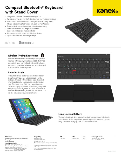
Compact Bluetooth® Keyboard with Stand CoverMPN UPC Color Packaging (W x H x L)K166-1053 814556019955 Black 135 mm X 20 mm X 283 mm 5.31 in. X 0.79 X 11.14 in.What’s Inside:Compact Bluetooth Keyboard with Stand CoverCharging Cable Quick Start GuideTechnical Specifications Keyboard Layout: Full QWERTY Layout Sync Connectivity: Four Bluetooth enabled devices Bluetooth Technology: Bluetooth 3.0Stand Cover Finish: Black faux-leather and soft microfiber inner lining Back of Keyboard: Stainless Steel finish Compatibility IOS: 7 and Above Android: 4.0 and Above Windows: XP / 7 / 8 / 10Bluetooth 3.0 supported smartphones and tablets *Compatible with Samsung, Motorola, Nexus and HTC Android smartphone.*Currently not compatible with LG, NOKIA, Sony smartphone Wireless Typing ExperienceThe keys are comfortable to use and just the right size for a take-with-you-anywhere keyboard. Bluetooth® 3.0 connectivity gives you the freedom to switch between your tablets, smartphones, laptops and other devices all from the comfort of one keyboard.Superior StylePremium black faux-leather and soft microfiber inner lining for a soft-touch and added protection for thekeyboard. The back of the keyboard is stainless steel which helps keep the keyboard cool and also looking great. The Stand Cover folds into a stand for a more convenient typing experience. Powerful magnets provideenough support for any tablet with up to 9” screen size. The keys are comfortable, durable, and responsive. All of this in a compact and low profile keyboard.Long Lasting BatteryThe internal battery is slim, lightweight, and with enough power to last up to 2-months on a single charge. When power is depleted, connect the keyboard using the included charging cable to a USB power source.•Designed to work with iPad ,iPhone and Apple TV •Full-size keys that give you the feel and comfort of a traditional keyboard •2-in-1: Stand Cover converts into a smartphone/tablet folding stand •Fits any tablet with up to 9” screen size, such as iPad Air series •Premium black faux-leather and soft microfiber inner lining •Removable keyboard with magnetic attachment •Syncs with your devices via Bluetooth 3.0•Also compatible with Android and Windows devices • Up to 2-month battery life on single charge。
旭子密码键盘测试方法

密码键盘测试工具XZ_F31_API_TEST.exe
1)启动测试工具XZ_F31_API_Test.exe
2)在【串口号】中选择相应的COM口->点击【打开串口】->选择【仿真键盘】,开始进
行明文输入测试
3)点击【打开键盘】,然后就可在密码键盘上输入,输入结果将显示在下面的文本输入框
中,测试完毕,点击【关闭键盘】结束明文输入测试。
点击【装载密钥】,进行密文输入测试。
4)装载主密钥,在【密钥下载模式选择】中选择【明文方式】->在【密钥属性】中选择【密
钥叠加】和【主密钥】->在【秘钥下载】中在【要下载的密钥号ID0】输入0,在【解密秘钥号ID1】中输入65535 ->点击【装载秘钥】->在最下方的静态框中显示装载秘钥成功与否。
接下来将装载工作秘钥
5)装载工作秘钥,在【密钥下载模式选择】中选择【正常模式】->在【密钥属性】中选择
【密钥叠加】和【PIN密钥】->在【秘钥下载】中在【要下载的密钥号ID0】输入1,在【解密秘钥号ID1】中输入0 ->点击【装载秘钥】->在最下方的静态框中显示装载秘钥成功与否。
到此秘钥装载完毕,点击【PIN操作】进行密文输入测试
6)在【PIN最大长度】选择6 -> 点击【输入PIN】->密码键盘上输入密码,当输入位数到
达6位后,将自动结束密码输入–> 输入的结果将在【PIN输入显示】中以“*”显示。
精品文档资料,适用于企业管理从业者,供大家参考,提高大家的办公效率。
精品文档资料,适用于企业管理从业者,供大家参考,提高大家的办公效率。
mlsobone密码锁说明书

mlsobone密码锁说明书MLSobone密码锁使用说明书一、引言欢迎使用MLSobone密码锁。
本说明书将详细介绍密码锁的安装、编程、使用及维护方法。
请在使用前仔细阅读本说明书,并按照说明进行操作,以确保密码锁的正常使用。
二、产品概述MLSobone密码锁是一款先进的电子密码锁,采用先进的技术和材料制造而成。
它具有多种开锁方式,包括密码解锁、指纹解锁、蓝牙解锁等。
本产品具有安全、方便、智能的特点,可以广泛应用于家庭、办公室、酒店等场所。
三、产品特点1. 多种开锁方式:支持密码解锁、指纹解锁、蓝牙解锁、机械钥匙解锁等多种方式。
2. 安全性高:密码采用虚拟密码技术,可以有效防止他人偷看密码。
指纹解锁采用高精度传感器,准确率高。
蓝牙解锁采用动态密码技术,提高了安全性。
3. 易于安装:本产品采用后盖式安装,无需拆卸门锁,只需安装在门内侧即可。
4. 易于操作:密码锁配备了大尺寸液晶显示屏和中英双语操作界面,操作简单直观。
5. 具备长续航能力:采用纳米电池技术,续航时间长,可满足长时间使用需求。
四、安全操作指南1. 请确保输入的密码正确并记住,在未来解锁时需要使用。
2. 指纹解锁时,请确保手指干净,不要有水、油等物质。
3. 不要将密码泄露给他人,以防密码被他人恶意使用。
4. 当遇到丢失指纹等异常情况时,请及时联系售后服务,避免安全问题。
五、安装步骤1. 在门内侧选择一个适合安装的位置,并使用转轴连接锁体和锁舌。
2. 将密码锁插入转轴上,并用螺丝固定,确保锁体牢固。
3. 将锁舌插入门框中的铰链框孔中,并用螺丝固定,确保锁舌能够正常伸缩。
4. 检查锁体、锁舌安装是否稳固,使用机械钥匙测试锁舌的伸缩是否正常。
六、使用方法1. 密码解锁:按下数字键盘上的数字键,输入正确的密码,然后按下“确认”键解锁。
2. 指纹解锁:将已注册的手指按压在指纹传感器上,直到指纹识别成功后解锁。
3. 蓝牙解锁:通过手机上的蓝牙连接MLSobone密码锁,并输入动态密码,即可解锁。
密码小键盘-深圳市智励电子有限公司文档

ZLE900系列密码小键盘使用说明书ZLE深圳市智励电子有限公司一、产品简介ZLE900系列密码键盘有15个长寿命按键,色彩高雅,外观漂亮。
通常作为计算机的外部设备,供输入交易代码、帐号及用户密码使用,广泛用于银行、邮政储蓄和证券交易的领域中,采用键盘仿真接口或串行通讯接口,可联接PC机或终端上使用。
二、技术参数:电源:DC+5V功耗:<200Mw重量:<200克按键:F1,F2,F3,0-9,“确认”,“清除”共15个按键三、型号说明:ZLE90口:接口为键盘口(用控制器来进行PC/终端键盘和密码键盘间的切换)ZLE90口K:接口为键盘口(没有控制器,用PC/终端键盘中的组合键来控制密码键盘的打开或关闭)ZLE90口S:接口为键盘口(没有控制器,用系统软件控制密码键盘的工作控制,常接终端的键盘铺口)ZLE90口R(D):接口为串口型,电平为RS232ZLE90口R(D):接口为串口型,电平为TTL注:串口型密码键盘除接口区别上,另有命令区别,详细需另见产品的软件版本号,型号中如有Z(D)表示该产品可增加DES加密法。
其中口包含意义如下:口 1 基本型2 语音提示3 液晶提示4 语音+液晶提示例:ZLE902K:为键盘方式接口,用PC键盘控制,语音提示。
四、联接示意图:1、ZLE90口密码键盘2、ZLE90口K密码键盘3、ZLE90口S 密码键盘4、ZLE90口R/ZLE90口RT 密码键盘连接PC 机或无+5V 电源输出的终端口五、键码:1、键盘口方式ZLE90口型/ZLE90口K 型/ZLE90口S 型密码键盘。
键位 定义0-9 数字0-9确定 同PC 键盘ENTER清除 同PC 键盘DEL2、串口通讯方式ZLE90口RT型密码键盘。
按键键值(ASCII字符)0 30H1 31H2 32H3 33H4 34H5 35H6 36H7 37H8 38H9 39H确认0DH清除08H注:依据用户的要求可以设定不同的键值。
EA2000用户手册v1.3

3.1 测温部件的校正 3.1.1 “测温部件”选项(使用校正电阻) 3.1.2 “测温部件”选项(使用标准电阻箱) 3.2 Pt100温度传感器校正 3.3 大气压力校正 3.4 校正日期
第四部分 故障报警及处理
第五部分 仪器的维护与保养
用户手册
1 2 4
5 5 7 10 14 18 20 21 21 21 22
注意事项
E A 2 0 0 0测 定 仪 在 设 计 、 制 造 和 检 测 过 程 中都有严格的质量保证,使用安全。但是,在 对该仪器进行操作时,有可能接触到腐蚀性的、 化学的或其他具有潜在危险的物质,如可燃的、 有毒的物料等等。使用该仪器对这些物质进行 操作时要特别小心。
请注意: 仔细阅读用户手册 穿好实验服 严格按照试验规程操作 做好安全工作,防止意外事故发生 严禁非专业人员对仪器进行拆装,谨防发生事故 禁止人为扳动或碰撞点火臂、传感器臂、灭 火盖子等机械部分,要想操作这些部分,请 进入试验程序按指令按钮进行操作,如果非 正常断电导致该机械部分不在复位位置,请 等 待2 0 S后 重 新 上 电 , 该 部 位 可 以 自 动 复 位 。
EA 2000
用户手册
1、 点 燃 火 焰 存 在 传 感 器 4、 灭 火 盖 子 7、 电 子 点 火 器 接 口 1 0、 P t1 00温 度 传 感 器
图1 - 3
2、 熔 断 丝
3、 点 火 臂
5、 Pt 1 00温 度 传 感 器 接 口 6、 闪 点 燃 点 传 感 器 接 口
8、 点 燃 试 验 火 焰
1套
9. 水 银 温度 计 (高、 低 温各1支)
2支
10. 鼠标
1个
11. 标准小键盘
- 1、下载文档前请自行甄别文档内容的完整性,平台不提供额外的编辑、内容补充、找答案等附加服务。
- 2、"仅部分预览"的文档,不可在线预览部分如存在完整性等问题,可反馈申请退款(可完整预览的文档不适用该条件!)。
- 3、如文档侵犯您的权益,请联系客服反馈,我们会尽快为您处理(人工客服工作时间:9:00-18:30)。
密码小键盘安装手册及测试说明
V1.3
一、安装部分
说明:
此密码小键盘整个套装包含两部分,一部分是输入键盘,另一部分是串口扩展盒设备。
密码键盘不能单独直接接PC电脑,必须连接串口扩展盒才能与电脑连接。
1.将串口扩展盒串口1与U口分别连接在电脑的串口和U口上。
2.串口扩展盒每个接口旁都有不同的英文加以区分,分为A、B、C、K,
将密码键盘的串口线(串口2)接在扩展盒的K口上。
3.设备正常连接的话,正常供电后,密码键盘会发出“嘟“的提示声音,
并且扩展盒设备警示灯为绿色。
(当使用到密码键盘功能时会有提示音
“请输入密码”)。
各接口如下图1:
图1
二、测试部分
(一)测试方式一
1、将测试软件“BP04Test.exe”拷贝进电脑。
2、双击“BP04Test.exe”图标,出现如下画面:
①设置连接端口为“COM1”
②设置扩展口“K”口
③点击“南天包方式输入密码”
④设备正常连接的话,密码键盘会有提示音“请输入密码”
⑤输入任意一组(不大于十个数字长度)数字后,按密码键盘上的确认键
⑥软件界面会出现之前所输入的数字信息。
⑦按PC键盘上的ESC键停止测试,点击“退出”框退出。