moog J079伺服阀
伺服阀调零
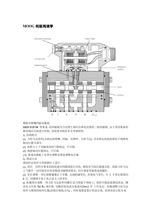
MOOG伺服阀调零穆格双喷嘴挡板伺服阀MOO G D769 型来说,该伺服阀为力反馈2阀芯位移电反馈的二级伺服阀, 由于采用集成电路对阀芯位移进行控制, 因而使该阀具有无零漂特性。
1) 结构特点(1) 力矩马达组件(含固定的喷嘴、挡板、反馈杆、力矩马达) 及其固定的底座相对于阀体的轴向位置可调节。
(2) 衔铁与上下导磁体间的气隙固定, 不可调。
(3) 阀套轴向位置固定, 不可调。
( 4) 集成电路板上有零位调整及增益调整电位器。
2) 调试方法调试时必须在专用检测台上进行。
(1) 清洁用符合要求的清洗液对伺服阀进行冲洗, 确保各节流孔畅通无阻。
清除力矩马达上气隙中一切可能存在的异物或导磁物质粉末, 均匀预紧导磁体连接螺钉。
(2) 零位调整零位调整遵循以下步骤, 先调机械零位, 再调电气零位, 当2 个零位都调为0 后, 伺服阀才处于真正意义上的零位。
a) 机械零位调整将力矩马达组件用螺钉适当预紧于阀体上, 保持空载流量测试状态, 测试压力升到7M Pa 阀压降, 切断控制电流及集成电路±15 V 工作电压。
轻微调整力矩马达组件与阀体的相对位置(沿阀芯轴线方向) , 同时观察流量计的显示值, 直到该显示值为0。
此时说明阀芯与阀套间的轴向位置已正确, 阀芯两端压差为0, 阀无液压信号输出, 机械零位已调好。
b) 电气零位调整保持空载流量测试状态, 切断控制电流, 接通集成电路±15 V 工作电源。
调节调零电位器直到流量计输出显示为0, 此时电气零位已调好。
(3) 测试伺服阀零位调好后, 对该阀的空载流量、压力增益、内泄漏、阀芯位移反馈电压曲线进行测试, 通过曲线可以精确地判断出该阀静态特性指标的好坏。
3) 小结以上调试方法均是建立在喷嘴轴向位置未遭到破坏, 力矩马达的4 个气隙的几何位置均正确的情况下进行的。
若喷嘴已偏离正确位置, 则需通过专用工具调整喷嘴轴向位置。
若衔铁不处于气隙中间位置, 则可通过更换厚度不同的导磁体垫片进行调整。
电液伺服阀维护和修理保养 伺服阀维护和修理保养
电液伺服阀维护和修理保养伺服阀维护和修理保养MOOG电液伺服阀维护和修理保养从事ATOS比例阀维护和修理,REXROTH比例阀维护和修理,MOOG伺服阀维护和修理,PARKER柱塞泵维护和修理,电液传动掌控行业资深服务维护和修理专家主营产品:一、液压泵:柱塞泵、齿轮泵、中低压变量叶片泵、中低压定量叶片泵二、压力阀:溢流阀、减压阀、次序阀、背压阀、卸荷阀三、方向阀:电磁换向阀、电液换向阀、手动换向阀、单向阀、液控单向阀、充液阀四、流量阀:节流阀、电磁流量阀、调速阀、电磁调速阀、机械节流阀、机床专用阀五、叠加阀:溢流阀、减压阀、电控减压阀、抗衡阀、先导式抗衡阀、电磁流量阀、单向节流阀、节流阀、单向阀、缓冲阀六、液压电机:液压电机、电机泵组七、比例阀:电液比例先导溢流阀、电液比例溢流阀、电液比例溢流调速阀八、插装阀:逻辑阀、埋入式溢流阀、先导式抗衡泄载阀、单向阀管路冲洗时,不应装上伺服阀,可在安装伺服阀的安装座上装一冲洗板。
假如系统本身允许的话,也可装一换向阀,这样工作管路和执行元件可被同时清洗。
向油箱内注入清洗油(清洗油选低粘度的专用清洗油或同牌号的液压油),启动液压源,运转冲洗(系统各元件都能动作,以便清洗其中的污染物)。
在冲洗工作中应轻轻敲击管子,特别是焊口和连接部位,这样能起到除去水锈和尘埃的效果。
同时要定时检查过滤器,如发生堵塞,应适时更换滤芯,更换下来的纸滤芯、化纤滤芯、粉末冶金滤芯不得清洗后再用,其他材质的滤芯视情况而定。
更换完毕后,再连续冲洗,直到油液污染度符合要求,或看不到滤油器滤芯污染为止。
排出清洗油,清洗油箱(建议用面粉团或胶泥粘去固定颗粒,不得用棉、麻、化纤织品擦洗),更换或清洗滤油器,再通过5~10m的滤油器向油箱注入新油。
启动油源,再冲洗24小时,然后更换或清洗滤器,完成管路清洗。
1.2在伺服阀进油口前必需配置公称过滤精度不低于10m?的滤油器,而且是全流通的非旁路型滤油器。
MOOG伺服阀及其各种伺服阀型号概要

供应MOOG穆格伺服阀D691-072D/Q08FBAABNVS0N型号:其中MOOG是为伺服阀,而D691-072D是直动式伺服阀的型号。
以下是各种伺服阀及其动能作用,希望对你有帮助。
Moog伺服阀 G631-3002BMoog伺服阀 G631-3004BMoog伺服阀 G631-3006BMoog伺服阀 G761-3003-5Moog伺服阀 G761-3009AMoog伺服阀 G761-3602Moog伺服阀 G761-3605Moog伺服阀 G040-123-001Moog伺服阀 D792-5002Moog伺服阀 D791-5045Moog伺服阀 D791-5021Moog伺服阀 D791-5008Moog伺服阀 D765-1603-5Moog伺服阀 D765-1048-5Moog伺服阀 D664Z4382KMoog伺服阀 D664Z4306KMoog伺服阀 D664-4714Moog伺服阀 D664-4384KMoog伺服阀 D664-4383KMoog伺服阀 D664-4311KMoog伺服阀 D664-4013Moog伺服阀 D664-4009Moog伺服阀 D663Z4322KMoog伺服阀 D663Z4307KMoog伺服阀 D663Z4305KMoog伺服阀 D663-5002Moog伺服阀 D663-4769Moog伺服阀 D663-4705Moog伺服阀 D663-4025Moog伺服阀 D663-4318KMoog伺服阀 D663-4007Moog伺服阀 D663-4012Moog伺服阀 D663-306K Moog伺服阀 D663-1922E-4 Moog伺服阀 D662Z4815 Moog伺服阀 D662Z4814 Moog伺服阀 D662Z4813 Moog伺服阀 G761-3009A Moog伺服阀 D662Z4336K Moog伺服阀 G761-3605 Moog伺服阀 D662Z4380 Moog伺服阀 D662Z4384K Moog伺服阀 D662Z4341K Moog伺服阀 M040-104B Moog伺服阀 G040-123-001 Moog伺服阀 D662-4038 Moog伺服阀 D661-4652 Moog伺服阀 D661-4313C Moog伺服阀 D661-4332C Moog伺服阀 D661-4334C Moog伺服阀 D661-4438E Moog伺服阀 D661-4451C Moog伺服阀 D661-4507C Moog伺服阀 D661-4575C Moog伺服阀 D661-4576C Moog伺服阀 D661-4586E Moog伺服阀 D661-4594C Moog伺服阀 D661-4624 Moog伺服阀 D661-4636 Moog伺服阀 D661-4640 Moog伺服阀 D661-4649 Moog伺服阀 D661-4650 Moog伺服阀 D661-4651 Moog伺服阀 D661-4652 Moog伺服阀 D661-4691C Moog伺服阀 D661-4697CMoog伺服阀 D661-4773 Moog伺服阀 D661-4776 Moog伺服阀 D661-4782 Moog伺服阀 D661-4790 Moog伺服阀 D661-4826 Moog伺服阀 D661-4867 Moog伺服阀 D661-5611 Moog伺服阀 D661-5625C Moog伺服阀 D662-1923E-4 Moog伺服阀 D662-4010 Moog伺服阀 D662-4014 Moog伺服阀 D662-4036 Moog伺服阀 D662-4037 Moog伺服阀 D662-4038 Moog伺服阀 D662-4065 Moog伺服阀 D662-4083 Moog伺服阀 D662-4099 Moog伺服阀 D662-4723 Moog伺服阀 D662-4846 Moog伺服阀 D662-4884 Moog伺服阀 D662Z1931E Moog伺服阀 D662Z4017 Moog伺服阀 D662Z4336K Moog伺服阀 D662Z4341K Moog伺服阀 D662Z4378K Moog伺服阀 D662Z4380 Moog伺服阀 D662Z4384K Moog伺服阀 D662Z4813 Moog伺服阀 D662Z4814 Moog伺服阀 D662Z4815 Moog伺服阀 D663-1922E-4 Moog伺服阀 D663-306K Moog伺服阀 D663-344K Moog伺服阀 D663-4007Moog伺服阀 D663-4025 Moog伺服阀 D663-4318K Moog伺服阀 D663-4705 Moog伺服阀 D663-4769 Moog伺服阀 D663-5002 Moog伺服阀 D663-5304K Moog伺服阀 D663Z4305K Moog伺服阀 D663Z4307K Moog伺服阀 D663Z4322K Moog伺服阀 D664-4009 Moog伺服阀 D664-4013 Moog伺服阀 D664-4311K Moog伺服阀 D664-4383K Moog伺服阀 D664-4384K Moog伺服阀 D664-4714 Moog伺服阀 D664Z4306K Moog伺服阀 D664Z4382K Moog伺服阀 D765-019-5 Moog伺服阀 D765-1048-5 Moog伺服阀 D765-1603-5 Moog伺服阀 D791-5008 Moog伺服阀 D791-5045 Moog伺服阀 D791-5021 Moog伺服阀 D792-5002 Moog伺服阀 G040-123-001 D661-4651D661-4652D661-4636D661-4469CD661-4697CD661-4033D661-4059D661-4444CD661-4443CD661-4506CD661-4539CD662Z4311KD662-4010D662Z4336KD663Z4307KD663-4007D663Z4307KD663-4007D634-341CD634-319CD633-333BD791-5009D791-4025D791-4001D791-4002D791-4028D791-4046072-559AD633-312BD633-442BD633-526BD633-419BD633-473BD633-500BD633-314AD633-333BD633-442BD633D633-D2500BD633-D2501BD633-362B/穆格滤芯A67999-065 穆格滤芯A67999-100 穆格滤芯A67999-200穆格滤芯A88594-004 B46634-002B46744-004B61042-005B67728-001B96839-001B97007-061B97027-012B97036-001B97067-111B97069-061C70935-001D631-502FD631-F550FD633-183BD633-303BD633-308BD633-313BD633-315BD633-317BD633-333BD633-380BD633-460BD633-471BD633-472BD633-473BD633-481BD633-495BD633-Z371BD633-501BD633-525BD633D2504BD633-599BD633-603BD634-1035D634-1063D634-400CD634-501AD634-538AD634-543AD634K2000C D635-671ED635-Z681E D691-069DD691-072D-7 D636-225-0000 D661-4003D661-393DD661-4009D661-4023D661-4059D661-4051D661-4055D661-4033D661-4069D661-4070D661-4099D661-4157BD661-4158BD661-4168D661-4178D661-4186D661-4187D661-6405CD661-4303ED661-4313CD661-4332CD661-4334CD661-4341CD661-4438E D661-4443C D661-4444C D661-4451C D661-4506C D661-4507C D661-4575C D661-4576C D661-4577C D661-4586E D661-4594C D661-4624 D661-4636 D661-4640 D661-4649 D661-4650 D661-4651 D661-4652 D661-4688C D661-4691C D661-4697C D661-4729 D661-4773 D661-4776 D661-4782 D661-4790 D661-4826 D661-4867 D661-4931 D661-5611 D661-5625C D661-6313C D661-6324 D661-6326D661-6359D661-6347CD661-6393CD661-6397CD661-6360D661-6372ED661-6428ED662-1923E-4D662-4005 D01HABF6VSX2 D662-4032D662-4010D662-4013D662-4014D662-4036D662-4037D662-4038D662-4050D662-4065D662-4087D662-4083D662-4099D662-4106BD662-4115D662-4118BD662-4124D662-4723D662-4846D662-4884D662-4930D662Z1931ED662Z4017D662Z4310KD662Z4334D662Z4336KD662Z4341K D662-Z4372A D662Z4378K D662Z4380D662Z4384K D662Z4615K D662Z4813D662Z4814D662Z4815D663-1922E-4 D663-306KD663-344KD663-4002D663-4006D663-4007D663-4012D663-4025D663-4031D663-4317D663-4318K D663-4705D663-4769D663-5002D663-5304K D663Z4305K D663Z4307K D663Z4322K D664-4009D664-4013D664-4036D664-4039D664-4311K D664-4383K D664-4384KD664-4714D664-4784D664Z4306KD664Z4382KD664Z4406KD671-0039-0001 D671-0040-0001 D671-0051-0001 D671-0052-0001 D671-0068-0001 D671-0070-0001 D672-0006-0000 D672-0013-0001 D672-0026-0001 D672-0027-0001 D672-0028-0001 D672-0036-0001 D672-0037-0001 D672-5706-0001 D673-0001-0000 D673-5702-0001 D673-5705-0001 D674-0015-0001 D674-5706-0001 D675-5704-0001 D675-5705-0001 D682Z4059D682Z4060D683-4822D683Z4010D684-4912D684Z4011D685-4837DD685-4868D765-019-5D765-1048-5D765-1603-4D765-1603-5D791-5008D791-5021D791-5045D792-4013/S99JOQA6VSX2-B D792-5002D792-5018G040-123-001G631-3002BG631-3004BG631-3005BG631-3006BG631-3008BD636-312-0001D636-313-0001D683-4834G761-3033BG761-3003B5G761-3005BG761-3004B5G761-3009BG761-3602BG761-3605BM040-104BD951-2025-10D951-2007-10D951-2009-10D951-2079-10D952-2001-10D952-2007-10D952-2009-10D953-2001-10D953-2015-10D953-2017-10D954-2003-10D954-2011-10D954-2013-10D955-2003-10D955-2013-10D955-2017-10D956-2003-10D956-2015-10D956-2011-10D956-2017-10D957-2003-10J761-003J761-004G122-824-002072-560AD691-069DD635-671ED691-072DD062-512F760F911A-HP5?S10K0GM4VPL D633-632D663-339NC072-560A,替代型号072-1203-9 D635-671ED061-9321D061-823C072-1202-100514 RKP 柱塞泵G631-3705BD662-3303K P01HLMF6NEC2-0 D638-206-0001D638-216-0001G122-202A001L129-034-A007(S/N)L103G122-829-001G122-829-001G123-825-001G761-3001BD684-4915G631-3800BG771K202 S19FOFA4VA4G771K200 S19FOFA4UI4G771K208 S02FOFA4VA4G771K200 H19FOFA4VI4G771K202 H19FOFA4V24G771K208 H02FOFA4V24G772K240 S38FOFA4V14D691-078D-6D953-2017/c HP-RKP045KM28111Z200D952-2001-10 HPR18A1 RKP032KM28J1Z00D952-2007-10 HPR18A1 RKP032KM28F2Z00D955-2017-10 HPR18A1 RKP080KM28J1Z00D955-2003-10 HPR18A1 RKP080KM28F2Z00D634直动式伺服阀MOOG D634,直动阀(DDV)是具有内部阀芯位置电反馈的伺服阀。
Moog Inc. Series 72K 电液伺服阀手册说明书
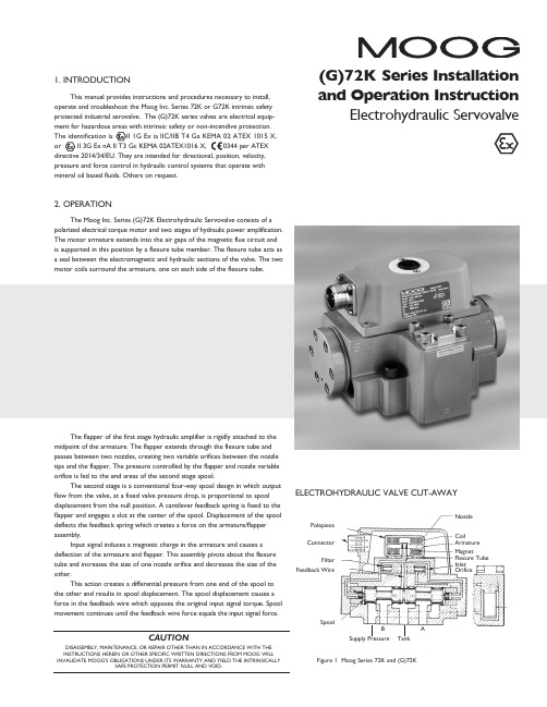
�(G)72K Series Installation ELECTROHYDRAULIC VALVE CUT-AWAYCoilArmature MagnetFlexure Tube Inlet OrificePolepiece ConnectorFilterFeedback WireSpoolFigure 1 Moog Series 72K and (G)72KSupply PressureBTankANozzle3. ELECTRICAL INFORMATION AND INTRINSICALLY SAFE CIRCUIT SAFETY PARAMETERSa. A wide choice of coils is available for a variety of rated currentrequirements. The torque motor coil leads are attached to the connector so external connections can provide series, parallel or single coiloperation. The valves are equipped either with an MS type connector or with pigtail leads for electrical wiring. Refer to installation drawings of the specific model for details. Servovalve coils should be driven with current to provide consistency throughout the temperature range.b. The (G)72K valves are approved for intrinsically safe protection per EN60079-11. The approved safety parameters are listed in the following table for all the coils used by (G)72K series. Coil number is marked on thevalve nameplate.Coil Configuration Marking U i (MAX) I i (MAX) G4220-031 (single, series, parallel) Ex ia IIB T4 12 V 120 mAG4220-051/098 (single, series, parallel) Ex ia IIB T4 12 V 240 mAG4221-001 G4220-042 (single) Ex ia IIC T4 16 V 160 mA G4221-001 G4220-042 (single) Ex ia IIC T4 24.4 V 85 mAG4220-031 (single, parallel) Ex ia IIC T4 30 V 26 mAG4220-031 (series) Ex ia IIC T4 30 V 18 mAG4220-051/098 (single, parallel) Ex ia IIC T4 30 V 19 mA G4220-051/098 (series) Ex ia IIC T4 30 V 12.7 mAG4220-042 (single) Ex ia IIC T4 30 V 37 mAG4220-042 (parallel) Ex ia IIC T4 30 V 20 mAG4220-042 (series) Ex ia IIC T4 30 V 10 mAG4221-001 (single) Ex ia IIC T4 30 V 28 mAc. The (G)72K valves are approved for non-incendive operation for supplycurrent not to exceed 50 mA dc.d. When making electric connections to the valve, appropriate measures mustbe taken to ensure that locally different earth potential do not result inexcessive ground currents. When barriers are required for the hazardous location, hazardous area (field) wiring must meet the requirements ofthe barrier manufacturer. All barriers must be mounted and installed incompliance with the barrier manufacturer’s requirements. Twisted pairs of 18-20 gage wire are recommended. If shielded wire is used, connect shield wire to earth ground only at the barrier strip.4. SPECIAL CONDITIONS FOR SAFE USEBecause the enclosure of the apparatus is made of aluminum, if it is mounted in an area where the use of category 1 G apparatus is required, it must be installed such that even in the event of rare incidents, ignition sources due to impact and friction sparks are excluded.When the electrohydraulic servovalve is used in an application for type of explosion protection intrinsic safety “i”, the appropriate box on the data label must be scored. When the electrohydraulic servovalve is used in an application for type of explosion protection “n”, the appropriate box on the data label must be scored.After use in an application for type of explosion protection “n”, the servovalve cannot abe safely used in a intrinsically safe application.The screwed cable connector may only be disconnected when the circuit is de-energized or when the location is known to be non-hazardous.When used at an ambient temperature ≥70°C, heat resistant cable must be used with a continuous operating temperature in accordance with the application.5. HYDRAULIC SYSTEM PREPARATIONTo prolong servovalve operational life and to reduce hydraulic system maintenance, it is recommended that the hydraulic fluid be kept at a cleanliness level of ISO DIS 4406 Code 16/13 maximum, 14/11 recommended. The most effective filtration scheme incorporates the use of a kidney loop or “off-line” filtration as one of the major filtration components. The filter for the “off-line” filtration scheme should be a ß3≥75 filter for maximum effectiveness.Upon system startup and prior to mounting the servovalve, the entire hydraulic system should be purged of built-in contaminating particles by an adequate flushing. The servovalve should be replaced by a flushing manifold and the hydraulic circuit powered up under conditions of fluid temperature and fluid velocity reasonably simulating normal operating conditions. New system filters are installed during the flushing process whenever the pressure drop across the filter element becomes excessive. The flushing processes should turn over the fluid in the reservoir between fifty to one hundred times.To maintain a clean hydraulic system, the filters must be replaced ona periodic basis. It is best to monitor the pressure drop across the filter assembly and replace the filter element when the pressure drop becomes excessive. In addition to other filters that are installed in the hydraulic circuit, it is recommended that a large capacity, low pressure ß3≥75 filter be installedin the return line. This filter will increase the interval between filter element replacements and greatly reduce the system contamination level.6. INSTALLATIONThe Moog (G)72K series industrial servovalve may be mounted in any position, provided the servovalve pressure, control, and tank ports match respective manifold ports. The mounting pattern and port location of the servovalve is shown on Figure 4. The servovalve should be mounted with 3/8-16 x 2.00 inch long, socket head cap screws. Apply a light film of oil to the screw threads and torque to 175 inch-pounds. Wire mating connector for desired coil configuration and polarity. Thread connector to valve.7. MECHANICAL NULL ADJUSTMENTIt is often desirable to adjust the flow null of a servovalve independent of other system parameters. The “mechanical null adjustment” on the Moog (G)72K Series servovalve allows at least ±20% adjustment of flow null. The “mechanical null adjustor” is an eccentric bushing retainer pin, located above the tank port designation on the valve body (see Figure 2) which, when rotated, provides control of the bushing position. Mechanical feedback elements position the spool relative to the valve body for a given input signal. Therefore, a movement of the bushing relative to the body changes the flow null. Mechanical Adjustment ProcedureUsing a 3/8 inch offset box wrench, loosen the self-locking fitting until thenull adjustor pin can be rotated. (This should usually be less than 1/2 turn). DO NOT remove self-locking fitting. Insert a 3/32 inch Allen wrench in null adjustor pin. Use the 3/32 Allen wrench to rotate the mechanical null adjustor pin to obtain desired flow null. Torque self-locking fitting to 57 inch lbs. Note:Clockwise rotation of null adjustor pin produces flow from port P to port B.Tools and Equipmenta. Blade screwdriverb. Allen wrench set (3/32, 7/64, 3/8, 3/16)c. No. 2-56 NC by 11/2 inch screwd. Torque wrenchese.3/8 inch offset box wrenchf. TweezersFigure 2Mechanical NullAdjustment10. FIELD REPLACEABLE FILTER ASSEMBLY REPLACEMENTa.Remove four socket head cap screws and lockwashers on filter cover using a 3/16 inch Allen wrench. Remove filter cover plate. Use to pull filter plug out.b. Remove o-rings and old filter from filter plug.c. Inspect filter for foreign material and discard.d. Install o-rings on filter plug and inside new filter.e.Install filter, filter plug and cover plate. Torque screws to 85 inch-pounds.11. FUNCTIONAL CHECKOUT AND CENTERINGa. Install servovalve on hydraulic system or test fixture, but do not connect electrical lead.b. Apply required system pressure to servovalve and visually examine for evidence of external leakage. If leakage is present and cannot be rectified by replacing o-rings, remove the discrepant component and return for repair or replacement.Note: If the system components are drifting or hardover, adjust the mechanical null of the servovalve.c. Connect electrical lead to servovalve and check phasing in accordancewith system requirements.Figure 3Filter Tube Inlet Orifice AssemblyFilter PlugFieldReplaceable FilterFilter HousingO-Rings8. GENERAL SERVICING RECOMMENDATIONSa. Disconnect electrical lead to servovalve.b. Relieve hydraulic system of residual pressure.(G)72K SERIES INSTALLATION AND OPERATION INSTRUCTIONCDS6754 RevD 500-448 0718Moog Inc., East Aurora, NY 14052-0018 Telephone: 716/652-2000Fax: 716/687-7910Toll Free: 1-800-272-MOOG TYPICAL WIRING SCHEMATICThe products described herein are subject to change at any time without notice, including, but not limited to, product features, specifications, and designs.3。
moog伺服阀中文样本
moog伺服阀中文样本近年来,工业领域的电气设备飞速发展,各种高性能控制器、传感器、电机等被广泛应用于机械、航空、轨道交通、化工等领域。
而在这些设备中,伺服阀作为一种高性能调节元件,具有很强的动态响应能力和精准的流量调节能力,在国内外市场上也备受青睐。
而本文就是主要介绍moog伺服阀中文样本。
1. moog伺服阀是什么?moog伺服阀是一种高精度的电子液压控制阀门,可以通过电信号控制流体通路的开闭,从而实现对液压系统的精准控制。
moog伺服阀结构简单、性能稳定、响应速度快,广泛应用于工业、机械、冶金、航空、轨道交通等领域。
2. moog伺服阀的特点(1)高精度:moog伺服阀可以在高达1毫秒的时间窗口内完成对系统的反馈、控制和补偿,具有极高的控制准确性。
(2)高速度:moog伺服阀响应速度快,同样可以在1毫秒的时间内完成控制操作,适用于高速液压系统的控制。
(3)多功能:moog伺服阀具有多种控制方式和控制策略,可以满足不同应用场合的需求。
(4)质量稳定:moog伺服阀的设计采用了成熟的理论和技术,采用高品质材料和先进工艺制造,保证了产品的质量稳定和寿命长。
(5)适应性强:moog伺服阀具有良好的环境适应性和抗干扰性能,适合各种恶劣工作环境。
3. moog伺服阀的应用moog伺服阀被广泛应用于各种液压控制系统中,如工业、机械、冶金、航空、轨道交通等领域。
其中主要应用于液压伺服系统,如机床、注塑机、液压动力头、液压马达等该领域。
同时,moog伺服阀也被应用于一些特殊领域,如航空航天、核工业、海洋工程等。
4. moog伺服阀的选型moog伺服阀的选型需要考虑多个因素,如液压系统的工作压力、精度要求、流量要求等,同时也需要考虑系统的工作环境和可靠性要求等。
在选型时,可以参考moog伺服阀中文样本和其它资料进行比较和评估,选择最适合自身需求的产品。
5. 结论Moog伺服阀是一种具有高精度、高速度、多功能、适应性强等特点的液压控制阀门,广泛应用于各种液压系统中。
MOOG穆格伺服阀的特点_5
MOOG穆格伺服阀的特点MOOG伺服阀通常应用于精密场合的精密控制设备,而比例阀主要用于满足基本控制应用的需求。
伺服阀和比例阀的主要区别在于中位遮盖量的不同。
伺服阀阀芯遮盖量小于行程的3%,而比例阀遮盖量为大于或等于3%(参考ISO 5598)。
因而,通常伺服阀阀芯在经过硬化的阀套内移动,而比例阀的阀芯直接在铸铁阀体内移动(MOOG的比例阀也具有阀套)。
所有的MOOG伺服阀和比例阀都装有阀芯位置闭环控制装置,因此需要一个阀芯位置反馈。
MOOG采用两种反馈:机械反馈和电气反馈。
机械反馈(MFB)阀利用一根反馈弹簧杆,当阀芯运动使其受力变形时,给出一个机械反馈信号至力矩马达。
这类阀不需要集成电子放大器来操作。
电气反馈(EFB)阀利用电气位置传感器检测阀芯位置。
由于信号电气反馈,EFB阀需要集成的电子放大器来操作。
MOOG阀通常把放大器集成于阀体,无需外置的控制放大器D662-4010_D662-1923E-4_MOOG伺服阀特征阀芯阀套设计(BSA)阀芯遮盖量< ±1%很高的压力增益很高的精度和动态特性额定流量基于压降70bar2 MOOG比例阀特征阀芯阀体设计(SiB)阀芯遮盖量≥3%比伺服阀略低的精度和动态特性比伺服阀高的额定流量额定流量基于压降10bar133技术62858122MOOG伺服阀D633、D634系列伺服阀是MOOG公司对其经久考验,盛名于世的双喷嘴力反馈两级伺服阀的发展与补充,区别在于D633、D634系列伺服阀从结构上取消了喷嘴一挡板前置级、用大功率的直线力马达替代了小功率的力矩马达,用先进的集成块与微型位置传感器替代了工艺复杂的机械反馈装置—力反馈杆与弹簧管,从而简化了结构,提高了可靠性,大大地降低了制造成本,却保持了带喷挡前置级的两级伺服阀的基本性能与技术指标。
DDV伺服阀D633、D634系列伺服阀是MOOG公司对其经久考验,盛名于世的双喷嘴力反馈两级伺服阀的发展与补充MOOG DDV伺服阀的特点1.在位置、速度、压力以及力电液伺服系统中可用二位二通、三位三通或三位四通的方式进行工作。
美国MOOG伺服阀-伺服阀的工作原理及作用
美国MOOG伺服阀,伺服阀的工作原理及作用1、电液伺服阀主要用于电液伺服自动控制系统,其作用是将小功率的电信号转换为大功率的液压输出,经过液压执行机构来完成机械设备的自动化控制.伺服阀是一种经过改动输入信号。
依据输入信号的方式不同,分为电液伺服阀和机液伺服阀。
电液伺服阀既是电液转换元件,又是功率放大元件,它的作用是将小功率的电信号输入转换为大功率的液压能(压力和流量)输出,完成执行元件的位移、速度、加速度及力控制。
液压泵的输出压力是指液压泵在实践工作时输出油液的压力,即泵工作时的出口压力,通常称为工作压力,其大小取决于负载。
电液伺服阀通常由电气—机械转换安装、液压放大器和反应(均衡)机构三局部组成。
反应战争衡机构使电液伺服阀输出的流量或压力取得与输入电信号成比例的特性。
压力的稳定通常采用压力控制阀,比方溢流阀等。
2.细致材料:典型电---气比例阀、伺服阀的工作原理电---气比例阀和伺服阀按其功用可分为压力式和流量式两种。
压力式比例/伺服阀将输给的电信号线性地转换为气体压力;流量式比例/伺服阀将输给的电信号转换为气体流量。
美国威格士VICKERS柱塞泵由于气体的可紧缩性,使气缸或气马达等执行元件的运动速度不只取决于气体流量。
还取决于执行元件的负载大小。
因而准确地控制气体流量常常是不用要的。
单纯的压力式或流量式比例/伺服阀应用不多,常常是压力和流量分离在一同应用更为普遍。
电---气比例阀和伺服阀主要由电---机械转换器和气动放大器组成。
但随着近年来低价的电子集成电路和各种检测器件的大量呈现,在1电---气比例/伺服阀中越来越多地采用了电反应办法,这也大大进步了比例/伺服阀的性能。
电---气比例/伺服阀可采用的反应控制方式,阀内就增加了位移或压力检测器件,有的还集成有控制放大器。
滑阀式电---气方向比例阀美国穆格伺服阀,流量式四通或五通比例控制阀能够控制气动执行元件在两个方向上的运动速度,这类阀也称方向比例阀。
MOOG伺服阀结构及工作原理

MOOG伺服阀结构及工作原理MOOG伺服阀是电液转换元件,它能把微小的电气信号转换成大功率的液压输出。
其性能的优劣对电液调节系统的影响很大,因此,它是电液调节系统的核心和关键。
为了能够正确使用电液调节系统,必须了解MOOG伺服阀的工作原理。
1MOOG伺服阀的分类1)按液压放大级数可分为单级MOOG伺服阀,两级MOOG伺服阀,三级MOOG伺服阀。
2)按液压前置级的结构形式,可分为单喷嘴挡板式,双喷嘴挡板式,滑阀式,射流管式和偏转板射流式。
3)按反馈形式可分为位置反馈式,负载压力反馈式,负载流量反馈式,电反馈式。
4)按电机械转换装置可分为动铁式和动圈式。
5)按输出量形式分为流量伺服阀和压力控制伺服阀。
2MOOG伺服阀结构及工作原理(以双喷嘴挡板为例)双喷嘴挡板式力反馈二级MOOG伺服阀由电磁和液压两部分组成。
电磁部分是永磁式力矩马达,由永久磁铁,导磁体,衔铁,控制线圈和弹簧管组成。
液压部分是结构对称的二级液压放大器,前置级是双喷嘴挡板阀,功率级是四通滑阀。
画法通过反馈杆与衔铁挡板组件相连。
力矩马达把输入的电信号(电流)转换为力矩输出。
无信号时,衔铁有弹簧管支撑在上下导磁体的中间位置,永久磁铁在四个气隙中产生的极化磁通是相同的力矩马达无力矩输出。
此时,挡板处于两个喷嘴的中间位置,喷嘴两侧的压力相等,滑阀处于中间位置,阀无液压输出;若有信号时控制线圈产生磁通,其大小和方向由信号电流决定,磁铁两极所受的力不一样,于是,在磁铁上产生磁转矩(如逆时针),使衔铁绕弹簧管中心逆时针方向偏转,使挡板向右偏移,喷嘴挡板的右侧间隙减小而左侧间隙增大,则右侧压力大于左侧压力,从而推动滑阀左移。
同时,使反馈杆产生弹性形变,对衔铁挡板组件产生一个顺时针方向的反转矩。
当作用在衔铁挡板组件上的电磁转矩、弹簧管反转矩反馈杆反转矩等诸力矩达到平衡时,滑阀停止移动,取得一个平衡位置,并有相应的流量输出。
滑阀位移,挡板位移,力矩马达输出力矩都与输出的电信号(电流)成比例变化。
- 1、下载文档前请自行甄别文档内容的完整性,平台不提供额外的编辑、内容补充、找答案等附加服务。
- 2、"仅部分预览"的文档,不可在线预览部分如存在完整性等问题,可反馈申请退款(可完整预览的文档不适用该条件!)。
- 3、如文档侵犯您的权益,请联系客服反馈,我们会尽快为您处理(人工客服工作时间:9:00-18:30)。
J079-100 and J079-200 Series3-Stage Servovalves with Integrated ElectronicsThe J079-100 and J079-200 Series are throttle valves for 3-way and 4-way applications. They have been developed specifically for demandingapplications requiring both high flow rates and high response. The internal amplifier is designed for high reliability, using SMD technology for concussion resistance. The valves are offered with 730 or 761 2-stage pilot valves. Electrical feedback J769 and J739 Series are available for longer life and higher response. The valves are also available in standard (21MPa) and high (35MPa) pressure versions. The J079-100 Series can deliver rated flow of 114 or 228 l/min and the J079-200 up to 757 l/min. These valves are suitable for pressure or force control, position, and speed control on high response systems.Principle of operationAn electrical command signal is applied to the integrated control amplifier which drives a current through the pilot valve coils. The pilot valve produces differential pressure in its control ports. This pressure difference results in pilot flow which causes main spool displacement.The position transducer which is excited via an oscillator measures the position of the main spool. This signal is then demodulated and fed back to the control amplifier where it is compared with the command signal. The control amplifier drives the pilot valve until the error between command signal and feedback signal is zero. Thus, the positionof the main spool is proportional to the electrical command signal.Operational features■Electrical position feedback with pressure isolated position transducer, eliminates wear■Integrated SMD electronics with false polarity protection■Optional external pilot supply and return connections via fifth and sixth port in valve body■Low hysteresis and threshold, and excellent null stability■Pre-adjusted at the factoryThe actual flow depends on the electrical command signal and the valve pressure drop, and may be calculated using the square root function for a sharp-edged orifice.The flow value Q calculated in this way should not exceed an average flow velocity 30 m/s in port P, C1, C2 and R.Q [l/min] = calculated flowQN [l/min] = rated flowΔP [MPa] = actual valve pressure dropΔPN [MPa] = rated valve pressure dropIf large flow rates with high valve pressure drops are required, an appropriate higher pilot pressure has to be chosen to overcome the flow forces. An approximate value can be calculated as follows:Px > 0.025 × Q/Ak × ΔPQ [l/min] = max. flowΔP [MPa] = valve pressure drop with QAk [cm2] = spool drive areaPx [MPa] = pilot pressureThis pilot pressure Px has to be at least 1.5MPa above the return pressure of the pilot stage.Q=Q NΔPΔPNJ079-100 and J079-200 SeriesTechnical dataOperating pressure rangeMain StagePorts P, C1, and C2With X internal 21MPa (option 35MPa)With X external 35MPaPort RWith Y internal 21MPaWith Y external 35MPaPilot ValvePorts P, C1, and C2 21MPa (option 35MPa)Port R 21MPaTemperatureAmbient -20 to +60℃Fluid -20 to +80℃Seal material NBR (others on request)Operating fluid Mineral oil based hydraulic fluid (others on request)Recommended viscosity 10 to 100 mm2/sClass of cleanliness The cleanliness of the hydraulic fluid greatly effects theperformance (spool positioning, high resolution) andwear (metering edges, pressure gain, leakage) of the valve.Recommended cleanliness class ISO 4406 < 14/11 (normal operation)ISO 4406 < 13/10 (extended life)Recommended filter rating β10 ≥ 75Installation options Any position, fixed or movableVibration 10g, 3 axesRated pressure drop ∆p N = 7.0 Mpa Valve pressure drop ∆p [MPa]Valve flow for maximum valve opening (100% command signal)as a function of the valve pressure drop F l o w r a t e Q [l /m i n ] 500300200100806040±5%±40%±90%±5%±40%±90%A m p l i t u d e [dB ]-8-10P h a s e l a g [d e g r e e s ]-30-50-70-90-100-10P h a s e l a g [d e g r e e s ]-30-50-70-90-100-6-4-20+2A m p l i t u d e [d B ]-8-6-4-20+2Rated flow 114 l/min Pilot valve 730, 9.5 l/min 510203050Frequency[Hz]100300Rated flow 228 l/min Pilot valve 730, 9.5 l/min 510203050Frequency[Hz]100300 /sRated pressure drop ∆p N = 7.0 Mpa Valve pressure drop ∆p [MPa]Valve flow for maximum valve opening (100% command signal)as a function of the valve pressure drop F l o w r a t e Q [l /m i n ] 20010030050080010002000A m p l i t u d e [d B ]P h a s e l a g [d e g r e e s ]P h a s e l a g [d e g r e e s ]A m p l i t u d e [d B ]Frequency[Hz]Rated flow 757 l/min Pilot valve 730, 10 l/minAttachments and accessories for J079-100 SeriesO-rings (standard attachment)NBR 90D Shorefor P, C1, C2, R 4 pcs ID 20.34 x SD 1.78P/N A47622-040for X, Y 2 pcs ID 7.65 x SD 1.78P/N A47622-012Mating connector (standard attachment)MS3106F14S6S 1 pc P/N -45054F014S006S Flushing plate for pilot valve (accessory)P/N A04231-001 Mounting bolts (standard attachment)M10 x 50L 12.9T 4 pcs Required torque 58Nm P/N A04001-010-050Attachments and accessories for J079-200 SeriesO-rings (standard attachment)NBR 90D Shorefor P, C1, C2, R 4 pcs ID 36.1 x SD 3.53P/N A47622-264for X, Y 2 pcs ID 7.65 x SD 1.78P/N A47622-012Mating connector (standard attachment)MS3106F14S6S 1 pc P/N -45054F014S006SFlushing plate for pilot valve (accessory)P/N A04231-001Mounting bolts (standard attachment)M16 x 100L 12.9T8 pcs Required torque 125Nm P/N A04001-016-085+54 11 4326 5916 +61 3 9561 6044 +43 664 144 65 80 +55 11 5523 8011 +86 21 5854 1411 +358 9 2517 2730 +33 1 4560 7000 +49 7031 6220+852 2 635 3200 +91 80 4120 8799+353 21 451 9000+39 0332 421 111+81 436 55 3767+82 31 764 6711+352 40 46 401+31 252 462 000+47 224 32927+7 317131811+65 677 36238+27 11 655 7030+34 902 133 240+46 31 680 060+41 71 394 5010+44 1564 784 777+1 716 652 2000。