NEC_NP210p_控制编码说明手册
NEC控制代码(客户)
Response: At the time of a failureA1H 98H 01H xxH 02H DATA01 DATA02 CKS(*1) (*2) (*4) (*3)-----------------------------------------------------------------------------------------------------------------------------------------附:NEC /NP4100+ 4100W+控制代码下表显示了PC 功能及其相关代码数据。
功能代码数据电源打开:02H 00H 00H 00H 00H 02H电源关闭:02H 01H 00H 00H 00H 03H输入选择COMPUTER 1:02H 03H 00H 00H 02H 01H 01H 09H输入选择COMPUTER 2:02H 03H 00H 00H 02H 01H 02H 0AH输入选择COMPUTER 3(DVI或HDMI):02H 03H 00H 00H 02H 01H 1AH 22H输入选择COMPONENT:02H 03H 00H 00H 02H 01H 10H 18H输入选择VIDEO:02H 03H 00H 00H 02H 01H 06H 0EH输入选择S-VIDEO:02H 03H 00H 00H 02H 01H 0BH 13H影像静音打开02H 10H 00H 00H 00H 12H影像静音关闭02H 11H 00H 00H 00H 13H声音静音打开02H 12H 00H 00H 00H 14H声音静音关闭02H 13H 00H 00H 00H 15H屏幕静音打开02H 14H 00H 00H 00H 16H屏幕静音关闭02H 15H 00H 00H 00H 17H高宽比自动:03H 10H 00H 00H 05H 18H 00H 00H 05H 00H 35H4:3 :03H 10H 00H 00H 05H 18H 00H 00H 00H 00H 30H16:9 :03H 10H 00H 00H 05H 18H 00H 00H 02H 00H 32H15:9 03H 10H 00H 00H 05H 18H 00H 00H 0DH 00H 3DH16:10 03H 10H 00H 00H 05H 18H 00H 00H 0CH 00H 3CH横向放大(仅适用于NP4100+) 03H 10H 00H 00H 05H 18H 00H 00H 03H 00H 33H字符框(仅适用于NP4100W+) 03H 10H 00H 00H 05H 18H 00H 00H 01H 00H 31H自然03H 10H 00H 00H 05H 18H 00H 00H 0EH 00H 3EHAUTO ADJUST 02H 0FH 00H 00H 02H 05H 00H 18H附:NEC RS-232串口和8针园口控制口接线示意图(NEC机型有2种波特率:19200、38400,对应说明书)增加11年机型控制命令(示例:NP-M350X+,NEC机器各控制命令一样,只是增加了LAN 和HDMI输入选择等控制命令)----------------LAN、USB。
System Sensor B210LP Plug-in Detector Base说明书

B210LP Plug-in Detector BaseINSTALLATION AND MAINTENANCE INSTRUCTIONS3825 Ohio Avenue, St. Charles, Illinois 601741-800-SENSOR2, FAX: 630-377-6495BEFORE INSTALLINGPlease read the System Smoke Detectors Application Guide , which provides detailed information on detector spacing, placement, zoning, wiring, and spe-cial applications. Copies of this application guide are available from System Sensor. NFPA 72 guidelines should be observed.NOTICE : This manual should be left with the owner/user of this equipment.IMPORTANT : The detector used with this base must be tested and maintained regularly following NFPA 72 requirements. The detector should be cleaned at least once a year.GENERAL DESCRIPTIONThe B210LP is a plug-in detector base intended for use in an intelligent system, with screw terminals provided for power (+ and –), and remote annunciator connections. Communication takes place over the power (+ and –) lines.BASE TERMINALS NO. FUNCTION1 Power (–), Remote Annunciator (–)2 Power (+)3 Remote Annunciator (+)SPECIFICATIONS Base Diameter: 6.1 inches (155 mm)Base Height:.76 inches (19 mm)Operating T emperature: Refer to applicable sensor Operating T emperature Range using the Base/Sensor Cross Reference Chart at Electrical Ratings : Operating Voltage: 15 to 32 VDC Standby Current:170 µAI56-3739-002RDETECTOR BASEC0128-06C0127-07FIGURE 1. TERMINAL LAYOUT:This detector base mounts directly to 4-inch square (with and without plaster rings), 4-inch octagon, 3 1/2-inch octagon, and single gang junction boxes. T o mount, remove the decorative ring by turning it in either direction to unhook the snaps, then separate the ring from the base. Install the base on the box using the screws supplied with the junction box and the appropriate mounting slots in the base.Place the decorative ring on the base and rotate it in either direction until it snaps into place (see Figure 2).INSTALLATION AND WIRING GUIDELINES (SEE FIGURE 3)All wiring must be installed in compliance with all applicable local codes and any special requirements of the authority having jurisdiction. Proper wire gauges should be used. The conductors used to connect smoke detectors to control panels and accessory devices should be color-coded to reduce the like-lihood of wiring errors. Improper connections can prevent a system from re-sponding properly in the event of a fire.For signal wiring (the wiring between interconnected detectors), it is recom-mended that the wire be no smaller than 18 A WG (0.823 square mm). Wire sizes up to 12 A WG (3.31 square mm) may be used with the base.Make electrical connections by stripping about 3/8 inch (10 mm) of insulation from the end of the wire (use strip gauge molded in base). Then slide the wire under the clamping plate and tighten the clamping plate screw. Do not loop the wire under the clamping plate. (See Figure 4)Check the zone wiring of all bases in the system before installing the detec-tors. This includes checking the wiring for continuity, correct polarity, ground fault testing and performing a dielectric test.The base includes an area for recording the zone, address, and type of detec-tor being installed. This information is useful for setting the detector head address and for verification of the detector type required for that location. Once all detector bases have been wired and mounted, and the loop wiring has been checked, the detector heads may be installed in the bases.1 I56-3739-002R 03-11FIGURE 5A. ENABLING THE TAMPER-RESISTANT CAPABILITY:C0130-00FIGURE 5B. REMOVING THE DETECTOR HEAD FROM THE BASE:USE SMALL-BLADED SCREWDRIVER TO PUSHPLASTIC LEVER IN DIRECTION OF ARROWC0130-00FIGURE 6. CONNECTION TO REMOTE ANNUNCIATOR TERMINAL:C0116-00System Sensor warrants its enclosed smoke detector base to be free from defects in ma-terials and workmanship under normal use and service for a period of three years from date of manufacture. System Sensor makes no other express warranty for this smoke detector base. No agent, representative, dealer, or employee of the Company has the au-thority to increase or alter the obligations or limitations of this Warranty. The Company’s obligation of this Warranty shall be limited to the repair or replacement of any part of the smoke detector base which is found to be defective in materials or workmanship under normal use and service during the three year period commencing with the date of manufacture. After phoning System Sensor’s toll free number 800-SENSOR2 (736-7672) for a Return Authorization number, send defective units postage prepaid to: Honeywell, 12220 Rojas Drive, Suite 700, El Paso TX 79936 USA. Please include a note describing themalfunction and suspected cause of failure. The Company shall not be obligated to repair or replace units which are found to be defective because of damage, unreasonable use, modifications, or alterations occurring after the date of manufacture. In no case shall theCompany be liable for any consequential or incidental damages for breach of this or any other Warranty, expressed or implied whatsoever, even if the loss or damage is caused by the Company’s negligence or fault. Some states do not allow the exclusion or limitation of incidental or consequential damages, so the above limitation or exclusion may not apply to you. This Warranty gives you specific legal rights, and you may also have other rights which vary from state to state.Please refer to insert for the Limitations of Fire Alarm Systems231233121(–)(+)+-U L L I S T E DC O M P A T I B L EC O N T R O L P A N E LCAUTION: DO NOT LOOP WIRE UNDER TERMINAL 1 OR 2.BREAK WIRE RUN TO PROVIDE SUPERVISION OF CONNECTIONS.CLASS A OPTIONAL WIRINGREMOTE ANNUNCIATOR(–)(+)TAMPER-RESIST FEATURET T activated, remove the decorative ring by rotating it in either direction and pulling it away from the base. Then, insert a small screwdriver into the notch, as indicated in Figure 5B, and press the plastic lever toward the mounting surface before rotating the detector counterclockwise for removal.The tamper-resist feature can be defeated by breaking and removing the plas-tic lever from the base. However, this prevents the feature from being used again.REMOTE ANNUNCIATOR (RA100Z)Connect the remote annunciator between terminals 1 and 3 using the spade lug terminal included. The spade lug terminal is connected to the base termi-nal as shown in Figure 6.It is not acceptable to have three stripped wires under the same wiring ter-minal unless they are separated by a washer or equivalent means. The spade lug supplied with the model RA100Z is considered an equivalent means. See Figure 3 for proper installation.FIGURE 3. TYPICAL WIRING DIAGRAM FOR 2-WIRE LOOP:FIGURE 4.:C0129-02C0473-00THREE-YEAR LIMITED WARRANTY2 I56-3739-002R©2016 System Sensor. 03-11。
飞凌OK210硬件手册说明书
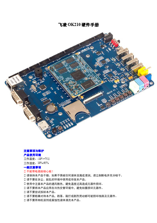
飞凌OK210硬件手册注意事项与维护产品使用环境工作温度:-10°-+75℃工作湿度:10%-95%一般注意事项℃ 不能带电插拔核心板!℃ 请保持本产品干燥。
如果不慎被任何液体泼溅或浸润,请立刻断电并充分晾干。
℃ 请不要在多尘、脏乱的环境中使用或存放本产品。
℃ 使用中注意本产品的通风散热,避免温度过高造成元器件损坏。
℃ 请不要将本产品应用在冷热交替环境中,避免结露损坏元器件。
℃ 请不要尝试拆卸本产品。
℃ 请不要粗暴对待本产品,跌落、敲打或剧烈晃动都可能损坏线路及元器件。
℃ 请不要用有机溶剂或腐蚀性液体清洗本产品。
℃ 请不要用颜料涂抹本产品。
℃ 擅自修改或使用未经授权的配件可能损坏本产品,由此造成的损坏将不给予保修。
如果产品出现故障,请联系飞凌技术服务部。
版权声明本手册所有权由保定市飞凌嵌入式有限公司独家持有。
未经本公司的书面许可,任何单位和个人无权以任何形式复制、传播、转载本手册的任何部分,否则一切后果由违者自负。
技术支持与更新技术支持说明技术支持范围:开发板软、硬件资源;判断开发板是否存在故障;如何烧写和更新系统;如何测试和运行开发板提供的程序。
技术支持时间:周一到周五:9:00—11:30,13:30—17:00。
公司按照国家法定节假日安排休息,在此期间无法提供技术支持,有问题请在论坛发帖。
保修范围及内容说明:1.凡飞凌出售的产品,除特殊说明外,提供一年的保修服务,(液晶屏提供三个月质保)。
2.保修期间凡产品出现质量问题,均可享受飞凌的免费维修服务,运费由双方均摊。
3.保修期满后出现性能故障和硬件问题,可与飞凌取得联系,飞凌提供有偿的维修服务,视具体情况而定。
注:凡是不在免费保修范围之内,邮费由客户来承担。
如客户不能提供购买时间的凭证,将开发板出厂日期视为购买日期。
维修周期:收到需维修的产品后,安排维修工程师测试、维修。
一般七个工作日即可修好(不包括邮寄路途上的时间)。
如有特殊情况,会向客户说明再与客户协商处理。
210系列紧凑网络开关快速引导说明书
210 SERIES COMPACT NETWORK SWITCHESQuick Start GuideAN-210-SW-C-8-PoE210 Series Compact Network SwitchesQuick Start GuideFCC WarningChanges or modifications not expressly approved by the party responsible for compliance could void the user’s authority to operate the equipment. This device complies with Part 15 of the FCC Rules. Operation is subject to the following two conditions: This device may not cause harmful interference, andThis device must accept any interference received, including interference that may cause undesired operation.12NOTE: This equipment has been tested and found to comply with the limits for a class B digital device, pursuant to part 15 of the FCC Rules. These limits are designed to provide reasonable protection against harmful interference in a residential installation. This equipment generates, uses and can radiate radio frequency energy and if not installed and used in accordance with the instructions, may cause harm-ful interference to radio communications. However, there is no guarantee that interference will not occur in a particular installation. If this equipment does cause harmful interference to radio or television reception, which can be determined by turning the equipment off and on, the user is encouraged to try to correct the interference by one or more of the following measures.Reorient or relocate the receiving antennaIncrease the separation between the equipment and receiverConnect the equipment into an outlet on a circuit different from that to which the receiver is connected Consult the dealer or an experienced radio/TV technician for helpThis equipment has been verified to comply with the limits for a class B computing device, pursuant to FCC Rules. In order to maintain compliance with FCC regulations, shielded cables must be used with this equipment. Operation with non-approved equipment or unshielded cables is likely to result in interference to radio and TV reception. The user is cautioned that changes and modifications made to the equip-ment without the approval of manufacturer could void the user’s authority to operate this equipment.CE WarningThis is a Class B product. In a domestic environment, this product may cause radio interference, in which case the user may be required to take adequate measures.UL StatementAll models have been evaluated by UL.This device is intended for indoor use only. It should not be connected to an Ethernet network with outside plant routing.The user must use the class I optical transceivers which conform to U.S. code of federal regulation, 21 CFR 1040. This equipment is only to be connected to PoE networks without routing to outside plants.Ensure the power cord is connected to a socket-outlet with earthing connection, or equivalent.NOTE: Maximum PoE output power of this equipment is 65W.Welcome to Araknis Networks™Thank you for choosing an Araknis 210-series Compact Network Switch. This PoE-powered switch features Gigabit connectivity on all ports, updated modern aesthetics, and a level of control (Websmart) rarely seen in managedsolutions. The Araknis 210-series switch is a sleek and highly capable addition to any network.Features• Gigabit Ethernet• 8 × 802.3af/at PoE-OUT Ports• 2 × SFP Uplink 1000BASE-X Ports• Multi-mounting can design• Websmart switch• OvrC enabledDimensions (W x H x D)• 8 Port: 12.71" x 1.50" x 4.13"Operating T emperature• 32–122°F (0–50°C)Step 1: UnboxSwitch Quick Start GuideRubber Feet (4)Structured WiringCan Mounting Kitw/ Push Pins (2) Shelf Mount Kit:4 sets of:• Screw: M3 x 8mm• Hollow Screw: M6 x 8mm• Nut: M6 nut 4 wall anchors with M3 x16mm screwsSpare Can MountingPush Pins (4)Body: 8.5mm(D), 10.4mm(L),6.35mm(W)Pin: 8.5mm(D), 18.2mm(L),3.7mm(W)Step 2: Install210 compact switches feature several mounting options for easy setup in any scenario. See the following pages forspecific instructions.Shelf(use included rubber feet)WallStructured Wiring CanIEC Power CableMounting Shelf Installation(Due to its width, this model should span two mounting shelves. We do not recommend using only one.)NOTE: Connect SFP ports using Araknis SFP adapters for RJ45 or multi-mode fiber cables. SFP adapters sold separately.Step 3: ConnectComputerStep 4: PoE BudgetThe power budget for delivering Power over Ethernet limits the total number of watts available between all of the ports (limited to 30W total consumption on each port). Add the total number of watts consumed by all connected PoE devices to ensure that every thing can be powered, as illustrated in the example below.ModelPoE Budget AN-210-SW-C-8-POE65WT otal PoE Device Consumption =45W PoE Budget Left Available=20WT otal PoE Budget Available=65W 8W +++8W 12W14WStep 5: VerifyPower LED –O n: system is up. Off: system is down.1Gbps LED –O n: port connected at 1Gbps speed.Off: port is connected at 10/100Mbps speed.Link/Act LED –O n: port is connected to another device.Blinking: packets are running through the port.Off: port is not connected to a device.Step 6: Claim on OvrCWeb BrowserMobileOvrC provides remote firmware upgrades, real-time notifications, and intuitive customer management, right fromyour computer or mobile device. Setup is plug-and-play, with no port forwarding or DDNS address required. T o addthis device to your OvrC account:Connect the switch to the network (Internet access required).Log Into OvrC () or load the OvrC app.Add the device (MAC address and Service T ag numbers needed for authentication).(RJ-45 LEDs only)210 Series Compact Network SwitchesQuick Start GuidePro Tip: Rebooting the Switchfor 5 seconds, then release. The switch will power cycle andthe front status lights will flash.Factory Reset –P ress and hold the RESET button for 15 seconds until all LEDs turn solid. The switch will reboot and be reset to factorydefault settings.© 2020 Araknis Networks®200306-0951WarningThis product can expose you to chemicals including carbon black, which is known to the State of California to cause cancer. For more information go to .2-Y ear Limited WarrantyAraknis Networks® products have a 2-Y ear Limited Warranty. This warranty includes parts and labor repairs on all components found to be defective in material or workmanship under normal conditions of use. This warranty shall not apply to products that have been abused, modified, or disassembled. Products to be repaired under this warranty must be returned to a designated service center with prior notification and an assigned return authorization (RA) number. Contact technical support for an RA number.Contact InformationTechnical Support (866) 838-5052The latest version of this QSG may be found on the productpage support tab.。
PORIS-简易手册_PR-210NT门禁控制器_CHS_131019

PORIS-简易手册_PR-210NT门禁控制器_CHS_131019PR-210NT 快速操作设定,如下:系统开机当系统(指控制器及所连接的全部模组)打开电源后,设备本身会先自动故障检测,然后,控制器LCD 会显示【初始画面】,再转换成【初始时间】,控制器面板LED 灯会全亮,哔声消失后,就只剩POWER 和A 灯亮着。
面板按键说明使用者登入操作方式:按【MENU 】键,显示【System 】按[EN]键进入,显示【Login 】按[EN]键进入,显示【Password :_____】画面,输入操作员默认密码为[1234],输入后按[EN]键确认,若登入成功,则画面显示【Master OK 】,即表示已进入系统设定程序。
系统初始化-清除原有设定资料功能说明:本项功能为将控制器所有设定值(不含卡片)清除恢复成出厂默认状态。
启动功能菜单菜单确认与执行键(Enter Key )退出当前画面,回上一项功能画面向上翻页向下翻页数字键: : : : : :~操作方式:进入【System】按[EN]键,按上下翻页键选择【System Process】按[EN]键进入,按上下翻页键选择【System Init】按[EN]键进入,按上下翻页键选择【Init Sys[Yes]】按[EN]键确认,画面显示【Data Clr Restart.】,过几秒画面显示【Data Clr 1:Clear】这时按键上“1”键确认数据清除。
初始化结束会自动切换到日期时间显示画面。
控制器识别码(ID)设定功能说明:如果控制器只有一台,则本项设定可免(控制器出厂时ID皆设为001)。
当连线的控制器两台以上时,需要把控制器设置为不同的识别码(ID)。
操作方式:登入系统后按上下翻页键选择【System Process】按[EN]键进入,按上下翻页键选择【Control ID】按[EN]键进入,在画面【Control ID=001】中用数字键输入要设定的识别码ID,按[EN]键确认,设定完成。
力控单元NCFN (30-300 kN) 使用说明书

NC Joining Module NCFNfor Joining Operation with Single-Channel Control Systems2153A _000-669e -07.10Page 1/7This information corresponds to the current state of knowledge. Kistler reserves the right to make technical changes. Liability for consequential damage resulting NC Joining System©2007 ... 2010, Kistler Group, Eulachstrasse 22, 8408 Winterthur, Switzerland The NC joining module NCFN Type 2153A... with integrated strain gage force sensor for nominal forces of 30 ... 300 kN is excellent for use in assembly and joining processes monitored by force displacement.• Force feedback control • High velocity• Practical repeatability <0,01 mm• High measuring accuracy for all ranges• Active compensation of process compression for exact positioning• High overload capacity • Easy handlingDescriptionThe NC joining modules NCFN Type 2153A... consist of a ro-bust housing with an integral strain gage tension/compression force sensor. An absolute encoder for precise positioning is integrated in the drive motor. The motor is an electrically com-mutated AC servo motor which is driven by a servo controller. This servo controller provides constant speed, independant of load. Standard functions like block pressing, position pressing and force feedback controlled pressing as well as intermediate positioning are supported.The NC joining module NCFN can be operated with the In-draDrive servo controller in combination with the DMF-P A300 NCF Type 4734A..., DMF-P A310 Universal Type 4740A... or with the NC Compact Type 2159A. Monitoring of the work area of the screw drive is assumed the electronics in the servo controller.The functional principle of the individual systems is described on the following pages. A field bus slave interface is used to connect the system to the system control, the Ethernet con-nection, including output of QA data.ApplicationNC joining module NCFN Type 2153A... is excellent for appli-cations in assembly and joining tasks in automated production plants and manual-work places.Vertical and horizontal installation is possible and is performed by flange or wall mounting. Tapped holes for tool mounting are located at the tappet of the ball bearing screw (Fig. 1).Type 2153A...Page 2/72153A _000-669e -07.10This information corresponds to the current state of knowledge. Kistler reserves the right to make technical changes. Liability for consequential damage resulting ©2007 ... 2010, Kistler Group, Eulachstrasse 22, 8408 Winterthur, Switzerland Tel.+41522241111,Fax+41522241414,****************, Technical DataDimensions mm Fig. 1 Assembly Wall orflange assembly Weightkg refer dimension Max. tool weight*kg refer dimensionDirection of measurement tension/compressionNominal force kN 30, 60,100, 200, 300Stroke lengthonly nominal force ≤100 kN mm 200 nominal force 30 ... 300 kN mm 400Anti rotate tool fitting Fig. 1Safety device optional V/A 24/3 to 5 1)Holding brake (standard) V/A 24/0,7 to 1,5 1)Max. speedNC joining module 300 kN mm/s 100 NC joining module 200 kN mm/s 140 NC joining module 100 kN mm/s 200 NC joining module 30, 60 kN mm/s 250Displacement sensor system absolute encoderResolution mm 0,001Force sensor strain gageAccuracy% <0,5Temperature range°C10 (40)Protection classIP54Life cycle ball screwcyclesapprox. 10 million(per defined drive profile)Servo Controller Bosch-Rexroth Type IndraDrive Standard Interface** Profibus Control voltage VDC/W 24 (19,2 ... 28,8)/24Power connection V 400 (400 ... 500) ±10 % Hz 50/60 ±2 %phase 3Evaluation Unit Type 4734A... or Type 4740A...Standard Interface Profibus SupplyVDC 24 ±10 %Evaluation UnitNC Compact Firmware Type 2159A Operating PanelType 2158ATo assure sufficient lubrication in case of strokes which are considerab-ly smaller than the nominal stroke one nominal stroke has to be made at regular intervals.* Possible radial forces must be considered independent of the mounting.** Dependent of system1)Dependent size/typePage 3/72153A _000-669e -07.10This information corresponds to the current state of knowledge. Kistler reserves the right to make technical changes. Liability for consequential damage resulting ©2007 ... 2010, Kistler Group, Eulachstrasse 22, 8408 Winterthur, Switzerland Tel.+41522241111,Fax+41522241414,****************,DimensionsAssembly may require an external guidance for the roller ram. Radial forces such as tool weight must be considered.Fig. 1: Dimensions NC joining module NCFN Type 2153A...** Dimensions with safety deviceTypeA A**B øJ øK C2 C3 G1 G2 P O R F1 F2 C1 X Y øV 2153A030200 1 042 1 237 528 90 120 50 5 148 150 100 100 M12x24 75 75 215 20 4,5 112153A030400 1 242 1 437 728 90 120 50 5 148 150 100 100 M12x24 75 75 215 20 4,5 112153A060200 1 150 1 345 544 110 150 50 5 177 180 130 130 M16x32 90 90 215 20 4,5 13,52153A060400 1 350 1 545 744 110 150 50 5 177 180 130 130 M16x32 90 90 215 20 4,5 13,52153A100200 1 332,5 1 557,5 640 160 195 50 5 227 230 170 170 M20x40 115 115 280 28 6 17,52153A100400 1 532,5 1 757,5 840 160 195 50 5 227 230 170 170 M20x40 115 115 280 28 6 17,52153A200400 1 732,5 1 957,5 968 160 200 50 5 247 250 190 190 M20x40 115 115 282 36 9 222153A3004001 885,52 110,4 1 035200240728297300210210M24x4815015037736926Type øL H D E Z M øT N øS W U Q Weight Tool weightøTK H7 H7 [kg] [kg]2153A030200 18 75 150 150 125 65 8x16 68 8x16 112,5 ° 8x45 ° M8x16 75 1002153A030400 18 75 150 150 125 65 8x16 68 8x16 112,5 ° 8x45 ° M8x16 95 1002153A060200 20 90 140 150 150 80 8x16 82 10x10 112,5 ° 8x45 ° M10x20 115 1002153A060400 20 90 140 150 150 80 8x16 82 10x10 112,5 ° 8x45 ° M10x20 140 1002153A100200 26 80 204 180 200 120 10x20 106 12x24 112,5 ° 8x45 ° M16x32 225 1002153A100400 26 80 204 180 200 120 10x20 106 12x24 112,5 ° 8x45 ° M16x32 270 1002153A200400 33 100 200 200 205 120 10x20 115 12x24 112,5 ° 8x45 ° M16x32 355 1002153A300400 40 145 270 250 252 140 12x24 135 12x24 112,5 °8x45 ° M16x32 794 150Page 4/72153A _000-669e -07.10This information corresponds to the current state of knowledge. Kistler reserves the right to make technical changes. Liability for consequential damage resulting ©2007 ... 2010, Kistler Group, Eulachstrasse 22, 8408 Winterthur, Switzerland Tel.+41522241111,Fax+41522241414,****************, Functional Principle with DMF-P A300 NCF Type 4734A...Motor Control FeedbackFig. 2: Functional principle of NC joining system with NC joining module NCFN Type 2153A... and DMF-P A300 NCF Type 4734A...Included Accessories• NoneOptional AccessoriesType/Art. No.• Servo controller for Type 2153A... with integrated safety option IndraDrive 54 A PB S2 MPH07 KSM035374• Servo controller for Type 2153A... with integrated safety option IndraDrive 70 A PB S2 MPH07 KSM035377• Servo controller for Type 2153A... with integrated safety option IndraDrive 100 A PB S2 MPH07 KSM035362• Evaluation unit DMF-P A300 NCF 4734A...• Wall housing evaluation unit 4734AWDY1...• Desktop housing evaluation unit 4734ATDY1...• Panel housing evaluation unit 4734AEDY1...CableType/Art. No.• NCFN 30 motor cable,length 5 m RKL4309 KSM303490-5• NCFN 60 motor cable,length 5 m RKL4314 KSM305640-5• NCFN 100 motor cable,length 5 m RKL4323KSM307530-5• NCFN 200/300 motor cable,length 5 m RKL4329KSM316330-5• NCFN MSK Feedback cable,length 5 m RKG4200KSM303500-5• NCF cable SSI displacementIndraDrive, length 5 mKSM301750-5• Data cable IndraDrive, length 5 m KSM301640-5• NCFN Strain gage force cable, length 5 m KSM206000-5• NCF cable analog force signal, length 5 m KSM301760-5• NCF cable XTE, YTE IndraDrive, length 5 m KSM314030-5Other length on request.Machine Interface SPS Configuration, Programming Evaluation and Visualization DMF-P A300 NCF Type 4734A...Monitoring and Evaluation SystemPrinterPCEthernet Interface CSV, I-P .M. ProtocolQ-DASNC Joining Module NCFN Type 2153A...AC Servo MotorThreaded Spindle Absolute Encoder Servo ControllerPage 5/72153A _000-669e -07.10This information corresponds to the current state of knowledge. Kistler reserves the right to make technical changes. Liability for consequential damage resulting ©2007 ... 2010, Kistler Group, Eulachstrasse 22, 8408 Winterthur, Switzerland Tel.+41522241111,Fax+41522241414,****************, Fig. 3: Functional principle of NC joining system with NC joining module NCFN Type 2153A... and DMF-P A310 Universal Type 4740A...Included Accessories• NoneOptional Accessories Type/Art. No.• Servo controller IndraDrive 54 A EI S2 MPC07, NCFN 30 kN KSM036444• Servo controller IndraDrive 70 A EIS2 MPC07, NCFN 60/100 kN KSM036448• Servo controller IndraDrive 100 A EIS2 MPC07, NCFN 200/300 kN KSM036453 • Evaluation unit DMF-P A310 Universal 4740A...• Wall housing evaluation unit 4740AWY1...• Desktop housing evaluation unit 4740ATY1...• Panel housing evaluation unit4740AEY1...CableType/Art. No.• NCFN 30 motor cable,length 5 m RKL4309 KSM303490-5• NCFN 60 motor cable,length 5 m RKL4314 KSM305640-5• NCFN 100 motor cable,length 5 m RKL4323KSM307530-5• NCFN 200/300 motor cable,length 5 m RKL4329KSM316330-5• NCFN MSK Feedback cable,length 5 m RKG4200KSM303500-5• NCFN Strain gage force cable, length 5 m KSM206000-5• Network cable A310 EtherNet/IP , length 5 m KSM036457-5• N etwork cable A310 EtherNet/IP , length 10 m KSM036458-10• N etwork cable A310 EtherNet/IP , length 20 mKSM036459-20• Network cable A310 EtherNet/IP , length 30 mKSM036460-30Other length on request.Servo ControllerMotor Control FeedbackMachine Interface SPS Configuration, Programming Evaluation and VisualizationDMF-P A310 Universal Type 4740A...Monitoring and Evaluation SystemPrinterPCEthernet Interface CSV, I-P .M. ProtocolQ-DASFunctional Principle with DMF-P A310 Universal Type 4740A...AC Servo MotorThreaded Spindle Absolute EncoderPage 6/72153A _000-669e -07.10This information corresponds to the current state of knowledge. Kistler reserves the right to make technical changes. Liability for consequential damage resulting ©2007 ... 2010, Kistler Group, Eulachstrasse 22, 8408 Winterthur, Switzerland Tel.+41522241111,Fax+41522241414,****************,Functional Principle with NC CompactIncluded Accessories• NoneOptional AccessoriesType/Art. No.• Servo controller for Type 2153A... with integrated safety optionIndraDrive 54 A PB S2 MPH07 KSM035374• Servo controller for Type 2153A... with integrated safety optionIndraDrive 70 A PB S2 MPH07 KSM035377• Servo controller for Type 2153A... with integrated safety optionIndraDrive 100 A PB S2 MPH07 KSM035362• NC Compact Firmware2159A • NC Compact Operating Panel 2158A • Measuring amplifierfor strain gage sensors 4701AQ07CableType/Art. No.• NCFN 30 motor cable,length 5 m RKL4309 KSM303490-5• NCFN 60 motor cable,length 5 m RKL4314 KSM305640-5• NCFN 100 motor cable,length 5 m RKL4323KSM307530-5• NCFN 200/300 motor cable,length 5 m RKL4329KSM316330-5• NCFN MSK Feedback cable,length 5 m RKG4200KSM303500-5• NCFN Strain gage force cable,length 5 mKSM206000-5• Data cable IndraDrive, length 5 m KSM301640-5• Cable DMS free/KD6 Tuchel KSM103820-5Other length on request.ProfibusCustomer PLCRS-232CNC Compact Firmware Type 2159AOperating Panel Type 2158AFig. 4: Functional principle of NC joining system with NC joining module NCFN Type 2153A... and NC Compact Type 2158A and Type 2159ANote:Other Fieldbus Interfaces e.g. EtherNet/IP , Profinet, etc. on request.NC Joining Module NCFN Type 2153A...Measuring Amplifier Strain Gage Sensors Type 4701AQ07Page 7/72153A _000-669e -07.10This information corresponds to the current state of knowledge. Kistler reserves the right to make technical changes. Liability for consequential damage resulting ©2007 ... 2010, Kistler Group, Eulachstrasse 22, 8408 Winterthur, Switzerland Tel.+41522241111,Fax+41522241414,****************,Ordering KeyOrdering Example: Type 2153A0602003HGNC joining module NCFN Type 2153A..., nominal force 60 kN ,stroke 200 mm, speed 250 mm/s, holding brake H , configuration G1)Safety device is optional。
5.NEC数字放映产品维护手册_V1.5_20190104
1. 出气口(灯泡) 2. 出风口 3. 控制面板 4. 灯泡电源线 5. 板卡插槽 6. 总电源开关 7. 网络接口 8. 蜂鸣器 9. 入气口(灯泡冷却) 10. 入气口(放映机电路和光学元器件) 11. 镜头 12. 联锁接口 13. 转换镜头底座固件 14. 灯电源控制信号线 15. 机头供电线缆
10.选择正确 音频制式
11.取下放映 机镜头盖
12.打开放映 机光源
14.放映播放 片源
13.开启光闸
放映操作流程
放映设备关闭操作顺序
1.放映结束
2.操作服务器停 止播放
3.关闭放映机光 源
6.关闭TMS系 统(如必要, 先主机后片库)
5.关闭还音系统
4.关闭服务器
7.关闭放映机
8.关闭3D系统
快速开启放映机-NC1200C/NC2000C
30秒不操作后控制面板被锁定(“KEY LOCK”键变成橙色) 4. 此时可以按下“KEY LOCK”键1秒或更长,使得其变成白 色,用户可以在此时操控控制面板上的按键。
注!“Key Lock”的锁定模式可以 在DCC软件的设置菜单中更改(常锁 /不锁/自动锁)
后端
放映机介绍
放映机各个位置介绍(NC1200C/NC2000C/N2300S/NC3200S/NC3240S)
1. 外部控制接口(GP I/O)D-Sub 37P 2. 3D接口(3D)(D-Sub15P) 3. PC控制接口(RS-232C)D-Sub 9P 4. USB接口(USB)A型 5. 遥控设备接口(立体声迷你插孔) 6. 网络控制接口(LAN) RJ-45 7. 设备管理指示灯 8. HDSDI 输入接口(BNC) 9. DVI-D 输入接口(DVI-D)24P 10. 插槽B 11. 插槽A
nec sl2100 2w mlt 用户指南说明书
. Please read this manual carefully before operatingthis product and save this manual for future use.Thank you for purchasing NEC SL2100 system.Due to the flexibility built into the system, your Dialing Codes and Feature Capacities may differfrom those in this guide. Check with your NEC Authorized Supplier / System Administrator and make a note of any differences.When installing the handset :1. Make sure the handset cord is plugged into the handset jack on the telephone base.2. The line cord routes through the channel on the telephone base.3. Alternatively the line cord can route through the channel on the telephone legs.To set the low viewing angle position:1. Fold the legs all the way back.To set the high viewing angle position:1. Flip up the two leg supports.2. Fold the legs back until the supports contact the base.* 12 Programmable Function Keys are available for IP7WW-12TXH-B1 TEL. 24 Programmable Function Keys are available for IP7WW-24TXH-B1 TEL. ** The illustration shows IP7WW-24TXH-B1 TEL.Dial Keys can be used for Handsfree dialing/ monitoring. LED on key lights whenkey is active. Redial Key Volume (UP) Key orVolume (DOWN) KeySpeakerCall Indicator LampThis lamp flashes fast when a call is ringing and flashes slower when a message has been left. Alphanumeric Display The LCD has 3 lines, 24 characters with backlight.Soft Keys **The Soft Keys show the available features for your current activity. Any feature shown at the bottom of the LCD is available.Help KeyThe user can press this key followed by a programmable key to check what Line or Programmable Feature is assigned on the key.Programmable Function Keys Flexible Line keys or Feature Keys assigned by the System Administrator.Flash KeyPress key to finish an outside call and hear the dial tone.Transfer KeyAllows the extension user to transfer established calls to another extension.DND Key (Do Not Disturb)Setup a Do Not Disturb during a call or in idle state.Mute (Microphone) Key Mute handset or Handsfree Microphone. LED lights when microphone is muted.Clear/Back Key Press this key to cancel the current action or delete a character.Cursor KeyAccess various features with simple operation.Handsfree Options- Handsfree lets you place and answer calls by pressing “Speaker” instead of using the handset. - With Automatic Handsfree, you can press a Speaker Key without lifting the handset. Normally, you have Automatic Handsfree.- Use Handsfree Answerback to answer a voice-announced Intercom call by speaking toward your phone without lifting the handset.• To change the Trunk Access Code, Ask your NEC Authorized Supplier for the details.• In the default setting, Programmable Function Key No. 1 to 12 is assigned as “Trunk” Key. If you want to assign DSS Keys at the unused Trunk Keys, these unused keys should be erased by “752 + 000” operation before the above operation.• For the DSS Key, the extension status can be indicated on the BLF . (idle : extinguished, Busy : lit)• When you register a telephone number, the Trunk Access Code should be added in front of the number. • Up to 36 digits dialing can be registered, but the name can not be registered.• If you want to continue the operation, press Programmable Function Key instead of Speaker Key to finish. • One-Touch Keys can be assigned by Soft Key operation as well.⏹ Programmable Function KeysProgrammable Function Keys can be assigned as “Trunk” Key and/or other Function Keys. You can just press the function key to activate the assigned function without dialing the Service Code. Function Code & Add Data• There are 2 levels of Function Keys. (General Keys : assigned by 751, Appearance Keys : assigned by 752)• Appearance Keys have priority. You can overwrite the Appearance Key at the General Key.• If you want to overwrite the General Key at the Appearance Key, you have to erase the Appearance Key by dialing “752 + 000” before General Key assignment.• In the default setting, Programmable Function Key No. 1 to 12 is assigned as “Trunk” Key. If you want to assign Function Keys (General) at the unused Trunk Keys, these unused keys should be erased by “752 + 000” operation.• Programmable Function Keys can be erased by dialing “752 + 000” or “751 + 00”. • Programmable Function Keys can be assigned by Soft Key operation as well.⏹ DSS / One-Touch KeysProgrammable Function Keys can be assigned as DSS (Direct Station Selection) or One-Touch Keys. You can place an Outside / Intercom Call by just pressing this key without dialing the number. Telephone NumberTrunk Access Code Extension Number725715??71510?????90⏹ Abbreviated Dial (Speed Dial) RegistrationName• The number of digits dialed for Bin No. depends on the system setting. (0-9<Only Group ABB> / 00-99 / 000-999)• System setting is necessary for Group ABB function. Ask your NEC Authorized Supplier for the details. • Name can be entered by Dial Pad Keys. (See below)• Up to 36 digits dialing can be registered, and up to 12 characters can be registered as name. • If you want to continue the operation, dial Bin No. instead of Speaker Key to finish. • You can skip to enter the name. (No enter any character, then press “Hold” Key).• You can erase the registered number & name by pressing “Exit” Key after dialing Bin No.. • Common Abbreviated Dial can be registered using Soft Key / Cursor Key operations..When you enter a name, use Dial Pad Keys to enter letters as below. For example, press “2” key once for “A”, twice for “B”, etc…⏹ Entering Alphanumeric CharactersGroup ABB735745????????1234567890#⏹ Place an Outside Call <Quick Access>Telephone Number⏹ Place an Intercom Call <Dial Access>• Listen to the Dial Tone before dialing a Telephone Number.• You can have function keys for Trunks or Trunk Groups. Ask your NEC Authorized Supplier for the details.⏹ Place an Outside Call <Access by Code>Telephone NumberTrunk Access CodeTrunk Group No.• To change the Trunk Access Code, Ask your NEC Authorized Supplier for the details. • Listen to the Dial Tone before dialing a Telephone Number.• If the Trunk Group number is greater than 10, you should enter 2 digits (e.g. 11: Group 11) after dialing “704”. Ask your NEC Authorized Supplier for the details.• Ask your NEC Authorized Supplier for the Trunk Number dialing digits.• Your call will ring or voice-announce. If you hear ringing, wait for an answer. If you hear a beep, begin speaking. Dialing “1” changes voice/ring mode. (in case the destination is Multi-line Terminal)??????407??????909#0#⏹ Directory DialingPress several times to search⏹ Last Number DialingPress several times to search⏹ Callback by Received Number• The system retains the last 10 numbers dialed which can be reviewed and redialed. • To cancel the Redial List operation, press “Clear/Back” Key.• Caller-ID function is required to use this operation for outside calls. Ask your NEC Authorized Supplier for more details.• To cancel the Callback operation, press “Clear/Back” Key.Press several times to search• After searching the desired destination, press “Enter” Key to confirm the telephone number before lifting the handset, if necessary.• You can enter more Characters (up to 12) to make desired destination’s search even more specific. • You can also search the desired destination without entering the Characters. (press Cursor Keys only) • To cancel the Directory Dialing operation, press “Clear/Back” Key. • Directory Dialing can be activated by Soft Key operation as well.5#⏹Abbreviated (Speed) Dialing <for Outside>• The digit of Bin No. depends on the system setting. (0-9 <Only Group ABB> / 00-99 / 000-999) • Telephone Numbers shall be pre-registered to the system.• System setting is necessary for Group ABB function. Ask your NEC Authorized Supplier for the details.• When you assign the Common ABB Key on the Programmable Function Key, “Press HOLD” is required after dialing the Function Code 27.⏹ One-Touch / DSS Call• Telephone / Extension number should be pre-registered to a One-Touch / DSS Key. • Trunk Access Code should be added in front of the Telephone number.2#??4#??⏹ Set Camp On / Callback• Camp OnIntercom Call - when you hear ringing, wait for the called party to answer. Outside Call - when you hear Dial Tone, begin telephone number dialing.• Callback Intercom Call - when your terminal starts the ringing, lift handset and wait for the called partyto answer.Outside Call - when your terminal starts the ringing, lift handset, hear Dial Tone, and begin telephone number dialing.• This function is applicable in case all trunks are busy condition. (not applicable for dialed outside party busy)⏹ Cancel Camp On / Callback⏹ Repeat Dialing <Outside Call Only>• When the Repeat Dialing is set, Repeat Dial Key shall flash and the system automatically and periodically redials a call. Repeat duration is programmable. Ask your NEC Authorized Supplier for the details. • You should lift the handset when the called party answered. • Press flashing Repeat Dial Key to cancel.5777⏹Set a Message Waiting⏹ Cancel Message WaitingExtension Number• When you set a MW, the called party’s Indicator displays as per setting.⏹ Answer a Message Waiting (Your terminal’s Indicator displays as per setting)177???377• When you answer a MW, the Indicator automatically goes off when the called party answers. • If multiple message are in queue, you can select the desired party by pressing Up key after dialing “, 0”, ifseveral number of Message Waiting has been set.⏹ Answering an Outside Call⏹ Picking up a Call for other ExtensionsExtension Number• System setting is necessary to create a Call Pickup Group. Ask your NEC Authorized Supplier for the details.• Confirm the status of Mute Key if you want to answer by Handsfree. (Mute On : LED On, Mute Off : LED Off)⏹ Answering an Intercom Call• Intercom Call Mode (Signal or Voice) can be set at your terminal by : “Signal”: Speaker -> 723 “Voice”: Speaker -> 721• Confirm the status of Mute Key if you want to answer by Handsfree. (Mute On : LED On, Mute Off : LED Off)#976??⏹ Holding a Call / Retrieving a Held Call• When on an Intercom, the call is held as “Exclusive Hold” on your terminal.• This operation puts your outside call on System Hold. Other extension users can take the call off Hold.⏹ Retrieve a Held Outside Call• Ask your NEC Authorized Supplier for the details about your Trunk Number dialing digits.⏹ Transferring a Call to the other Extension⏹ Holding a Call Exclusively• This operation puts your outside call on Exclusive Hold. Other extension user can not take the call off Hold.• If your terminal has DSS/One-Touch key, just press it instead of “HOLD” and “Extension Number” dialing.??267??⏹ Do Not Disturb (DND)1234•When you set DND function, DND Key shall be lit and the Internal Dial Tone pattern shall be changed.⏹ ConferenceExtension Number?Telephone Number •You can repeat this operation to add more parties.•You may be able to have up to 16 parties (include your terminal). You may need to adjust the volume level due to the Environment where calls are placed. Ask your NEC Authorized Supplier for the details.Extension NumberSetWhen you set Call Forward / Follow Me, the destination extension is displayed on the LCD, and the Internal Dial Tone pattern shall be changed (Call Forward / Follow Me can be set by Soft Key).Call Forwarding / Follow MeExtension NumberSetExtension NumberSetExtension NumberSet174???1274???1??????11374474Call Forwarding / Follow Me (Cont’d)Extension NumberSetExtension NumberCancelSet??????67457411Cancel“Menu” Soft Key⏹ “Dir” Soft Key⏹ “VM” Soft Key (Option)“CL” Soft Key⏹ Soft Key Operations during Off-Hook condition⏹ Soft Key Operations during Intercom Calling⏹ Soft Key Operations after establishing an Intercom Call⏹ Soft Key Operations during Outside CallMenu Structure when PRG15-02-60 is set to Advanced Mode 1110 : Missed CallSystem setting is necessary to use Built-In Automated Attendant. Ask your NEC Authorized Supplier for the details.Stop REC⏹ Record / Listen / Erase Answering Messages• Up to 100 types of messages can be recorded. • The Message length can not exceed 4 minutes.RecordErase(001 – 100)661???????753#Log-On to the In-MailSystem setting is necessary to use In-Mail (Voice Mail) feature. Ask your NEC Authorized Supplier for the details.????????Call Forward to Voice Mail1??????????111474374274174⏹ Mailbox Greeting• Selected Greeting (one of three) shall be made active.⏹ Mailbox Security Code※ The type of Security Code can be assigned as below.- Dial 4 digits Security Code followed by “7”: Security Code for all log-on- Dial 4 digits Security Code followed by “6”: Security Code for remote log-on only • System Administrator can delete a Mailbox Security Code.4?753####6777???Listen to Left Messages in your Mailbox??5????5????◆ Instruction Menu Message are used as the Automated Attendant Main Greetings (e.g. Day Mode greeting, Night Mode greeting, etc)▪To record an instruction Menu from the System Administrator Menu, dial the digit 4 (Instruction Menu Messages). Dial the mailbox number (001 – 032).-Press the digit 5 to Listen to the message. -Press the digit 7 to Record the message. -Press the digit 3 to Delete the message.-Press # to return to the System Administrator Menu.◆ Announcement Message are used to announce general information to callers such as directions, hours of operation, etc.▪To record an Announcement Message from the System Administrator Menu, dial the digit 2 (Announcement Messages). Dial the mailbox number (001 – 032). -Press the digit 5 to Listen to the message. -Press the digit 7 to Record the message. -Press the digit 3 to Delete the message.-Press # to return to the System Administrator Menu.◆ Distribution List is a list of extensions set to receive a single voice mail message. Any message left in the distribution mailbox will be sent to all extensions in the list.▪To review or modify the Distribution List from the System Administrator Menu, dial the digit 5 (Distribution List). Dial the mailbox number (001 – 032) to be modified.. ►Press the digit 6 to Review or Modify the list.-Press the digit 2 to Add an extension to the distribution list. -Press the digit 3 to Delete the current extension from the list. -Press the digit 6 to step to the Next entry.-Press # to return to the System Administrator Menu.►Press the digit 76 to record a Name for the distribution list. -Press the digit 5 to Listen to the name. -Press the digit 7 to Record a new name. -Press the digit 3 to Delete the name. The following administrative features are only available at the system administrator’s extension (extension 101 at default). Ask your NEC Authorized Supplier for details on how to become a system administrator..Log-In to the In-Mail????????◆Subscriber Maintenance is used to modify the subscriber mailboxes.▪To modify a Subscriber Mailbox from the System Administrator Menu, dial the digit 7 (Subscriber Maintenance).Dial the extension number of the mailbox you wish to modify.-Press the digit 32 to Delete all messages.-Press the digit 34 to Delete the mailbox greeting.-Press the digit 36 to Delete to the mailbox name.-Press the digit 7 to Delete the security code.-Press the digit 6 to Record a new name.-Press # to return to the System Administrator Menu.◆Answer Schedule Override provides alternate answering for the Automated Attendant by sending calls to aspecified Override mailbox, when enabled. As an example you can use the Answering Schedule Override to provide Holiday and Bad Weather closing announcements.▪To modify the Answer Schedule Override from the System Administrator Menu dial 6 (Answer Scheduleoverride).Dial the answer table number (01-16) you wish to override.-Press the digit 6 to toggle On/Off the answer schedule table.-Press the digit 2 to enter a New answer schedule override mailbox. Enter the override mailbox number (001-032 or a valid subscriber extension). The override mailbox can be an announcement, call routing box, or asubscriber box.-Press # to return to the System Administrator Menu.◆Mailbox Announcement Message is a message recorded by the system administrator that plays to eachsubscriber when they log into their mailbox. This message will play each time the subscriber logs into their box until it expires, is deleted, or is made inactive by the system administrator.▪To record and modify the Mailbox Announcement Message from the System Administrator Menu, dial the digit 3 (Mailbox Announcement Message).-Press the digit 5 to Listen to the mailbox announcement message.-Press the digit 7 to Record a new mailbox announcement message.-Press the digit 3 to Delete the mailbox announcement message.-Press the digit 2 to Specify the amount of days the message is active. Enter * for an indefinite amount of days or enter 01-99 for 1-99 days.-Press # to return to the System Administrator Menu.◆Voice Mail Version will play a message indicating the software level of the voice mail.▪To hear the current Voice Mail Version from the System Administrator Menu, dial the digit 8 (Voice mail Version).Multiline TerminalUser Guide GVT-025183-301-00 NA。
SYRIS SY210NT系列 快速入门说明书
SYRIS SY210NT系列快速入门操作手册Control up to 4 doors with in/out readerBaud rate 2,400 - 115,200 bpsSY210NT系列基本选单结构图SY210NT Serial Basic Menu Structure为了协助使用者熟悉SY210控制器系列的操作流程,在此先列出SY210的基本选单结构图。
上图中白色方块为『登入流程』,开始操作前必须优先执行,才能进入深灰色『主选单目录』及浅灰色『次选单目录』,请参考图标的按键与箭头动向。
次选单下的功能列表将于以下的文件中说明,此处暂不赘述。
目录项次内容页次01 注意事项 302 登入、注销步骤 403 模块设定 (卡片阅读机设定) 504 卡片增加、删除与编辑805 指纹增加与删除1206 设定控制器ID (多部控制器联机时) 1707 流程控制 (开门按钮设定) 1901‧注意事项安装前:当您准备安装SY210系列控制器之前,请先打开控制器背盖(TSN、SSN型号),确认机板右上角锂电池的白色阻隔胶片已移除。
于第一次连接电源时,控制器所有灯号闪烁并发出连续声响,请依控制器LCD 屏幕显示(1:Clear)按下1键进行系统重置。
设定时:本公司出厂的控制器与卡片阅读机初始ID皆设定为1。
当需要多部联机时必须先设定ID,以避免ID重复导致传输失败。
卡片阅读机ID设定方式请参考第5页『模块设定』。
控制器ID设定请参考第17页『设定控制器ID』。
02‧登入、注销步骤SY210NT 控制器必须先完成登入步骤才能进入功能选单。
当使用者停止操作,控制器静置约2分钟之后会自行注销。
但为确保门禁安全,请于设定完成后执行注销步骤。
登入步骤输入按键控制器LCD显示备考MENU SystemEN LoginEN Password等待密码输入OK1+2+3+4+EN MasterSetup灯号亮,已进入登入状态注销步骤(登入状态时)输入按键控制器LCD显示备考MENU SystemEN Login▼ LogoutEN 显示日期、时间Setup灯号熄,已完成注销步骤*以下步骤皆预设为已登录状态,不再重复说明登录步骤。
科肯P100系列用户手册中文版
-8-
P100 系列
用户手册
PDM20全系列机型三线式10V传感器接线图示 2.三线制 10V 压力传感器接线图
压力变送器
型号:PT1101 电源:10VDC 量程:0-1Mpa 输出:4-20mA
电源线:红色 信号线:绿色V0与GND之间电是否与设定值相等。
2.5 接线图
1. 远传压力表接线图 PDM20全系列机型远传压力表接线图示
远传压力表
如果条件允许,连接前用万用表测量 +V0与GND之间电是否与设定值相等。
M1 M2 GND +VO AI
1
1号脚接信号地端子-GND
2
2号脚接电源端子-+VO
3
3号脚接信号接收端子-AI
地
1.安装接线 按图示接好主电源线与
第三章 快速调试................................................................................................. 11 3.1 参数设置................................................................................................11 3.2 水泵转向确认........................................................................................11
第二章 外观及接线............................................................................................... 7 2.1 型号说明...................................................................................................7 2.2 安装尺寸..................................................................................................7 2.3 主电路与控制端子接线图......................................................................8 2.4 端子标识及说明......................................................................................8 2.5 接线图......................................................................................................9
- 1、下载文档前请自行甄别文档内容的完整性,平台不提供额外的编辑、内容补充、找答案等附加服务。
- 2、"仅部分预览"的文档,不可在线预览部分如存在完整性等问题,可反馈申请退款(可完整预览的文档不适用该条件!)。
- 3、如文档侵犯您的权益,请联系客服反馈,我们会尽快为您处理(人工客服工作时间:9:00-18:30)。
注 (1) 本手册的内容未经允许不得部分或整个复制。 (2) 本手册的内容若有改变, 恕不另行通知。 (3) 本手册经过精心编纂, 但是如果您发现任何有疑问、 错误或漏掉的地方, 请与我们联系。 (4) 除第 (3) 条外, NEC 将不负责对由于使用该投影机而导致的任何经济损失或其它问题的索赔。
重要信息
属物体插入投影机内。若发现有物体掉入投影机内部,须立即断开电源,然后委托有维修资格的维修服务人员取出 物体。
• 切勿在投影机上面放置任何物体。 • 雷雨天不要触摸电源线插头。此举可能引起电击或者火灾。 • 投影机规定操作电源为 200-240 伏特 50/60 赫兹交流电。在使用投影机之前,须确认所用电源是否符合本投
更换灯泡
• 请完全依照第 65 页所提供的指示来更换灯泡。 • 当出现 [ 灯泡已达到使用寿命极限,请更换灯泡。 ] 字样时请务必更换灯泡。若在灯泡达到使用寿命极限之后仍继 续使用,灯泡可能会碎裂,玻璃片会散落在灯架之内。切勿触摸这些碎片,以免造成伤害。
此种情况发生时,请联系您的经销商来更换灯泡。
- 不稳定的车、架子、或桌子。 - 靠近水、浴池或潮湿的房间。 - 阳光直射、靠近加热装置或热辐射装置的地方。 - 多尘、多烟或多蒸汽的环境。 - 纸张或布上、垫子或地毯上。 • 若您欲将投影机安装在天花板上 : - 切勿自行安装。 - 安装工作必须委托有资格的技术人员进行,以确保规范操作,并可防患人身伤害。 - 此外,天花板必须牢固,能够充分承受投影机的重量,而且必须依照当地建筑规则进行安装。 - 详情请向您的经销商查询。
10˚
关于火灾和电击的注意事项
• 为避免热气积聚在投影机内部,须确保通风状态良好且通风口不被阻塞。在投影机和墙壁之间至少需留出 10 厘米 间隔。
• 勿触摸前面的排气口,因为投影机启动和关闭瞬间可能发热。
• 勿让纸夹和纸屑等异物掉入投影机内。切勿试图找回可能掉入投影机内的任何物品。切勿将铁丝或者螺丝起子等金
• 如果在海拔低于 1700 米的地方使用本投影机时设置为 [ 高海拔 ],可能会造成灯泡过冷,从而导致影像闪动。这时, 请将 [ 风扇模式 ] 切换为 [ 自动 ]。 • 在海拔约为 1700 米或更高的地方使用本投影机,可能会缩短灯泡等光学部件的使用寿命。
关于原始投射图片的版权问题 :
请注意,在咖啡厅或宾馆等场地使用本投影机以作商业或吸引公众注意力用途时,若使用下列功能使屏幕影像出现压 缩或伸展,可能会侵犯版权法保护下的版权拥有者的权益。 [ 显示宽高比 ]、[ 梯形修正 ]、放大功能以及其他类似功能。
iv
重要信息 关于高海拔模式 • 在海拔约为 1700 米或更高的地方使用本投影机时,请将 [ 风扇模式 ] 设置为 [ 高海拔 ]。 • 如果在海拔约为 1700 米或更高的地方使用本投影机时没有设置为 [ 高海拔 ],可能造成投影机过热并且保护器可能
会使投影机关闭。遇此情况,请等待几分钟后再打开投影机。
安全注意
注意事项
开始使用 NP215+/NP210+/NP115+/NP110+ 投影机之前,请仔细阅读本手册并妥善保管以便将来查阅。 注意 欲关掉主电源,必须将插头从电源插座拔出。 电源插座应该尽量安装在靠近投影机,并易于操作之处。
注意 为防触电,请勿打开机壳。 投影机内部有高压元件。 有关维修事宜请委托给有资格的 NEC 维修服务人员。 本符号用来警告用户 : 投影机内的未绝缘电压可能足以导致电击。因此,请勿接触投影机内部的任何部件, 以防发生危险。 本符号用来提醒用户 : 有关投影机操作及维修的重要信息已随机附送。 应仔细阅读本信息,以免发生问题。
遥控器操作注意事项
• 请小心使用遥控器。 • • • • • • •
如果遥控器弄湿应立刻擦干。 避免放在过热或过于潮湿的地方。 切勿加热,拆卸或把电池投入火中。 如果长时间不使用遥控器需取出电池。 确保电池的正负极 (+/-) 方向排列正确。 切勿将新旧电池混用,或将不同类型的电池混用。 请根据当地法规处理废旧电池。
iiiBiblioteka 重要信息• • • •
移动投影机时拔掉电源线或其它电线。 清洁机箱或换灯泡前应关闭投影机并拔掉电源线。 如果投影机很长时间不使用,请关闭投影机并拔掉电源线。 当使用 LAN 导线时 ( 仅限于 NP215+) : 为了确保安全,切勿将投影机连接到外围设备配线有可能超压的连接器上。 注意 • 切勿将投影机的俯仰脚用于规定以外的用途。不合理使用如用俯仰脚提起或者 ( 在墙壁或者天花板上 ) 挂起投 影机会对投影机造成损坏。 • 切勿用软包装裹投影机以包裹寄送服务或货物船运发送投影机。装在软包里的投影机可能会因此破损。 请在风扇模式中选择 [ 高速 ]。( 从菜单中选择 [ 设置 ] → [ 可选项 (1)] → [ 风扇模式 ] • 欲连续数天使用投影机时, → [ 高速 ]。) • 切勿触摸左前方 ( 从前面看 ) 的排气口,因为投影机启动和关闭瞬间可能发热。 • 启动灯亮 60 秒内或 POWER 指示灯闪烁绿色时切勿关闭 ( 交流 ) 电源。这样做可能导致缩短灯泡使用寿命。
1 包装箱内有哪些物件?........................................................................................... 1 投影机介绍 ......................................................................................................... 2 恭喜您购买本投影机 ....................................................................................... 2 供您享用的产品性能 ....................................................................................... 2 关于该用户手册 .............................................................................................. 3 投影机各部位名称................................................................................................ 4 正面/顶部 ....................................................................................................... 4 背面 .............................................................................................................. 4 顶部功能 ........................................................................................................ 5 终端面板的功能 .............................................................................................. 5 遥控器各部位的名称 ............................................................................................ 6 安装电池 ........................................................................................................ 7 遥控器操作注意事项 ....................................................................................... 7 无线遥控器的操作范围 .................................................................................... 7
警告 • 投影机启动时,切勿使用镜头盖或类似物覆盖镜头。否则投射光线释放的热量可能导致镜头盖熔毁。 • 请勿将易受热物品放置在投影机镜头前。否则投射光线释放的热量可能导致物品熔毁。
ii
重要信息
放置投影机在水平的位置 投影机倾斜角度不得超过 10 度, 除了放置在桌面和安装在天花板上,禁止使用其它安装方式,否则会极大地缩短灯泡 使用寿命。
v
目录
重要信息 ................................................................................................................i
1. 产品说明 ......................................................................................................... 1
灯泡特性
投影机的光源为高压汞灯。 灯泡有一个特性,即灯泡的亮度将随时间而逐渐减弱。同时不断开关灯泡也可能降低它的亮度。
注意 :
• 切勿触摸刚刚用过的灯泡, 其温度会很高。关闭投影机, 然后拔去电源线。在处理灯泡前, 至少要冷却一个小时 以上。 • 当从安装在天花板上的投影机上取下灯泡时,确保投影机下方无人。如果灯泡烧掉可能有玻璃碎片落下。