ProfiTrace使用手册
PROFIBUS Tester 4 (BC-600-PB) 说明书

PROFIBUS Tester 4 (BC-600-PB) is a powerful diagnostic and troubleshooting tool for measuring the signals and analyzing the communication of PROFIBUS networks. It can also test the fieldbus – or individual devices of interest – even with no PLC running.PROFIBUS Tester 4 (BC-600-PB)Quick and Easy Testing of Bus Physics and Bus CommunicationTesting Bus Physics and Bus Communication “All-In-One”▪ Combination of signal tester, storage oscilloscope, protocol analyzer and master simulator functionality in a single diagnostics tool▪ Stand-alone mode plus extended PC-based diagnostics▪ Suited for installation, setup and commissioning, documentation, acceptance testing, network optimization, preventive maintenance, troubleshooting as well as laboratory tests Mobile Bus Tester for Testing Even Without a Notebook▪ Comprehensive network tests in stand-alone mode without requiring a notebook▪ Easy-to-understand presentation of test resultsEnhanced Diagnostic Features Through Complementing PC-Based Software ▪ Many additional features for executing, analyzing and managing bus tests in PC mode (Trend, Topology Scan, Master Simulator, Oscilloscope, Frame Analyzer) ▪ Quick Test and User-Controlled Test for easy network status assessment at the push of a button ▪ Generation of test reports describing the actual status of the PROFIBUS installation▪ Ideal for less experienced users as well as for fieldbusspecialists Sensor Input / OutputDrivePROFIBUS Slaves PROFIBUS Master (PLC)Network Under TestPROFIBUS Diagnostics Software ...included (Enhanced Diagnostics,Remote Operation)USBTest ReportYour local Softing Contact Softing Industrial Automation GmbH Richard-Reitzner-Allee 685540 Haar / Germany Tel.: +49 89 456 56-340Fax: +49 89 456 56-488*************************** Softing Industrial Automation GmbH Äußere Sulzbacher Straße 159-16190491 Nürnberg / Germany Tel.: +49 911 544 27-0Fax: +49 911 544 27-27*************************** Softing Headquarter 7209 Chapman Highway Knoxville, TN 37920 / USA Tel.: +1 865 251 52 52Fax: +1 865 579 47 40 *************** Softing Sales Office 29 Water Street, Suite 301Newburyport, MA 01950 / USA Tel.: +1 978 499 96 50Fax: +1 978 499 96 54 *************** Softing Italia Srl Via Padre Massimiliano Kolbe, 620090 Cesano Boscone (MI) / Italy Tel.: +39 02 450 51 71Fax: +39 02 450 41 41*********************http://softingitalia.it Buxbaum Automation GmbH Thomas-Alva-Edison-Straße 17000 Eisenstadt / Austria Tel.: +43 2682 704 560Fax: +43 2682 205 77 00-5610**********************http://myautomation.at T e c h n i c a l c h a n g e s r e s e r v e d © S o ft i n g I n d u s t r i a l A u t o m a ti o n G m b H , P R O F I B U S T e s t e r 4B C -600-P B _D _E N _160701_301, J a n u a r y 2017Diagnostics FunctionalityProtocol and Frame Analysis PROFIBUS DP-V0 and DP-V1, automatic baud rate detection in the range of 9.6 kbit/s … 12 Mbit/sSignal Analysis PROFIBUS DP-V0, DP-V1, FMS and MPI; signal quality index 0 … 5,000, determined from signal waveform as well as signal/noise ratio and rise time; signal sampling with 8/16 samples per bitOscilloscope Display Test range: ±5 V at 10 mV resolution (differential), 0 V … 15 V at 15 mV resolution (A or B to DGND); sampling rate: up to 384 Msamples/s; sampled points: 2,400 (signal details), 8,192 (oscilloscope analysis)Topology Scan Active, maximum distance: 230 m, accuracy: ±2 mOperationVia four-line display and four function keys or via PC/notebook Display localization: DE, EN, FR, IT, PL, ES (without national language specific characters)Internal Memory Capacity10 memory locations for quick tests, 1 trend log for 41 days maximum TriggerIN: >2.4 V for >10 µs, active high OUT: Approximately 5 V, active low, connection to storage oscilloscope PC Operating SoftwarePROFIBUS Diagnostics Suite, see separate datasheet for detailsConnectorsEIA-485 (PROFIBUS DP)PROFIBUS D-sub connector, 9 pins, power supply for external bus terminationUSB V 2.0, high speed 480 Mbit/s, galvanically isolatedDimensions (H x W x D)35 mm x 170 mm x 110 mm Power SupplyVia external AC adapter 100 VAC ... 240 VAC 50/60 Hz (galvanically isolated) or direct connection to 24 VDC ±20%, approximately 0.5 A (without galvanic isolation)Operating/Storage TemperatureOperating temperature: 0 °C ... 50 °C, storage temperature: -20 °C ... 70 °C Relative HumidityAir humidity: 10% ... 90% without condensation WeightTest tool, no cable: approximately 0.45 kg; Complete carrying case: approximately 3.9 kg Conformity CE, FCC, VCCI BC-600-PB PROFIBUS Tester 4 (BC-600-PB)ACA-NN-006031EIA-485 D-Sub adapter cable for testing operational networks with reduced influence on segment operation ACA-NN-006033D-Sub to M12 adapter set with T-piece and M12 bus termination for PROFIBUS DP BC-MOST-PB External power supply kit, including 24 VDC/1.5 Ah AC adapter, 230 VAC battery charger, carrying case DDA-ZZ-004010 Digital fieldbus leakage current clamp for locating EMC problems, 40 Hz ... 1,000 Hz, Min/Max, Data Hold, measuring cables, supplied in handy case (fits into empty compartment of carrying case) ACL-NN-006037 D-Sub service interface with active bus termination and 90° angled connector for PROFIBUS DP ACA-NN-006034 M12 service interface for PROFIBUS DP, comprising M12 T-piece, end cap, M12 connection cable (1 m) TRA-PB-TECH Training …PROFIBUS Technology“, 2 days TRA-PB-TS Training …PROFIBUS Troubleshooting“, 3 days HardwarePROFIBUS Tester 4 (BC-600-PB), power supply unit 100 VAC ... 240 VAC, 50/60 Hz with connecting cables for Europe and USA, adaptor cables, carrying case SoftwarePROFIBUS Diagnostics Suite (PC software for Windows on CD-ROM)Documentation Device manual, “Getting Started“ manual。
Profitrace网络诊断工具在烟草制丝线上的应用

Profitrace网络诊断工具在烟草制丝线上的应用【摘要】本文简要介绍了Profitrace网络诊断工具在烟草制丝线网络故障诊断中的应用,包括Profitrace主要功能和特点,为解决烟草制丝线底层网络故障提供了一种快速诊断工具盒方法。
【关键词】PROFIBUS-DP总线系统;ProfiTrace;拓扑结构;终端器0.前言PROFIBUS是目前国际上通用的现场总线标准之一,以其独有的特点、严格的认证范围、开放的标准和不断发展的应用行规,已成为最重要的现场总线标准,广泛应用在制造业自动化、过程自动化和楼宇自动化中。
郑州卷烟厂制丝线设备控制层主要采用西门子的PROFIBUS-DP现场总线控制系统。
由于网络故障原因复杂,本文介绍了一种新的网络诊断工具,可以实时检测网络状态并及时、准确的诊断出网络故障,为故障的排除提供了很好的帮助。
1.存在的问题由于Profibus现场总线系统是基于网络的控制系统,系统运行过程中控制系统网络电缆、模块、元器件等会出现老化情况,同时周围的电气设备干扰等原因都会对网络产生渐变的不良影响,积累到一定阶段,在我们生产中通常表现为网络故障。
而网络故障比一般的电气故障较难解决,虽然它发生的频率较少,但是正因为这样使设备人员忽略了对它的重视,也因此缺乏处理次类故障的经验。
一旦出现故障,常常摸不到头绪,严重的故障会导致几小时乃至数日的停机,带来严重的经济损失。
在无法查明故障的情况下,不得不邀请设备厂家或西门子等网络设备提供商现场帮助解决故障,造成更多人力物力上的成本。
2.ProfiTrace的应用目前虽然西门子公司提供了对自身产品诊断的软、硬件工具,如BT200,诊断中继、诊断功能块等,但由于这些诊断工具的局限性同时需要对西门子编程软件非常熟悉后才能应用。
我们通常只能在故障之后花费较长的时间去检查、去解决。
我们更看重的是能够在故障没有出现或形成之前去发现、去预防。
随着总线故障诊断技术的发展,ProfiTrace作为PROFIBUS数据总线专业故障诊断设备,很大程度的解决PROFIBUS工业现场棘手问题,可以帮助我们方便的接入PROFIBUS总线进行故障检测及分析。
TracePro 7.0用户手册_BSDF译文
ABg BSDF 模型
在 Tracepro 中的 BSDF 函数模型是一种叫做 ABg 的逆幂律模型, 之所以被叫做 ABg 模型是因为在它的表达 式中 A,B,g 有三个参数,
BSDHale Waihona Puke A B - 0g
(7.25)
在式中,A,B,g 参数可以由测量的数据去拟合公式得到。
下图为一个典型的 ABg 模型的 BSDF 函数图,分布在 log-log:
2 / 2
TS
BSDF ( , , , ) cos sin (d )d
i i s s 0 0
(7.28)
在式 7.28 中,θ和φ是在球极坐标即 Z 轴为平面法向下的定义,当入射光照到表面上,θi 和φi 为 0,θs= θ,φs=φ,此时 TS 为:
2 / 2
Harvey-Shack BSDF(哈维 BSDF 模型)
Harvey 在其论文(J.E. Harvey, “Light-Scattering Properties of Optical Surfaces, Ph.D Dissertation, U. Arizona, 1976” J.E. Harvey, 光学表面的光反射特性,博士论文,亚利桑那大学)中论述,对于大多光学表面,如果 表示为余弦项而非角度项,则 BSDF 与入射光方向无关。类比线性系统理论,Harvey 称此特性为“平移不变 性”。在图 7.4 中,β0 是单位矢量 r0 在镜面方向上的投影,β 是单位矢量 r 在散射方向上的投影,两者之差的 模,|β-β0|是 BSDF 的 argument(是 BSDF 所要讨论的) 。注意,β 和 β0 不是单位矢量!他们是单位矢量的投 影,所以他们的长度小于等于 1. Harvey-Shack 方法给出了一个适用于多数光学表面的模型,即适用于: 散射主要由表面粗糙导致 散射(以及表面粗糙度)是各向同性的 表面粗糙度相对于光波长较小
Tracepro入门与进阶(2nd edition)

内容简介本书是CYQ设计工作室推出的Tracepro入门与进阶教程的第二版,以美国Lambda Research Corporation的最新 3.24版本为蓝本进行编写,内容涵盖了tracepro3.24光学仿真设计的概念、tracepro软件的配置和用户定制、光学元件模型的创建、描光、分析等内容。
本书章节的安排次序采用由浅入深,前后呼应的教学原则,在内容安排上,为方便读者更快、更深入地理解tracepro软件中的一些相关概念、命令和功能,并对运用该软件进行光学仿真设计的过程有一个全局的了解,本书中介绍了单片LCD投影机的仿真设计全过程,同时在本书的最后一章详细介绍了背光源等光学仿真设计过程,增强了本书的可读性和实用性,摆脱单个概念、命令、功能的枯燥讲解和介绍。
本书可作为光学专业人员的自学教程和参考书籍,也可作为大专院校光学、光电专业的学生学习tracepro的使用教材。
前言Tracepro是一套可以做照明光学系统分析、传统光学分析,辐射度以及光度分析的软件,它也是第一套由符合工业标准的ACIS立体模型绘图软件发展出来的光机软件。
功能强大的Tracepro减轻了光学设计人员的劳动强度,节约了大量的人力资源,缩短了设计周期,还可以开发出更多质量更高的光学产品。
但目前Tracepro学习教程甚少,不少初学者苦于无参考学习资料而举步为艰。
本人根据从事光学设计的经验与运用Tracepro的体会,汇集成书,目的是使Tracepro的初学人员能快速入门,快速见效,使已入门者能进一步提高Tracepro的应用水平和操作能力,从而在工作中发挥更大的效益,为中国的光学事业作出贡献!本书乃仓促而成,虽然几经校对,但错误之处在所难免,恳请广大读者朋友予以指正,不甚感谢!电子邮箱:cyqdesign@陈涌泉2005年6月6日目录第一章 TracePro3.24软件介绍与安装 --------------------------------------------------11.1 TracePro软件介绍-------------- --------------------------------------------------51.2 TracePro3.24 软件安装 --------------------------------------------------7第二章基本功能介绍 ---------------------------------------------------------------------152.1 用户界面介绍 ---------------------------------------------------------------------152.2 系统设置 ------------------------------------------------------------------------232.2.1用户化定制------------------------------------------------------------------272.2.2参数设置---------------------------------------------------------------------282.3 建立模型途径 ---------------------------------------------------------------------292.4 建立模型 ---------------------------------------------------------------------------302.4.1 Lens Element建立 --------------------------------------------------302.4.2 菲涅尔透镜的建立 -----------------------------------------------------322.4.3 反射镜的建立 -------------------------------------------------------------342.4.4 基本形状建立 -------------------------------------------------------------392.4.5 插入部件 ------------------------------------------------------------------422.4.6 插入光源文件---------------------------------------------------------------432.4.7 插入光管---------------------------------------------------------------------452.4.8 插入遮光板------------------------------------------------------------------462.5 定义光学特性 --------------------------------------------------------------------472.5.1 运用属性 -------------------------------------------------------------------472.5.2 编辑属性数据- -------------------------------------------------------------542.5.2.1 表面属性定义----------------------------------------------------552.5.2.2 材料定义----------------------------------------------------------592.5.2.3 膜层定义----------------------------------------------------------612.5.2.4 RepTile定义------------------------------------------------------632.6 描光功能及相关 -------------------------------------------------------------------662.6.1格式描光 ---------------------------------------------------------------------662.6.2描光相关设置------------------------------------------------------------------702.7 分析功能------------------------------------------------------------------------------742.7.1 照度、辉度分析-- ----------------------------------------------------------752.7.2 光强度分析 -----------------------------------------------------------------89 第三章入门设计实例--- -----------------------------------------------------------------943.1 球形反光碗设计--------------------------------------------------------------------953.2 光源的建立 -------------------------------------------------------------------------993.3 聚光镜的建立 ----------------------------------------------------------------------1003.4 菲涅尔透镜的建立-----------------------------------------------------------------1023.4.1焦距为120mm的菲涅尔透镜的建立 -----------------------------------1033.5 液晶屏的建立-----------------------------------------------------------------------1083.6 投影镜头的建立--------------------------------------------------------------------1103.7 LCD投影机光学系统的建立 ---------------------------------------------------105第四章进阶设计实例----------------------------------------------------------------------1124.1 导光管设计 -------------------------------------------------------------------------1124.2 背光源设计 -------------------------------------------------------------------------1294.2.1背光源技术介绍--------------------------------------------------------------1384.2.2设计背光源--------------------------------------------------------------------1504.3 LED实例设计-----------------------------------------------------------------------161 相关信息 ----------------------------------------------------------------------------------------180第一章:TracePro软件介绍与安装1.1 TracePro软件介绍TracePro是一套能进行常规光学分析、设计照明系统、分析辐射度和亮度的软件。
ProfiTrace使用手册
ProfiTrace使用手册ProfiTrace软件是用于PROFIBUS现场总线的诊断分析的工具包(荷兰),这个工具软件可以安装在工程师的台式机或者笔记本电脑中,整个诊断工具包包括Proficore硬件适配器一个,ProfiTrace软件光盘一张,USB连接线一根,DP网络连接电缆一根。
ProfiTrace 应用最先进的算法技术和协议与电气测量之间实现智能连接,是解决PROFIBUS工业现场网络棘手问题的最好助手。
它可以方便接入PROFIBUS总线,检测总线运行过程中的报文,识别主站、从站身份及各自的运行状态,捕捉各个站的运行波形,配合示波器、万用表等设备,可以快捷地判断现场接地、电磁干扰、设备故障、电缆破损等疑难问题。
其硬件部分如图1-1所示。
图1-1 测试工具的硬件及联接线具体使用时,要在电脑的USB端口和ProfiBus总线之间接入通信适配器(ProfiCore),ProfiTrace软件运行在Win98和Win2000及XP以上操作系统。
它们结合起来主要完成以下功能:●实时信息管理:过程值、ID号、诊断、产品名称、从GSD文件中获得的信息;●良好的观察界面:各种不同的色彩可以明确指示各个站的状态信息;●对以下情况进行建议和报警:ID号不匹配,未设置WD值,错误配置等等;●为每种错误及设备:(如报文重复,设备脱离总线)配置了故障计数器;●能够列出每一个站的诊断报文,参数化报文,组态报文和数据交换报文;●备有信息历史存档;●对FDL,DP,DP-V1及PA报文可以用不同的颜色进行标识;可监测电信号噪音(精度可达40ns)。
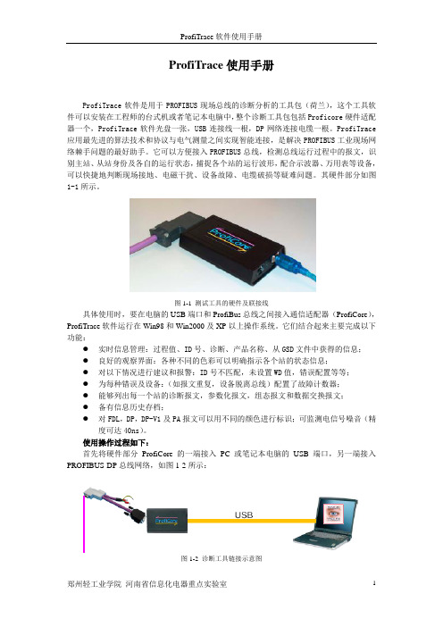
使用操作过程如下:首先将硬件部分ProfiCore的一端接入PC或笔记本电脑的USB端口,另一端接入PROFIBUS-DP总线网络,如图1-2所示:图1-2 诊断工具链接示意图在桌面双击ProfiTrace图标打开软件(如图1-3所示):图1-3 ProfiTrace桌面图标然后需要对其进行初始化,单击下面图标:,用于ProfiTrace对于DP网络进行速率自动匹配以用来捕捉DP网络报文信息。
PROFIBUS现场总线故障诊断方法

PROFIBUS 现场总线故障诊断方法摘要:PROFIBUS是一种应用于工业领域现场总线,由于现场环境复杂,PROFIBUS网络通信不稳定,造成了对生产的影响。
经过PROFIBUS总线排查和分析,认为通讯电缆太长导致信号衰弱,现场模块供电电压压降,电磁干扰,DP通信头阻值过小和接地等原因所致,加装中继器,重新敷设通讯电缆,接地牢固等方法,不仅保证了PROFIBUS网络通信稳定,又可以预防PROFIBUS总线故障。
关键词:PROFIBUS总线,现场模块,网络通信,信号衰弱,电磁干扰一、前言积放链采用了以三菱PLC及其相关模块控制为核心,PROFIBUS DP作为总线通信,双绞线作为通信介质以及现场模块等组成一套控制系统。
本论文主要结合实际情况,将以往发生的各种总线故障诊断进行分析归类,总结出针对积放链总线故障处理方法和预防措施。
二、系统介绍和PROFIBUS总线介绍2.1、系统介绍积放链是由三菱A系列PLC作为控制核心,由QJ71PB92V模块作为等级1主站使用,通过PROFIBUS-DP协议将触摸屏以及现场30个模块进行通讯,以及3个驱动链条装置和若干个电磁阀组成的控制系统。
2.2、PROFIBUS总线介绍PROFIBUS作为业界应用最广泛的现场总线技术,是一种串行现场总线通信技术,是按照ISO/OSI开放系统互连模型层网络模型构建,主要分为DP/FMS/PA几种行规。
FMS行规因为协议层太繁琐,不能适应高速现场总线的需求,实际应用已经很少见到;目前应用最多的是DP和PA行规,在这里主要介绍的是DP行规。
PROFIBUS-DP使用有主站和从站。
PROFIBUS-DP网络理论上最多可有32个主站,整个网络中所有的物流站点可达到127个,主站之间用令牌传递,获得令牌的主站可轮询从站。
网络拓扑是线性总线,两端都带终端电阻,允许一定的短截线和分支(树)存在,通信介质、网络距离、通信站点数取决于信号特性,两个站点之间采用屏蔽双绞线通讯,传输速率在9.6Kbit/s-12Mbit/s。
福富CDMA话单数据跟踪分析系统使用手册V1.0版
福建富士通福富C D M A话单数据跟踪分析系统----用户手册版权所有,© 福建富士通信息软件有限公司目录1.前言 (4)2.系统要求 (4)3.安装说明 (4)3.1安装文件清单 (4)3.2M Y SQL数据库安装和配置步骤说明 (5)3.3M Y SQL的ODBC驱动安装 (16)3.3控件和动态库的安装 (18)3.4数据库初始化 (19)3.5工具文件的复制 (20)4. 使用说明 (20)4.1运行工具 (20)4.2系统参数信息导入 (21)4.3CDT文件导入 (23)4.4CDT基本数据清除 (24)4.5专题分析 (25)4.5.1 疑似单通分析 (25)4.5.2 全网TOPN用户分析 (27)4.5.3 IMSI详细分析 (30)4.5.4 接入覆盖影响分布统计 (34)4.5.5 无线覆盖分析 (36)4.6帮助信息 (44)1.前言CDTAnalyser是CDT二次分析工具,它的主要功能是通过对导入的CDT(Call Detail Trace)数据进行深入分析挖掘,从而正确定位网络问题区域,掌握用户真实感受再现无线环境和通话情形,发现网络潜在的问题。
帮助C网运营商不断的优化现有网络质量,提升客户对C网的使用感受。
为了方便使用,本说明书将对CDTAnalyser工具各功能的安装、使用,以及使用过程中需要注意的地方进行详细的说明。
2.系统要求操作系统:windowsXP内存:2G以上硬盘:剩余空间2G以上数据库:MySQL5.0以上其他软件:excel20033.安装说明3.1 安装文件清单mysql-essential-5.1.39-win32.msi:MySQL安装文件Setup.exe:MySQL ODBC驱动MSCHART注册.exe:必需的控件和动态库安装文件MSDATGRD.OCX:必需的控件和动态库安装文件MSSTDFMT.DLL:必需的控件和动态库安装文件Sql\ AidanceFunction.sql:数据库初始化文件Sql\cdma_1x_basicdata.sql:数据库初始化文件Sql\cdma_1x_errorcause.sql:数据库初始化文件Sql\cmda_1x_basicdata_view.sql:数据库初始化文件Sql\hwdelay.sql:数据库初始化文件Sql\oneway_audio_analysis_tbl.sql:数据库初始化文件Sql\oneway_audio_analysis_view.sql:数据库初始化文件Sql\radiocover_analysis_tbl.sql:数据库初始化文件Sql\radiocover_analysis_view.sql:数据库初始化文件Sql\syspara.sql:数据库初始化文件Sql\TopN_analysis_view.sql:数据库初始化文件Sql\run.bat:数据库初始化文件CDTAnalyser.exe:工具的执行文件output.xls:工具进行数据导出存盘是需要的模板文件3.2 MySQL数据库安装和配置步骤说明1启动MySQL安装向导;打开CDTAnalyser工具安装包下的MYSQL安装文件mysql-essential-5.1.39-win32.msi,双击运行,将出现如下安装向导界面:2执行MySQL安装操作;按“Next”继续后选择安装类型,有“Typical(默认)”、“Complete(完全)”、“Custom (用户自定义)”三个选项,选择“自定义”(Custom)安装,然后点“Next”下一步,出现自定义安装界面我们这里就按照默认的这个路径。
TracePro交互式优化工具使用说明

TracePro交互式优化⼯具使⽤说明1.Introduction1.IntroductionTracePro?Interactive Optimizerhelps users generate and also accomplish the optimization process of the Optical Elements and whole system-quickly and accurately.It provides a convenient and intuitional user interface to create radial free-form optical element(s).While useful for luminaire design,this tool can also be used to optimize LED second optics,reflective optics,projector system,solar concentrator and any other optical system needed optimization.The utility is for use with all TracePro editions and requires the most recent release of TracePro7.0and Microsoft Windows XP or later version.For more information on TracePro,or if you need technical support,please contact Lambda Research Corporation.About Lambda Research CorporationFounded in1992,Lambda Research Corporation is a privately held company based in Littleton,/doc/8b19926bcaaedd3383c4d3ad.html mbda provides optics software and services for government and industry worldwide.The company is an industry pioneer in the areas of stray light analysis,optical system design and analysis,scattering theory,optical testing,process control software and custom software development.Technical SupportIf you are having trouble with TracePro or have questions,please contact your distributor or Lambda Research Corporationdirectly.Technical support is available to customers with current support contracts.Additional information is also available via:the World Wide Web at /doc/8b19926bcaaedd3383c4d3ad.htmlthe user to user e-mail list tracepro-talkthe new version e-mail list tracepro-updatesTo subscribe to one of the e-mail lists,submit a request online at /doc/8b19926bcaaedd3383c4d3ad.html/lists/listinfo.You can call us between the hours of9:00am and5:30p.m.(U.S.Eastern Time)Monday through Friday or reach us by e-mail.Lambda Research Corporation25Porter RoadLittleton MA01460Phone:(978)486-0766Fax:(978)486-0755support@/doc/8b19926bcaaedd3383c4d3ad.html2.Getting Started2.Getting StartedInteractive optimizer offers an intuitive graphical user interface.Its multi-window design makes it easy to initiate a prototype design and monitor the optimization process with the instant simulation data returned from TracePro.This manual generally assumes a working knowledge of Windows.When Interactive Optimizer launched,a MDI window is initiated for starting a new optimization plan.The Interactive Optimizer user interface consists of:Profile editor windowToolbox panelProperty windowExport panelOptimization control panelOptimization logOptions panelBelow you can find instructions for some of the most basic Surface Source Property Generator operation More:Profile editor windowToolbox panelProperty windowExport panelOptimization control panelOptimization logOptions panel2.1Interactive Optimizer InterfaceInteractive Optimizer is a pure graphical user interface application.It helps users generate many kinds of freeform geometry and simulate its optical system performance in TracePro?.Furthermore it manipulates TracePro?to accomplish the optimization through DDE channel.To understand the interfaces of Interactive Optimizer,a simple description about each child windows are necessary,they are:3.Interactive Profile EditorOptical designers always have a lot of brilliant ideas to create optical systems.The optics geometry shape that they want to use in their system it’s not a primitive geometry,like sphere or block.Thus,how to create a desired geometry shape is an important issue.Even some people can’t100%simulate their optical system in TracePro,just because of complicate model creating problem.And here,Interactive Optimizer can help designer create their complicate optical components quickly and accurately.Interactive Optimizer provides Interactive Profile Drawer to easily create geometry.In Drawer,user can use straight line and spline to draw an enclosed loop to represent geometry’s profile.And without limiting the number of node point,the profile can fully matches use’s desire.The finished profile can be directly export to TracePro as a3D solid object.Or this profile can be the initial design of a system optimization process.Furthermore,it provides real-time2D raytrace function to speed up create a better initial design.There are a lot of features,such like drawing profile,raytrace,paste background bitmap and so on,that are included in Interactive Profile Drawer.So,for convenient operation,there is an independent“Toolbox”panel to switch Profile Drawer to different function.More:Interactive Profile Drawer-SegmentInteractive Profile Drawer-ObjectInteractive Profile Drawer-RaysInteractive Profile Drawer-Bitmap3.1Segment ModeAdd Segment/Control PointTo add a segment/control point into the segment,first right-click on the wanted position of the segment and then click on the"Add Segment/Control Pont"command from the pop-up menu.Delete Segment/Control PointRight-click on the wanted segment/control point and then click on the"Delete"command from the pop-up menu.Segment Type SelectionRight-click on the interested segment and then choose the wanted segment type from the pop-up menu. Now there are five segment types provided:Line:Straight line is used to connect the two adjacent segment points.Spline:Spline curve is used to fit the control points between the two adjacent segment points.Sphere:Spherical curve is used to connect the center control point and the two adjacent segment points.Ellipse:Elliptical curve is used to connect the center control point and the two adjacent segment points.Conic:Conic curve is used to fit the control points and the two adjacent segment points.Adjust Object ShapeThe shape of the object can be modified by dragging the segment/control points among the segments. 3.2Object ModeAddRight-click on the editing area to determine the center position height of the new object.Then click on the "New Object"command from the pop-up menu will add a new object into the editor window.MoveSelect the wanted object by first locating the mouse on any of the segments of it.Then move the mouse cursor with the left button depressed will move the selected object.DeleteSelect the wanted object by first locating the mouse on any of the segments of it.Then right-click the mouse and select“Delete Object”from the pop-up menu will delete the selected object.3.3Rays ModeAddTo start tracing a single ray,pressing the mouse left button at the interested start position and then drag the mouse to determine the direction of the emitting ray.Two functions are also provided for generating ray array,i.e., ray fan or ray sequence:Ray fan–First,press and drag the left button to decide the initial ray position and emit direction.Hold on the left buttonand,meanwhile,press the[ctrl]key.Then drag the mouse around to decide the expanding angle of the ray fan.Once done,release the mouse button and the[ctrl]key,and the ray fan will be added into the editor window.Ray sequence-First,press and drag the left button to decide the initial ray position and emit direction.Hold on the left button and,meanwhile,press the[Shift]key.Then drag the mouse to decide the extending range of the ray sequence.Oncedone,release the mouse button and the[shift]key,and the ray sequence will be added into the editor window.Delete RayRight-click on the interested ray and select“Delete Ray”from the pop-up menu will delete the selected ray.Clear all raysRight-click the mouse and select“Clear all rays”from the pop-up menu will delete the whole rays.3.4Bitmap ModeAddTo paste the grabbed picture,right-click on the editing area to determine the center position of the pasted image.Then click on the"Add bitmap from clip board"command from the pop-up menu,the stored picture in the clipboard will be pasted into the editor window. DeleteRight-click on the center point of the pasted bitmap and then click on the“Delete”command from the pop-up menu will delete the pasted bitmap.AdjustThe pasted bitmap can be rotated or scaled by dragging the control points of the bitmap frame.4.ToolboxThe ToolBox Panel is the control panel for users to select the manage mode of the Profile Editor Window.In each manage mode,users can implement different actions to the displayed objects in the model.More:Toolbox-Mode4.1ModeSegWhen Seg mode is selected,users can reshape the object profile by making adjustment to the segment/control point position in the Profile Editor Window.The way how the segment/control points are connected will base on the curve type selection of each segment.ObjWhen Obj mode is selected,users can select to add,delete,or move an arbitrary object in the model.RaysWhen Rays mode is selected,the raytrace function is enabled,and this helps give a quick check to the designmodel.Show RaysWhen Show Rays icon is checked,the traced rays will be instantly shown in the Profile Editor Window.BitmapWhen Bitmap mode is selected,users can paste,modify,or delete the grabbed image in the Profile Editor Window.Show BitmapWhen Show Bitmap icon is checked,the pasted picture will be shown as the background image in the Profile Editor Window.Opacity TunnerThrough the Opacity Tuner,users can directly tune the opacity of the pasted bitmap.Unit SelectorUsers can select the unit of the editor window to be mm,cm,or m.5.PropertyThe Property Editor allows users define the environment and object property in the model.More:Property Editor-General TabProperty Editor-Object Tab5.1General TabThe refractive index data are shown in the Refractive Indices /doc/8b19926bcaaedd3383c4d3ad.html ers can set the refractive index value of each item from the table.5.2Object TabThe detailed property information of an object will be shown in this /doc/8b19926bcaaedd3383c4d3ad.html ers can select to modify the item they want and the corresponding will be highlighted in the Profile Editor Window.6.ExportTo open the Export Panel,click on menu button:"Export".To generate geometry model and apply properties,use Export function to create a complete model including its optics properties in TracePro.Through DDE link,objects with the designated surface profiles can be directly added into the model window of TracePro.The creation mode and the applied property of each object can be checked and modified in the Export PanelMore:Export Optical Element(s)Creation Mode6.1Optical Element(s)This window generates optics object(s)in TracePro.Each object's geometry profile bases on”Editor Window”.And then,bydifferent“Creation mode”,3D shape could be“Radial Symmetry”,“Biaxial”andproperty.Export7.OptimizationThere are4regions in the optimization window.They are“Saving Optimization Log Options”,“Optimization Variables List”,“Optical Element Export Options”and“Definitions of Optimization Operands”.All parameters in this window will determine whether Interactive Optimization Utility links TracePro successfully and how to accomplishthis optimization.While everything is ready,click"Start"button to begin optimization.More:Optimization-OptionsOptimization-VariablesOptimization-OperandsOptimization-Objects7.1OptionsInteractive Optimization Utility uses DDE(Dynamic Data Exchange),a Windows protocol to share information with TracePro.To establish a full optimization,utility exports geometry to current document, commands that TracePro apply properties to exported object(s),and then initiates raytrace and saves simulation result.The whole optimization process would be saved.Thus,the file path and log file name have to be defined in advance.7.2VariablesAll variables will be listed in this panel.It’s just a simple viewer to monitor all variables in an easy way.We suggest not changing any value in this panel.That may cause some problems.The ideal way to modify variable-related values is through the Property window's Object Tab.Additional VariableIn some complicated case,we need some more advanced optimization skill to optimize our/doc/8b19926bcaaedd3383c4d3ad.html ually advanced optimization skill goes along with using After-scheme.To insert a new user-defined variable,first step is right click on this panel,and insert a user-defined variable.After setting its initial value,upperand lower limits, this variable’s name would be recognized in After-scheme.This new variable can be used to be one parameter of all commands in After-scheme.7.3OperandsAfter you have initiated the design of geometry shape,you need to set up the merit functions for you design system.For the following optimization process,it will take all operands as references and considering individual weight to evaluate the error value of each run.There are five different kinds of operands can be used.They are Flux,CIExy,CIEu’v’,Irradiance Profile and Candela Profile.Besides,each operand has different way to set up.Operand Type-FluxThe calculation of flux operand’s error value bases on the difference value between the target value and total flux of selection area on the observation plane.Operand Type-CIE u'v'&CIE xyThe calculation of CIE operand’s error value bases on the color difference on CIE map between the target color and the average color on selected region on observation plane.Operand Type-Irradiance ProfileThe calculation of Irr Profile operand’s error value bases on the irradiance/illumunance profile similarity between the target profile and the profile gotten from observation plane.。
- 1、下载文档前请自行甄别文档内容的完整性,平台不提供额外的编辑、内容补充、找答案等附加服务。
- 2、"仅部分预览"的文档,不可在线预览部分如存在完整性等问题,可反馈申请退款(可完整预览的文档不适用该条件!)。
- 3、如文档侵犯您的权益,请联系客服反馈,我们会尽快为您处理(人工客服工作时间:9:00-18:30)。
ProfiTrace使用手册
ProfiTrace软件是用于PROFIBUS现场总线的诊断分析的工具包(荷兰),这个工具软件可以安装在工程师的台式机或者笔记本电脑中,整个诊断工具包包括Proficore硬件适配器一个,ProfiTrace软件光盘一张,USB连接线一根,DP网络连接电缆一根。
ProfiTrace 应用最先进的算法技术和协议与电气测量之间实现智能连接,是解决PROFIBUS工业现场网络棘手问题的最好助手。
它可以方便接入PROFIBUS总线,检测总线运行过程中的报文,识别主站、从站身份及各自的运行状态,捕捉各个站的运行波形,配合示波器、万用表等设备,可以快捷地判断现场接地、电磁干扰、设备故障、电缆破损等疑难问题。
其硬件部分如图1-1所示。
图1-1 测试工具的硬件及联接线
具体使用时,要在电脑的USB端口和ProfiBus总线之间接入通信适配器(ProfiCore),ProfiTrace软件运行在Win98和Win2000及XP以上操作系统。
它们结合起来主要完成以下功能:
●实时信息管理:过程值、ID号、诊断、产品名称、从GSD文件中获得的信息;
●良好的观察界面:各种不同的色彩可以明确指示各个站的状态信息;
●对以下情况进行建议和报警:ID号不匹配,未设置WD值,错误配置等等;
●为每种错误及设备:(如报文重复,设备脱离总线)配置了故障计数器;
●能够列出每一个站的诊断报文,参数化报文,组态报文和数据交换报文;
●备有信息历史存档;
●对FDL,DP,DP-V1及PA报文可以用不同的颜色进行标识;可监测电信号噪音(精
度可达40ns)。
使用操作过程如下:
首先将硬件部分ProfiCore的一端接入PC或笔记本电脑的USB端口,另一端接入PROFIBUS-DP总线网络,如图1-2所示:
图1-2 诊断工具链接示意图
在桌面双击ProfiTrace图标打开软件(如图1-3所示):
图1-3 ProfiTrace桌面图标
然后需要对其进行初始化,单击下面图标:,用于ProfiTrace对于DP网络进行速率自动匹配以用来捕捉DP网络报文信息。
检测完成总线波特率后ProfiTrace会自动装载当前系统的组态信息,显示当前站点情况,如图1-4所示:
图1-4 站点信息
(注意:并非所有的情况下,初始化之后,都会显示从站的ID号,只有在DP网络进行初始化或者从站出现故障的时候,才会显示其ID号,正常运行条件下,显示如图1-5)
图1-5 站点信息
然后开始进行报文采集,点击下面按钮:
注意在开始进行报文采集的之前最好根据自己的需求对采集的信息进行相应的选择,以确保满足用户的需求,不然会采集不到报文信息,或者采集过多的报文信息。
对报文信息进行设置点击,在如图1-6所示的对话框中进行设置,并使能触发,如图1-7所示。
图1-6 触发设置
图1-7 使能选择
选中Enabled,点击Setup trigger如图1-8进行设置
图1-8 报文信息采集设置
根据用户对于报文信息量的需求,选择合适的时间之后(大约5秒钟之后),点击下面按钮结束报文采集过程:
此时可以点击选项卡查看刚刚所记录到的报文:
诊断报文:
参数设置报文:
组态报文:
数据交换报文:
以及全局控制报文:
另外对于所显示的报文格式也可以进行设置,用户可以设置显示感兴趣的报文信息,而屏蔽掉不关心的报文信息。
对报文信息显示格式进行设置点击菜单栏Setting选择Preferences,如图1-7所示,选项设置如图1-8所示。
图1-7 报文参数显示选择
图1-8 报文参数显示设置
如果需要在记录的报文中快速的查看某一类的报文可是使用搜索功能,这样非常方便同类报文的观察,如图1-9对搜索进行设置,搜索上一个或者搜索下一个。
图1-9 报文搜索功能。