宝马5系E60手册技术资料:mfp-brk-e60-rohhk-basic-update_en
宝马(E60 M5)整车技术培训手册-1
资料来源:国内最大的维修资料库 精通维修下载站 :/
资料来源:国内最大的维修资料库 精通维修下载站 :/
资料来源:国内最大的维修资料库 精通维修下载站 :/
资料来源:国内最大的维修资料库 精通维修下载站 :/
资料来源:国内最大的维修库 精通维修下载站 :/
资料来源:国内最大的维修资料库 精通维修下载站 :/
资料来源:国内最大的维修资料库 精通维修下载站 :/
资料来源:国内最大的维修资料库 精通维修下载站 :/
资料来源:国内最大的维修资料库 精通维修下载站 :/
资料来源:国内最大的维修资料库 精通维修下载站 :/
资料来源:国内最大的维修资料库 精通维修下载站 :/
资料来源:国内最大的维修资料库 精通维修下载站 :/
资料来源:国内最大的维修资料库 精通维修下载站 :/
资料来源:国内最大的维修资料库 精通维修下载站 :/
资料来源:国内最大的维修资料库 精通维修下载站 :/
资料来源:国内最大的维修资料库 精通维修下载站 :/
资料来源:国内最大的维修资料库 精通维修下载站 :/
资料来源:国内最大的维修资料库 精通维修下载站 :/
资料来源:国内最大的维修资料库 精通维修下载站 :/
资料来源:国内最大的维修资料库 精通维修下载站 :/
资料来源:国内最大的维修资料库 精通维修下载站 :/
资料来源:国内最大的维修资料库 精通维修下载站 :/
资料来源:国内最大的维修资料库 精通维修下载站 :/
资料来源:国内最大的维修资料库 精通维修下载站 :/
资料来源:国内最大的维修资料库 精通维修下载站 :/
资料来源:国内最大的维修资料库 精通维修下载站 :/
资料来源:国内最大的维修资料库 精通维修下载站 :/
宝马4S店维修培训手册:E60 传动系 变速箱 售后培训
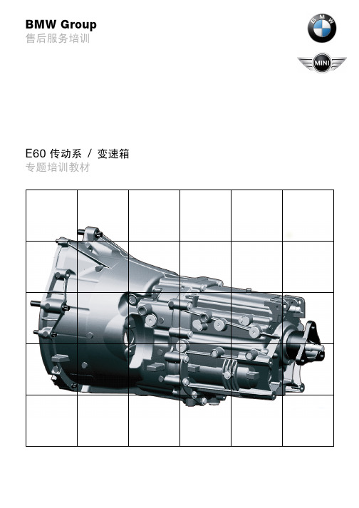
BMW Group售后服务培训E60传动系/变速箱专题培训教材提示本培训手册中包含的信息仅用于接受售后服务培训的人员。
技术数据的更改 / 补充摘自“BMW 售后服务”的有关信息。
© 2003 BMW AG慕尼黑,德国。
没有宝马汽车公司的书面授权,任何人不得再版、复制及摘录VS-12/Vs-42 MFP-HGK-BRK-0300_update目录页码第一章引言1 - 手动变速箱3-自动换档控制的手动变速箱(SMG)3- 自动变速箱3- 传动轴,后桥差速器,输出轴3手动变速箱4- 技术数据5- H 变速箱的特点5- H 变速箱发动机侧的特点10-维修说明12自动换档控制的手动变速箱(SMG)13- 系统一览14- 部件22- 系统功能25- 国家规格27-维修说明28自动变速箱30- 系统一览32- 部件38- 系统功能43- 维修说明46传动轴,后桥差速器,输出轴50- 系统一览50- 部件51-维修说明60引言在 E60 中可分别使用 2 种手动变速箱、自动换档控制的手动变速箱(SMG )和自动变速箱系列以及 2 种后桥差速器(取决于发动机 - 变速箱组合)系列。
组合系列和选择装备(SA )变速箱名称手动变速箱、自动换档控制的手动变速箱(SMG )和自动变速箱按照 BMW 集团标准(GS )90007 进行命名。
后桥差速器例外。
它命名为 188K 或者 215K 。
发动机系列自动变速箱选择装备自动换档控制的手动变速箱(SMG )选择装备后桥差速器M54B22GS6-37BZ GA6HP19Z H-SMG 188K M54B30GS6-37BZ GA6HP19Z H-SMG 188K N62B44GS6-53BZ GA6HP26Z G-SMG 215K M57D30TUGS6-53DZGA6HP26Z---215K动态行驶控制(FDC)动态行驶控制(FDC)的功能与自动换档控制的手动变速箱一起批量生产安装。
BMW5系-E60普通车辆电器-2002

说明 灯光模块 晴雨 / 行车灯传感器 活动天窗模块 活动天窗开关 自动恒温空调 IHKA 带加热装置的喷嘴 带加热装置的喷嘴 便捷进入及起动系统 CAS byteflight (BMW 安全总线系统) 车身 CAN LIN 总线
-4-
E60 普通车辆电气系统
车窗升降机 FH
车门模块以非中央方式对前部车窗升降机进行控制。 车身标准模块 KBM 控制后部车窗升降机。 便捷进入及起动系统控制单元作为主控单元控制: - 通过无线电遥控钥匙的操作 - 便捷功能 - 中控锁接口 - 儿童保护装置 - 不同国家规格的设置权限 象其它车型一样,车窗升降机可通过驾驶员侧车门开关组 SBFA 和其它车门中 的开关操作。
-1-
- 系统一览
E60 普通车辆电气系统
KT-11548
图 1:
E60 普通车辆电气系统一览
-2-
E60 普通车辆电气系统
序号 1 2 3 4 5 6 7 8
9 10 11 12 13 14 15
说明 驾驶员外后视镜 驾驶员侧车门锁芯 驾驶员侧前部中控锁 驾驶员侧前部车窗升降马达 驾驶员侧开关组 环境照明 驾驶员下车灯 驾驶员侧车门模块 TMFA
-5-
- 系统一览
E60 普通车辆电气系统
KT-10933
图 2:
车窗升降机
-6-
E60 普通车辆电气系统
序号 1 2 3 4 5 6 7 8 9 10
说明 驾驶员侧车门模块 TMFA 驾驶员侧车门开关组 驾驶员侧前车门车门触头 驾驶员侧前车门车窗升降机 安全和网关模块 SGM 前乘客侧车门模块 TMBF 前乘客侧前部车窗升降马达开关 前乘客侧前车门车门触头 前乘客侧前车门车窗升降马达 便捷进入及起动系统 CAS
MFP-BRK-E65-KAROSSERIE-GFZ-zh
所有其它灯泡 ( 转向信号灯和远光灯 ) 可以在不拆下大灯的情况下更换
用于远光灯和近光灯高度调整及侧向调整的调整螺钉可通过开口够到 外侧的调整螺钉 (1) 用于两个车灯的侧向调整 内侧的调整螺钉 (2) 用于 远光灯和近光灯的高度调整
- 13 -
E65 整车车身
图 12 带调整螺钉的大灯
KT-8315
图 1 前部斜视图
KT-8629
-1-
E65 整车车身
图 2 后部斜视图
KT-8630
- 设计
E65 在外观开发设计方面也实现了一个飞跃
全新的指导性设计理念散发着动感和创新的激情 " 棱角 " 与 " 圆弧 " 之间过渡流畅 类似双门轿跑车的车顶线条简洁明 快 另外 结构新颖的大灯和车尾将引领未来车型潮流 车尾最新的强光灯光技术使车辆表现更突出 然而 在该系列车型上仍然象上一代车型一样保留了 BMW 典型的特 征 例如水箱面罩
-9-
E65 整车车身
图 8 发动机室
索引 1 2 3 4
说明 底盘号码 控制单元 / 保险丝的安装位置 微尘滤清器 白车身号码
KT-8223
- 10 -
- 大灯
E65 整车车身
图 9 前大灯
索引 1 2 3 4 5
说明 转向信号灯 停车灯 ( 卤素灯 ) 近光灯 选装双氙气灯时的附加远光灯 选装双氙气灯时的停车灯 远光灯
- 车窗玻璃清洗装置 (SRA)
在 E65 上首次使用了臂管组合技术 喷嘴集成在刮水器中 因此不必调整喷嘴 车窗玻璃清洗装置和大灯清洗装置的储液罐合成为一个储液罐 它位于左轮罩下 由一个朝向车轮的盖板保护着 可通过发动机室内的一个加注管接头为这个容量为 6.5 升的储液罐添加 清洗液 刮水器有一个便于装配 / 拆卸刮水片的折起位置 为了将刮水器移至这个 位置 必须在总线端 Kl. R 已关闭的情况下按住刮水器开关至少 3 秒钟
宝马4S店维修培训手册:E60 高级安全电子设备 售后培训
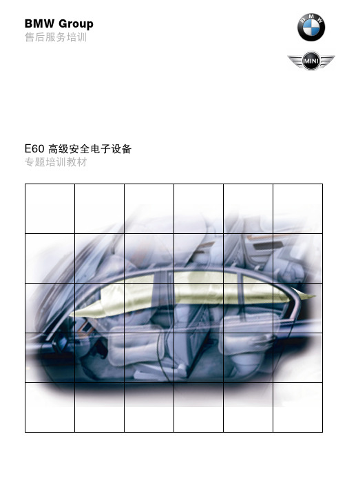
BMW Group售后服务培训E60高级安全电子设备专题培训教材提示本培训手册中包含的信息仅用于接受 BMW 售后服务培训课程的人员。
技术数据的更改/补充摘自“技术售后服务”的有关信息。
© 2003 BMW AG慕尼黑,德国。
没有宝马汽车公司的书面授权,任何人不得再版、复制及摘录VS-12/Vs-42 MFP-HGK-BRK-1000_update目录页码第一章高级安全电子设备 ASE1引言1- 高级安全电子设备中的新技术2- 系统优点3系统一览4- 总线一览4- 系统一览欧规车6- 系统电路图(欧规车)8部件(欧规车)10- byteflight12- 安全和网关模块 SGM13- 左侧 / 右侧 B 柱卫星式控制单元 SBSL/SBSR18- 驾驶员侧 / 前乘客侧车门模块 TMFA/TMBF20- 车辆中央卫星式控制单元 SFZ24- 转向柱开关中心 SZL25- 安全带锁扣开关28- 座位占用识别装置29- 蓄电池导线诊断30- 驾驶员前部安全气囊34- 前乘客前部安全气囊35- 高级 ITS(头部安全气囊)36- 侧面安全气囊38- 安全带拉紧装置39- 主动式头枕41- 安全蓄电池接线柱 SBK43系统功能44- 触发规则44- 欧规车紧急呼叫50美规车52- 引言52美规车系统一览53部件57维护说明65高级安全电子设备 ASE引言高级安全电子设备 ASE 作为一种新型被动安全系统,用于 E60 及该系列的其他车型。
ASE 取代了迄今使用的 MRS 系统(多重乘员保护系统)。
该系统与 E65/E66 车型中的智能型全面安全系统 ISIS 采用了相同的技术。
ASE 是为满足 E60 车型的要求而专门设计的。
- 高级安全电子设备中的新技术与 E65/66 车型相同,在 E60 车型中使用了新的光缆技术byteflight(BMW 安全总线系统)。
ASE 系统由一个主控制单元、安全和网关模块 SGM 和多个卫星式控制单元组成。
E60系统 部分参数说明

E60系统·部分参数说明◆基本规格参数#1001 (PR) SYS_ON (系统有效设定)➢参考值:1、2、PLC的值分别为1、0、0➢含义:通过I/O设定NC轴和PLC轴的有无➢范围:0:无 1:有#1002 (PR) axisno (轴数)➢参考值:1、2、PLC值分别为3、0、0➢含义:设定NC轴及PLC轴的轴数➢范围:0~4#1013 axname (轴名)➢参考值:1、2、3值分别为X、Z、Y➢含义:使用字母指定各轴的轴名地址➢范围:X、Y、Z、U、V、W、A、B、C等轴地址#1014 incax (增量指令轴名)➢参考值:1、2、3值分别为U、W、V➢含义:当指定程序移动量的绝对/增量时,使用字母指定增量指令的轴名地址➢范围:X、Y、Z、U、V、W、A、B、C等轴地址#1018 (PR) ccw (电机ccw)➢参考值:1、2、3的值均为1➢含义:指定相对于指令方向的电机旋转方向➢范围:0:顺时针方向旋转 1:逆时针方向旋转#1022 (PR) axname2 (第2轴名称)➢参考值:1、2、3的值分别为X、Z、Y➢含义:使用2个字符设定画面上显示的轴名称➢范围:A~Z及1~9,2位(输入0则清除)#1025 I_plane (起始平面选择)➢参考值:值为0➢含义:指定将接通电源时及复位时的平面选择设定为哪个平面➢范围:0、1:X-Y平面 2:Z-X平面 3:Y-Z平面#1026 base_I (基本轴I)#1027 base_J (基本轴J)#1028 base_K (基本轴K)➢参考值:base_I、_J、_K依次指定为X、Y、Z➢含义:指定构成平面的基本轴的地址➢范围:X、Y、Z等控制轴地址#1037 cmdtyp (指令类型)➢参考值:3➢含义:指定程序的G代码体系与补偿类型;cmdtyp G代码体系补偿类型3 系列2(L用)类型C(对于一个补偿编号,设置形状、磨损两种补偿量)➢范围:1~8#1043 lang (显示语言选择)➢参考值:22➢含义:指定显示语言 22:汉语(简体字)➢范围:0~3、11~22#1073 I_Absm (起始绝对值)➢参考值:1➢含义:指定接通电源时及复位时的绝对值/增量值模式➢范围:0:增量值指令模式 1:绝对值指令模式#1076 AbsInc (ABS/INC 地址)➢参考值:1➢含义:对于同一轴,可通过分别使用绝对值用/增量值用的两个地址,进行绝对值/ 增量值的指令➢范围:0:绝对/增量根据G指令决定 1:绝对/增量根据地址代码决定#1084 RadErr (圆弧误差)➢参考值:0.1➢含义:在圆弧指令中,指定终点与中心坐标存在偏差时允许误差范围➢范围:0~1,000(mm)#1155 DOOR_m (系统共用门互锁Ⅱ用信号输入设备1)➢参考值:100➢含义:当不使用门互锁Ⅱ的固定设备编号时,设定为“100”➢范围:000~100(16进制)#1156 DOOR_s (系统共用门互锁Ⅱ用信号输入设备2)➢参考值:100➢含义:当不使用门互锁Ⅱ的固定设备编号时,设定为“100”➢范围:000~100(16进制)#1174 skip_F (G31跳跃速度)➢参考值:100➢含义:指定G31(跳跃)指令时,程序中没有F指令时的进给速度➢范围:0~999999(mm/min)#1185 spd_F1 (F1 数位进给速度)#1186 F2 (F2 数位进给速度)#1187 F3 (F3 数位进给速度)#1188 F4 (F4数位进给速度)#1189 F5 (F5 数位进给速度)➢参考值:spd_F1、F2、F3、F4、F5依次指定为100、200、300、400、500 ➢含义:指定F n时的速度(mm/min)➢范围:1~60000(mm/min)#1240 (PR) set12 (bit0) (手轮输入脉冲切换)➢参考值:0➢含义:选择手轮的输入脉冲0:手轮支持100脉冲(+12V电源)1:手轮支持400脉冲(+5V电源)➢范围:0/1#1534 SnG44.1 (G44.1指令时的主轴编号)➢参考值:1➢含义:设定G44.1指令时的选择主轴编号➢范围:0:第2主轴 1:第1主轴 2:第2主轴◆轴规格参数#2001 rapid (快速进给速度)➢参考值:X、Z、Y的值均为10000➢含义:设定各轴的快速进给速度,其最大值取决于机械系统➢范围:1~999999(mm/min)#2002 clamp (切削进给负载速度)➢参考值:X、Z、Y的值均为4000➢含义:定义各轴的切削进给最高速度➢范围:1~999999(mm/min)#2003 (PR) smgst (加减速模式)➢参考值:X、Z、Y的值均为0021➢含义:指定加减速控制模式 2:bit7~4,0010,类型:一次延迟(切削进给)1:bit3~0,0001,类型:直线加、减速(快速进给)➢范围:以HEX设定#2004 G0tL (G0时间常数(线性))➢参考值:X、Z、Y的值均为100➢含义:设定快速进给加减速中,直线控制的加减速时间常数➢范围:1~4000(ms)#2005 G0t1 (G0时间常数(1次延迟))➢参考值:X、Z、Y的值均为100➢含义:设定快速进给加减速中1次延迟时间常数➢范围:1~5000(ms)#2007 G1tL (G1时间常数(线性))➢参考值:X、Z、Y的值均为30➢含义:设定切削进给加减速中的直线控制时间常数➢范围:1~4000(ms)#2008 G1t1 (G1时间常数(1次延迟))➢参考值:X、Z、Y的值均为30➢含义:设定切削进给加减速中的1次延迟时间常数➢范围:1~5000(ms)#2011 G0back (G0齿隙)➢参考值:X、Z、Y的值分别为0、120、0➢含义:设定快速进给模式下的移动指令或手动模式中,当方向翻转时进行补偿的齿隙量➢范围:-32768~32767#2012 G1back (G1齿隙)➢参考值:X、Z、Y的值分别为0、120、0➢含义:设定切削进给模式中执行了移动指令时,对方向翻转进行补偿的齿隙量➢范围:-32768~32767#2013 OT- (软件限制I-)#2014 OT+ (软件限制I+)➢参考值:X、Z、Y的设定值以实际值为准➢备注:当回零点完成以后,该设定值都要重新输入➢含义:设定以基本机械坐标的零点为基点的软件限位区域。
汽修资料--宝马5系-E60整车车身

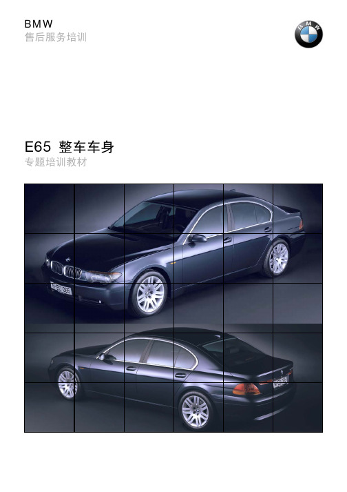
BMW Group售后服务培训E60整车车身专题培训教材For Evaluation Only.Copyright (c) by Foxit Software Company, 2004Edited by Foxit PDF Editor提示本培训手册中包含的信息仅用于接受 BMW 售后服务培训课程的人员。
技术数据的更改/补充请查阅“技术售后服务”中的相应信息。
© 2002 BMW AG慕尼黑,德国。
没有宝马汽车公司的书面授权,任何人不得再版、复制及摘录VS-42 MFP-HGK-BRK-E60_0220目录页码第一章E60 整车车身1引言1前部车身部件5- 车前盖5- 前部侧围5- 发动机室6- 大灯7- 前雾灯8- 前保险杠9- 前围总成10- 挡风玻璃11- 玻璃清洗装置12- 外后视镜13- 嵌条、车门槛盖板14- 前车门15- 车内控制单元的安装位置17- 仪表板22- 中央控制台24- 前座椅26- 后座椅30- 安全气囊32尾部车身部件32- 后侧围32- 后行李箱盖32- 后窗玻璃34- 行李箱35- 行李箱内控制单元的安装位置36- 尾灯39- 后保险杠41活动天窗42车辆底部44E60 整车车身引言2003 年上半年 E60 接替了 E39 开始在 Dingolfing 的工厂投产。
E60 是传统 5 系轿车的进一步发展。
(E12 - E28 - E34 - E39 - E60)图 1: E60 前视图车型 E60从 2003 年 9 月起 525i 和 545i 将投放市场。
520i530i530dKT-11012图 2: E60 侧面尺寸图 3: 高度/宽度尺寸图mm E60E39差值长度48414775+ 66宽度18461800+ 46高度14691435+ 34KT-11013KT -11142图 4: 长度尺寸图重量虽然 E60 比 E39 更长、更宽且更高,但是其全装备重量却降低了约 36kg 。
BMW E60(宝马5系)白车身结构解析

图7 车身A柱内柱
复合相钢(例如,D680C)(英文缩写为CP钢)
这种钢材制造的结构件要具有非常高的强度,在碰撞时要接受很高能量。这种钢是 热轧细晶粒钢。由于合金内的一些元素和使用特殊冶炼方法在这种钢内具有非常精 细的微晶结构。这种结构的成分是铁素体,马丁体和贝氏体。内部很高含量的马丁 体处于最细微的离析状态。 CP钢的特殊的特点在冷强化时还附加有BH钢的功能。但和普通的BH钢不一样的是, 有这种特殊功能更提高了成形能力。DP钢和TRIP钢同样有这种功能。 CP钢的屈服限是680 -720 N/mm2 最大抗拉强度是1150 N/mm2 ,破断延伸率A80 是 10%。 这种钢的可焊性仅仅是有条件的局限使用气体保护焊和电阻焊的进行焊接。在焊接 的时候在受热区和焊接的地方都会出现淬火现象。把这种钢和其他高强度的钢混合 焊接是不合适的。使用在铜基钎焊的方法,例如MIG钎焊不适合于这种钢。 在E65 车身上,发动机支撑架后加强板采用了这种钢。另外E65B柱加强件也使用 D680C(CP-800)钢材。 马丁体金相钢(例如,D900MS) 对于要求接收很高碰撞能量而且变形很小的结构件使用这种钢,缩写称为MS 钢。 和上面讲的CP钢一样,这种MS钢也具有精细的金相组织。通过马丁体和铁素体成 分的合适配比可获得非常高的强度。这种钢在加大变形量的时候还有烘烤硬化钢的 效应。这种钢的屈服限是750 -1100 N/mm2 , 最大抗拉强度是1400 N/mm2 ,破断 延伸率A80是 5%。 MS 钢制成的结构件大多是用于螺栓固定的构件,在损坏时必须全套更换。在E60 车身上这种钢用来制造车门内侧防撞的加强件。
图4 C柱的加强件
烘烤硬化BH钢(例如,H22பைடு நூலகம்B)
很难成形的构件,在制造过程中还应该能够提高强度的时候就常常使用这种BH型钢 材。除了在冷作过程中提高强度以外,这种钢料在车身通过油漆的烘干炉的流程里 面,在20分钟和170度的温度下,可以提高强度大约40 N/mm2。 通过在合金成分内加上磷以及使碳成分老化来实施这种效果。BH钢本身的屈服限是 180 - 300 N/mm2,,最大抗拉强度是500 N/mm2,A80拉伸延伸率为30%。 BH钢在使用气体保护焊和电阻焊的焊接设备时可以实施良好的焊接。 这种钢的典型使用地方是在结构件上,例如在顶棚弓条,这个件必须要有高强度, 但不易成形制造。还有就是外表面板,例如车门外表面板。这种件尽管有高的成形 率,还要有非常好的表明状况和抗变形的强度,这都可以使用BH钢制造。
- 1、下载文档前请自行甄别文档内容的完整性,平台不提供额外的编辑、内容补充、找答案等附加服务。
- 2、"仅部分预览"的文档,不可在线预览部分如存在完整性等问题,可反馈申请退款(可完整预览的文档不适用该条件!)。
- 3、如文档侵犯您的权益,请联系客服反馈,我们会尽快为您处理(人工客服工作时间:9:00-18:30)。
BMW Service( %RG\VKHOO r%DVLF 3DUWLFLSDQW0DQXDONOTEThe information contained in this participant manual is intended for participants of the Aftersales Training.Refer to the relevant "BMW Service" information for any changes/ supplements to the Technical Data.© 2003 BMW AGMünchen, Germany. Reprints of this manual or its partsrequire the written approval of BMW AG, MünchenVS-12/Vs-42 MFP-HGK-BRK-0210_updateContentsPage Introduction1Bodyshell2Joining techniques3- Side panel, front4Weight-reduced aluminium front end GRAV7- Front wheel arch10- Engine support16- Bulkhead20- Welds for EMC24Side frame and roof26Substructure34Rear end38Crash characteristics40IntroductionIn recent years all automobile manufacturers have been increasingly faced with the problem of spiralling weight in today's motor vehicles.In view of constantly increasing engine performance,both the chassis and the body must absorb and transmit ever higher forces.In addition, cars and their interior are generally larger. The reason for this development is that the vehicle size is based on the95%man.The 95% man is derived from the average height of the population. This means only 5% of the population exceed the size of the 95% man. Furthermore,in the past few decades comfort demands have increased continuously resulting in ever more comfort systems either fitted as standard or available as optional equipment.All these factors have lead to an increase in vehicle weight.The objective during the development of the E60 was to stop or even reverse this trend.Consequently, the E60 is the first vehicle to feature a mixed aluminium-steel construction. The front end of the vehicle is made of aluminium with a steel passenger cell and rear end.Thanks to this mixed construction and the use of high strength steels, the body weight was reduced to 255kg (not including doors, bonnet, boot lid and flaps) while weight distribution was substantially improved.BodyshellKT-11776Fig. 1:Bodyshell (yellow = steel, blue = aluminium)Body rigidityJoining techniquesIn E60 series production, the following joining methods are used in the steel section of the body:-MAG welding-MIG braze-welding-Laser welding-Spot-weld bonding-BorderingStatic rigidity, bodyshellValues Framework (carcass)(not including doors, bonnet, rear lid, flaps, front end, front sidepanels)255kg Flexion 1 tunnel6500N/mm Flexion 1 sill7500N/mm Flexion 2 rear centre1900N/mm Flexion 2 rear frame side member1000N/mm T orsion 118500Nm/ºT orsion 217000Nm/ºT ransverse flexion 5500N/mm Dynamic rigidity, overall vehicleValues Flexion 126Hz T orsion 129Hz T orsion 237.5HzPunch-rivetting in connection with bonding processes is mainly used in the aluminium section of the body and for the transition from steel toaluminium.For reasons of electromagnetic compatibility, MIG welds are also used in the aluminium front end. Beading as well as upset joining methods are additionally used for the aluminium outer skin panels.- Side panel, frontThe front side panel is made from aluminium and is produced from2 parts.KT-11786Fig. 2:Front side panelIndex Explanation1Side panel connection2Side panelAn additional screw mounting point is arranged in the upper area of the side panel to the A-pillar. This fastening point is necessary as the side panel extends far upward at this point.Bonnet hinge mountingThe bonnet hinge is uncoupled from the side panel.As a result,no disassembly work needs to be carried out on the bonnet when removing the side panel.KT-11791Fig. 3:Layout in area of bonnet hingeIndex Explanation1Bonnet hinge mountingSide panel fasteningKT-11789Fig. 4:Side panel fasteningIndex Explanation1Special washer for studs2Fastening holes for wheel well shell3C-clipsWeight-reduced aluminium front end GRAV The GRAV is a constituent part of the E60 body. Advantages of the GRAV:-Weight reduction in front end-Optimization of axle load distribution and vehicle handling -Reduced mass increases overall driving comfort-Reduced exhaust emissionsKT-11777Fig. 5:GRAVIndex Explanation1Spring support2Engine support3Bulkhead carrier support 4Outer connection5Bulkhead cross member 6Bulkhead7Inner A-pillar- Front wheel archKT-11822Fig. 6:Exploded view of wheel well (blue = aluminium-magnesium alloy; light-brown = cast aluminium alloy; purple = micro-alloyed steel)Index Explanation Material Elongation limit1Front end support panel Al Mg 3.5 Mn140N/mm2 2Closing plate, front end support panel Al Mg 3.5 Mn140N/mm2 3Closing plate, side panel carrier support Al Mg 3.5 Mn140N/mm2 4Spring support G Al Mg 5 Si 2 Mn5A-pillar extension Al Mg 3.5 Mn140N/mm2 6Extension, side panel carrier support Micro-alloyed steel420N/mm2 7Side carcass connection Micro-alloyed steel420N/mm2 8Extension, side panel carrier support,rearMicro-alloyed steel420N/mm2 9Steel adapter, side panel carrier support Micro-alloyed steel420N/mm2 10Closing plate, side panel carrier support Al Mg 3.5 Mn140N/mm2 11Side panel carrier support, bottom Al Mg 3.5 Mn140N/mm2 12Side panel carrier support Al Mg 3.5 Mn140N/mm2Spring supportKT-11834Fig. 7:Spring supportIndex Explanation1Gate (sprue)Note:Despite the high percentage elongation at fracture in the upper area of the spring support, a maximum 500g hammer should be used whenpunching in the vehicle identification number in order not to damagethe grain structure of the casting.The reason for this is that the top area of the spring support has a higher percentage elongation after fracture.The spring support should be replaced if, after an accident, it can beseen that it was subjected to very high forces. The spring supportshould also be replaced even if no damage is visible.The spring support must be replaced if, for example, after an accident, the outer edge of the spring support has left an impression in the side panel. The forces involved may have caused microcracks to form that are not yet visible with the naked eye.Spring strut towerKT-11820Fig. 8:4-part wheel archIndex Explanation1Rear wheel arch, rear inner half2Spring strut tower3Rear wheel arch, front inner half4Bottom section of spring strut towerInner A-pillarKT-11823Fig. 9:Inner A-pillar (blue = aluminium-magnesium alloy; yellow = TRIP steel;purple = micro-alloyed steel, brown = BH steel)Index Explanation Material Elongation limit1Bulkhead cross member Al Mg 3.5 Mn140N/mm2 2Cross member cover BH steel300N/mm2 3Inner A-pillar TRIP steel500N/mm2 4A-pillar reinforcement, bottom BH steel350N/mm2 5Bottom stiffener plate, A-pillar Micro-alloyed steel500N/mm2 6T op stiffener plate, A-pillar Micro-alloyed steel500N/mm2 7Mounting bracket, front BH steel300N/mm2 8Sill extension Micro-alloyed steel500N/mm2 9Sill extension support BH steel300N/mm2 10Connection reinforcement, outer BH steel300N/mm2 11Outer connection BH steel300N/mm2 12Connection stiffener plate, outer BH steel300N/mm2- Engine supportFig. 10:Exploded view of E60 engine support (green = aluminium-magnesium-silicon alloy;blue=aluminium-magnesium alloy;violet=aluminium crash alloy;light-brown=castaluminium alloy; yellow = TRIP steel; purple = micro-alloyed steel; brown = BH steel)Index Explanation Material Elongation limit1Bush, engine support Al Mg Si 1120N/mm2 2Engine support, outer front Crash alloy160N/mm2 3Front panel support plate Al Mg Si 0.5150N/mm2 4Engine support, inner front Al Mg Si 0.5150N/mm2 5Engine support extension, inner front Crash alloy160N/mm2 6Reinforcement, engine support, rear Micro-alloyed steel500N/mm2 7Engine support, rear Micro-alloyed steel500N/mm2 KT-11824Front/rear engine support connectionKT-12030Fig. 11:Reinforcement of rear engine supportIndex Explanation1Ground point with conductor2Reinforcement of rear engine supportThe transition from the front engine support to the rear engine support is also the transition from aluminium to steel. As all aluminium-steeljoints, the connection is produced by bonding and punch-rivetting. In order to conduct no load currents over the punch-rivets,earthing points are located on the extension of the front inner engine support and the reinforcement of the rear engine support. The two earthing points are connected with an earth cable.Repair section, front engine supportKT-11817Fig. 12:Engine support, front (blue = aluminium; grey = aluminium)Index Explanation1Repair element, top2Repair element, bottomNote:Following the preparatory steps (cleaning, flame coating, priming and applying adhesive),the clamping pieces are fitted in the engine support and spread with the aid of a screw until the outsides of the enginesupport exhibit a slight convex curve.Front panel and thrust panelKT-11832Fig. 13:Stiffening elementsIndex Explanation1Bumper carrier2Thrust panelNote:If the screws that connect the bumper carrier and the thrust panel or the V-struts to the body are not tightened to the specified torque, the rigidity of the front end will be considerably reduced. This can lead to noise and structural damage.- BulkheadThe bulkhead represents the transition from the aluminium to the steel structure.Fig. 14:Exploded view of bulkhead (green = aluminium-magnesium-silicon alloy;blue = aluminium-magnesium alloy; light brown = cast aluminium alloy;purple = micro-alloyed steel; brown = BH steel)KT-11835Index Explanation Material Elongation limit1Bulkhead cross member Al Mg 3.5 Mn140N/mm2 2Bulkhead, lower section Al Mg 3.5 Mn140N/mm2 3Outer bulkhead carrier support Al Mg 3.5 Mn140N/mm2 4Outer connection BH steel300N/mm2 5T unnel adapter Micro-alloyed steel500N/mm2 6Bulkhead carrier support, centre Al Mg 3.5 Mn140N/mm2 7Bracket for spring support strut Al Si 9 Cu 38V-strut Al Mg Si 0.5150N/mm2 9Assembly compartment partition Al Mg 3.5 Mn140N/mm2 10Reinforcement, assembly compartmentpartitionAl Mg 3.5 Mn140N/mm2V-strut with bearing bracketKT-11836Fig. 15:V-strutIndex Explanation1Bracket for spring support strut2V-strutNote:If the V-strut is not tightened to the specified torque, the rigidity of the front end will be considerably reduced. This can lead to noise through to structural damage.- Welds for EMCNote:As can be seen from the following illustration, the engine support and the wheel well are connected to ground via the ground terminal point, the ground lead and the subsequent EMC (electromagetic compati-bility) welds. If an EMC weld is separated, all the components downstream in the current flow marked in yellow will no longer be connected effectively to ground. In this case, together with high frequency magnetic fields (e.g. from the ignition system), these compo-nents act as transmit antennas.The electromagnetic waves emitted in this way can cause interference both in radio reception as well as in the vehicle control units and modules. There is also the risk that high currents flow via the punch-rivet connections,causing the temperature of the rivets to rise and consequently damage the adhesive.Note:Particular care must generally be taken when conducting inert gas shielded arc welding work on the steel parts of the bodyshell to ensure that the ground (earth) connection is not secured to aluminium parts.KT-11828Fig. 16:EMC weldsSide frame and roofFig. 17:Exploded view of E60 side frame and roof (grey = deep-drawn grades;aqua =IF steels; green = isotropic grades; brown = bake-hardening steels;purple = micro-alloyed steels; red = boron steel)KT-11778Index Explanation Material Elongation limit1Roof outer skin panel Deep-drawn grade200N/mm2 2Scuttle, top BH steel300N/mm2 3Roof bow BH steel300N/mm2 4Rear window frame BH steel300N/mm2 5Support, C-pillar reinforcement BH steel500N/mm2 6Rear trim BH steel220N/mm2 7C-pillar tie, rear trim panel BH steel300N/mm2 8C-pillar reinforcement Isotropic steel340N/mm2 9Side carcass IF steel240N/mm2 10T op B-pillar reinforcement Boron steel1300N/mm2 11B-pillar reinforcement, bottom Micro-alloyed steel500N/mm2 12A-pillar reinforcement, top Micro-alloyed steel500N/mm2 13Support, A-pillar reinforcement Micro-alloyed steel500N/mm2 14Sill extension Micro-alloyed steel500N/mm2 15Sid carcass, inner front Micro-alloyed steel500N/mm2 16Inner B-pillar Micro-alloyed steel500N/mm2Door hinges3variants of hinge brace are used:-Hinge brace for top of B-pillar 50mm with through hole-Hinge brace for bottom of B-pillar 60mm with through hole -Hinge brace for A-pillar 60mm with M12 thread(top and bottom of identical design)KT-10957Fig. 18:Door hingesIndex Explanation1Door hinge, front door2Door hinge, rear door3Brace, rear door4Brace, front doorKT-11779Fig. 19:Door hingesIndex Explanation1Door hinge for A-pillar2Door hinge for B-pillarSill extensionThe sill extension is a deformation element specially developed for the E60. The sill extension is a constituent part of the side frame and issecured at the bottom of the A-pillar.In the event of a frontal crash,the sill extension absorbs forces that are transmitted via the front wheel into the side frame in the sill area.KT-11780Fig. 20:Sill extensionIndex Explanation1Sill extensionCar jack supportThe car jack support is locked in position by two lateral retainingfixtures.In service it is therefore necessary to detach the sill trim panel in order to remove the car jack support.KT-11781Fig. 21:Car jack supportIndex Explanation1Car jack supportCavity shielding elementsCavity shielding elements(expanded formed parts)are integrated in the side frame.KT-11784Fig. 22:Cavity shielding elementsIndex Explanation1Expanded formed part, outer A-pillar2Expanded formed part, front outer sill3Expanded formed part, outer B-pillar4Expanded formed part, rear sill5Expanded formed part, bottom outer C-pillar 6Expanded formed part, outer C-pillarSubstructureKT-11787Fig. 23:Exploded view of underbody (grey = deep drawn grades; aqua =IF steels;brown = bake-hardening steels; purple = micro-alloyed steels)A new feature is that there is no partition to the luggage compartment.The partition is integrated in the rear seat.Index ExplanationMaterial Elongation limit 1Mounting bracket, steering column supportBH steel 260N/mm 22Front seat cross member IF steel 280N/mm 23Cross-member , floor pan, rear BH steel 260N/mm 24Floor pan, rearIF steel 280N/mm 25Rear window frame, bottomBH steel 220N/mm 26Luggage compartment partition, top BH steel 260N/mm 27Cross-member , partition, luggage compartment BH steel 350N/mm 28Floor pan, rear left IF steel 240N/mm 29Through-load frame, side BH steel 260N/mm 210Side carcass support, outer BH steel220N/mm 211Frame side member , front Micro-alloyed steel 420N/mm 212Engine support extension, rear BH steel 350N/mm 213Floor pan, frontIF steel 280N/mm 214Upper section of engine support BH steel 350N/mm 215T ransmission tunnel end plate BH steel 220N/mm 216T unnelIF steel280N/mm 2KT-11818Fig. 24:Through-load frameIndex Explanation1Side through-load frame connection with cross member of rear floor panRear floor panKT-11819Fig. 25:Floor pan, rearIndex Designation1Rear floor pan cross member assy, top2Floor pan, rear3Rear floor pan cross member assyRear endKT-11788Fig. 26:Exploded view of rear end structure (grey = deep drawn grades;brown = bake-hardening steels; purple = micro-alloyed steels)Index Explanation Material Elongation limit1Bush, front rear axle support Cq15case-hardenedsteel (cold extrusioncomponent)400N/mm22Bush, rear axle support, rear Cq15case-hardenedsteel (cold extrusioncomponent)400N/mm2 3Cross member, rear axle support, rear BH steel260N/mm24Luggage compartment floor, multifunc-tionalDeep-drawn grade180N/mm2 5Bumper plate Deep-drawn grade195N/mm2 6Cross member, rear end BH steel220N/mm2 7Carrier, rear axle support, side rear Micro-alloyed steel500N/mm2 8Wheel well extension BH steel260N/mm2 9Frame side member, rear BH steel350N/mm2 10Rear wheel arch, rear inner half BH steel260N/mm2 11Spring strut tower BH steel260N/mm2 12Bottom section of spring strut tower BH steel300N/mm2 13Rear wheel arch, front inner half BH steel260N/mm2 14Carrier, rear axle support, side centre BH steel220N/mm2 15T ension strut support BH steel260N/mm2 16Luggage-compartment floor, front Deep-drawn grade180N/mm2Crash characteristicsForce paths during frontal crashThe force involved in a frontal crash is transmitted into the vehicle via the bumper carrier.The crash elements, on which the bumper carrier is secured, route the forces into the engine supports. Defined deformation (crumpling) characteristics are achieved by the interaction of the front axle carrier and the spring support.Even at slight vehicle offset with respect to the obstruction, the forces are distributed over the transverse assembly consisting of the bumper, side crash carrier, front panel and front axle carrier to the left and right side of the vehicle.The load is then distributed simultaneously over the engine supports into the floor assembly, via the engine to the bulkhead reinforcements in the transmission tunnel, via the wheels into the crumple zone of the sill extension in the wheel well and into the reinforced area of theA-pillar and the side carcass.The route via the spring support and the carrier support over the wheel well into the side carcass is also an important load path.The force directed into the A-pillar is limited by the crumple zone in the rear carrier support of the spring support thus relieving the load on the passenger cell in the area of the A-pillar.KT-11662Fig. 27:Force paths during frontal crashKT-11663Fig. 28:Force paths at the underbody during frontal crashForce paths during side crashWhen the driven barrier impacts the vehicle during the side crash test, initially, the force is distributed by the side impact guard and the door locks to the A-,B-and C-pillars.As deformation progresses,the safety hooks of the side impact guard engage in the B-pillar and C-pillar. The inner door panel is additionally supported on the sill,an effect achieved by the overlapping of the structures.The result is a fixed bonding of the complete side panel. This means that already from this stage on the load applied on the passenger cell is supported over the entire side carcass structure.If the intrusion progresses even further,the sill routes the forces via the seat cross member to the tunnel connecting support and the gearbox support as well as to the rear floor pan cross member to the opposite side of the body.At the same time, a force path is also routed via the roof structure. On vehicles without a slide/tilt sunroof, the roof bow assumes the task of transmitting the forces to the other side of the vehicle.On vehicles with a slide/tilt sunroof, the very rigid sunroof cassette assumes the task of distributing the force to the opposite side of the vehicle.If the B-pillar is impacted against the seat, the rigid seat frame routes the forces via the transmission tunnel to the opposite side of the vehicle.KT-11664Fig. 29:Force paths during side crashForce paths during rear crashWhen the barrier impacts the rear end of the vehicle, the force is distributed via the bumper carrier with the deformation elements to both sides of the vehicle.At impact speeds of up to approx. 15km/h, these elements serve as a crumple zone that can be replaced with relatively low repair costs.At higher speeds, the deformation progresses into the side frame members.Via the rear axle carrier and the wheels, the load is supported over the width of the vehicle at the rear floor pan and the sill section.In the upper area, the rear side panel actively contributes to reducing the energy and distributing the force. It routes the forces forward into the C-pillar, the roof structure and a part via the doors.Additional reinforcements are provided in the high-stress areas of the side carcass and at the connection of the rear axle carrier.Further load paths include the propeller shaft, supported at the engine and gearbox as well as the exhaust system and battery. The propeller shaft additionally features special deformation or crumple zones. Aluminium propeller shafts are widened by a conical flange at the centre bearing whereas steel propeller shafts feature a slip tube.With the fuel tank positioned favourably in front of the rear axle, no damage to the fuel system is expected during a rear end crash.KT-11666Fig. 30:Force paths in the side panel during a rear end crash。