iso15693协议中文版
基于ISO15693标准RFID信号的测量
基于ISO15693标准RFID信号的测量作者:付国映来源:《通信产业报》2008年第21期随着FRID市场的不断升温,产业对于相关测试仪表的需求不断加大,罗德与施瓦茨RFID信号源和信号分析仪精准稳定的测量,为RFID技术的普及增添了活力。
ISO15693标准介绍RFID即射频识别技术,广泛应用在非接触式IC卡中。
按照作用距离粗略分类,目前非接触IC卡有三种标准:ISO10536、ISO14443和ISO15693。
ISO10536标准适合的卡为密耦合类型,它主要是在1992年到1995年间发展的,由于这种IC卡的生产成本高而与接触式IC卡相比优点很少,这种密耦合系统从未得到应用。
ISO14443标准适合近耦合类型的卡,作用距离大约为0~10cm。
ISO15693标准适合疏耦合类型的卡,作用距离大约为0~1m,可以用于出入检查。
这两个标准从频率、动作场强、调制方法上看是完全独立的。
满足ISO15693标准的非接触式IC卡,即VICC(VicinityIntegratedCircuitCard),其大小尺寸为85.72mm×54.03mm×0.76mm±容差,工作频率fc为13.56MHz,允许偏差7kHz。
VICC中包含有一个大面积的天线线圈,能量供应由阅读器的交变磁场来提供。
阅读器简称为VCD(VicinityCouplingDevice)。
阅读器到非接触式IC卡的数据传输这个RFID信号的调制类型为ASK(幅移键控)调制,调制深度为10%和100%。
存在两种编码:256选1编码和4选1编码。
在长距离模式下,采用256选1编码,这种编码方式是一种脉冲位置调制,通过控制明确规定在0~255之值范围内的脉冲的时间位置来表示传输的数据之值,在4.833ms时间内可以同时传输8位(1字节)信息,此时间被分成512个时间段,编号为0~511,每个长约9.4us,一个脉冲调制只能在奇数时间段,传输的数据之值n可以容易地从脉冲调制的位置求出:脉冲调制的位置=2×n+1在快速模式下,采用4选1编码,这种编码方式也是一种脉冲位置调制,脉冲的时间位置决定它代表的数值,在75.52us时间内可以同时传输2位信息,被分成8个时间段,编号为0~7,每个长约9.4us,一个脉冲调制只能在奇数时间段,传输的数据之值n可以容易地从脉冲调制的位置求出:脉冲调制的位置=2×n+1数据通信以帧的形式传输,以SOF(StartOfFrame)帧起始为一帧的开始,以EOF(EndOfFrame)帧结尾为帧的结束标记。
15693协议中文版

© ISO
ISO/IEC FCD 15693-1 ISO/IEC JTC1/SC17 N 1355
Identification cards — Contactless integrated circuit(s) cards —
International Standards are drafted in accordance with the rules given in the ISO/IEC Directives, Part 3.
In the field of information technology, ISO and IEC have established a joint technical committee, ISO/IEC JTC1. Draft International Standards adopted by the joint technical committee are circulated to national bodies for voting. Publication as an International Standard requires approval by at least 75 % of the national bodies casting a vote.
Vicinihysical characteristics
Contents
1 Scope ............................................................................................................................. 2 2 Normative references ................................................................................................... 2 3 Definitions, abbreviations and symbols..................................................................... 3 4 Physical characteristics .............................................................................................. 3 Table 1 – Frequency vs Magnetic Field Strength .......................................................... 4 Table 2 - Frequency vs Electric Field Strength............................................................. 4 Annex A (informative) Standards compatibility and Surface quality…………………..6 Annex B A (informative) Hole Slot .................................................................................. 7 Annex C (informative) Bibliography ............................................................................... 8 Figure B 1 – Hole Slot for Portrait Orientation……………………………………………..7 Figure B 2 – Hole Slot for Landscape Orientation ........................................................ 7
iso15693协议

ISO/IEC FINAL COMMITTEE DRAFT 15693-1 © ISOISO/IEC FCD 15693-1ISO/IEC JTC1/SC17 N 1355Identification cards —Contactless integrated circuit(s) cards —Vicinity Integrated Circuit(s) CardPart 1: Physical characteristicsContents1 Scope (2)2 Normative references (2)3 Definitions, abbreviations and symbols (3)4 Physical characteristics (3)Table 1 – Frequency vs Magnetic Field Strength (4)Table 2 - Frequency vs Electric Field Strength (4)Annex A (informative) Standards compatibility and Surface quality (6)Annex B A (informative) Hole Slot (7)Annex C (informative) Bibliography (8)Figure B 1 – Hole Slot for Portrait Orientation (7)Figure B 2 – Hole Slot for Landscape Orientation (7)© ISO ISO/ IEC FINAL COMMITTEE DRAFT 15693-1Foreword:ISO (the International Organisation for Standardization) and IEC (the International Electrotechnical Commission) form the specialized system for worldwide standardization. National bodies that are members of ISO or IEC participate in the development of International Standards through technical committees established by the respective organization to deal with particular fields of technical activity. ISO and IEC technical committees collaborate in fields of mutual interest. Other international organizations, governmental and non-governmental, in liaison with ISO and IEC, also take part in the work.International Standards are drafted in accordance with the rules given in the ISO/IEC Directives, Part 3.In the field of information technology, ISO and IEC have established a joint technical committee, ISO/IEC JTC1. Draft International Standards adopted by the joint technical committee are circulated to national bodies for voting. Publication as an International Standard requires approval by at least 75 % of the national bodies casting a vote.International Standard ISO/IEC 15693-1 was prepared by Joint Technical Committee ISO/IEC/JTC1, Information Technology.ISO/IEC 15693 consists of the following parts, under the general title Identification cards – Contactless integrated circuit(s) cards – Vicinity Cards:-Part 1: Physical characteristics-Part 2: Radio frequency Power, Signal interface, Initialisation, and Anticollision-Part 3: TBD Transmission ProtocolsiiiISO/IEC FINAL COMMITTEE DRAFT 15693-1 © ISOIntroductionISO/IEC 15693 is one of a series of International Standards describing the parametersfor identification cards defined in ISO 7810 and the use of such cards for internationalinterchange.This part of ISO/IEC 15693 describes the Physical characteristics of vicinity cards.This International Standard does not preclude the incorporation of other standardtechnologies on the card, such as those referenced in the informative annex.Contactless Card Standards cover a variety of types as embodied in ISO/IEC 10536(Close coupled cards), ISO/IEC 14443 (Proximity cards), ISO/IEC 15693 (Vicinity cards).These are intended for operation when very near, nearby and at a longer distance fromassociated coupling devices respectively.DRAFT INTERNATIONAL STANDARD © ISO ISO/ IEC FINAL COMMITTEE DRAFT 15693-1Identification Cards — Contactless Integrated Circuit(s)Cards —Part 1: Physical Characteristics1 ScopeThis part of ISO/IEC 15693 specifies the physical characteristics of contactless integrated circuit(s) cards, - Vicinity Cards, (VICC). It applies to identification cards of the ID-1 card type operating in vicinity of a coupling device.This part of ISO/IEC 15693 shall be used in conjunction later parts of ISO/IEC 15693, which are in development.Other types of contactless integrated circuit(s) cards, formats or interfaces, which operate at various distances, were developed (ISO/IEC 10536 and 14443) and may be developed in the future, which may require other international standards to be written.2 Normative reference(s)The following standards contain provisions which, through reference in this text, constitute provisions of this part of ISO/IEC 15693. At the time of publication, the editions indicated were valid. All standards are subject to revision, and parties to agreements based on this part of ISO/IEC 14443 are encouraged to investigate the possibility of applying the most recent editions of the standards listed below. Members of IEC and ISO maintain registers of currently valid International Standards.ISO/IEC 7810:1995, Identification cards – Physical characteristicsISO/IEC 10373: Identification cards – Test methods3 Definitions, abbreviations and symbols3.1DefinitionsFor the purposes of this part of ISO/IEC 15693, the following definitions apply:3.1.1Integrated circuit(s) (IC):Electronic component(s) designed to perform processing and memory functions.2© ISO ISO/ IEC FINAL COMMITTEE DRAFT 15693-1 3.1.2Contactless:Pertaining to the achievement of signal exchange with and supplying power to the card without the use of galvanic elements.3.1.3Contactless integrated circuit(s) card:An ID-1 card type (as specified in ISO/IEC 7810) into which integrated circuit(s) have been placed and in which communication to such integrated circuit(s) is done in contactless manner.3.1.4Vicinity Cards; Vicinity Integrated Circuit(s) Cards (VICC):An ID-1 card type into which integrated circuit(s) and a coupling means have been placed and in which communication to such integrated circuit(s) is done by inductive coupling in the vicinity of a coupling device.3.1.5Vicinity coupling device (VCD):The reader/writer device that uses inductive coupling to provide power to the VICC and also to control the data exchange with the VICC.4 Physical characteristics4.1 GeneralThe VICC shall have physical characteristics according to the requirements specified for ID-1 cards in ISO/IEC 7810.4.2 DimensionsThe nominal dimensions of the VICC shall be as specified in ISO/IEC 7810 for ID-1 cards.4.3 Additional characteristics4.3.1 Ultra-violet lightThis part of the ISO/IEC 15693 excludes requirements for protection of VICC against the effects of ultra- violet light levels greater than those in ordinary daylight at sea level. Where greater protection is needed it shall be the responsibility of the card manufacturer to provide it and to state the tolerable level of ultra-violet light.4.3.2 X-raysThe VICC shall continue to operate as intended after exposure of either VICC face to medium-energy X- radiation, with energy 100 keV, of a cumulative dose of 0.1 Gy per year.Note This corresponds to approximately twice the maximum annual recommended dose to which humans may be exposed.4.3.3 Dynamic bending stressThe VICC shall continue to operate as intended after testing in accordance with the test methods described in ISO/IEC 10373 where the maximum deflection about the short and long cards axis are h w A = 20mm andh w B = 10mm4.3.4 Dynamic torsional stressThe VICC shall continue to operate as intended after testing in accordance with the test methods described in ISO/IEC 10373 with the angle of rotation, α= 15o3ISO/ IEC FINALCOMMITTEE DRAFT 15693-1 © ISO4.3.5 Alternating magnetic fielda) The VICC shall continue to operate as intended after exposure to a magnetic field of average levelgiven in Table 1.Table 1 – Frequency vs Magnetic Field StrengthFrequency Range (MHz)AverageMagnetic FieldStrength (A/m)Averaging Time(minutes)0,3 - 3,01,6363,0 - 304,98/f630 - 3000,1636f - frequency in MHzThe peak level of the magnetic field is limited to 30 times the average level.b) The VICC shall continue to operate as intended after exposure to a magnetic field of 12 A/m at13,56 MHz.4.3.6 Alternating electric fieldAfter exposure to electric field strength conditions defined in Table 1, the VICC shall continue to operate as intended.The VICC shall continue to operate as intended after exposure to a electric field of average level given in Table 2.Table 2 – Frequency vs Electric Field StrengthFrequency Range (MHz)AverageElectric FieldStrength (V/m)Averaging Time(minutes)0,3 - 3,00,61463,0 - 301842/f630 - 30061,46f - frequency in MHzThe peak level of the electric field is limited to 30 times the average level.4.3.7 Static electricityThe VICC shall continue to operate as intended after testing in accordance with the Test Methods described in ISO/IEC 10373 (IEC 1000-4-2:1995) where the test voltage is 6KV.4.3.8 Static magnetic fieldAfter exposure of the VICC to a static 640 kA/m magnetic field, the contactless interface and the integrated circuits shall continue to operate as intended.Warning Note: The data content of a magnetic stripe might be erased by such a field.4© ISO ISO/ IEC FINAL COMMITTEE DRAFT 15693-14.3.9 Operating temperatureThe VICC shall operate as intended over an ambient temperature range of 0o C to 50o C.5ISO/ IEC FINALCOMMITTEE DRAFT 15693-1 © ISOAnnex A(Informative)Standards compatibility and Surface qualityA.1 Standards compatibilityThis standard does not preclude the addition of other existing card standards on the VICC. Restrictions may apply to embossing of the PICC.Warning Note : Restrictions may apply to embossing of the VICC.A.2 Surface quality for printingWhere there is a requirement to customise the VICC after the manufacturing process by overprinting, care should be taken to ensure the areas used for printing are of sufficient quality appropriate to the printing technique or printer used.6© ISO ISO/ IEC FINAL COMMITTEE DRAFT 15693-1Annex B(Informative)Hole slotWhen a slot is optionally implemented the slot size and slot location should be as shown in either Figure B.1 or Figure B.2.Figure B.1 – Hole Slot for Portrait OrientationFigure B.2 – Hole Slot for Landscape OrientationThe VICC IC(s) and inductive coupling element shall be positioned such that either slot as shown in Figure B.1 – Hole Slot for Portrait Orientation and Figure B.2 – Hole Slot for Landscape Orientation can be implemented without interference to either the IC(s) or inductive coupling element.7ISO/ IEC FINALCOMMITTEE DRAFT 15693-1 © ISOAnnex C(Informative)BibliographyBibliography of other ISO/IEC card standards.[1] ISO/IEC 7811-1:1995, Identification cards — Recording technique — Part 1: Embossing.[2] ISO/IEC 7811-2:1995, Identification cards — Recording technique — Part 2: Magnetic stripe.[3] ISO/IEC 7811-3:1995, Identification cards — Recording technique — Part 3: Location of embossedcharacterson ID-1 cards.[4] ISO/IEC 7811-4:1995, Identification cards — Recording technique — Part 4: Location of read-onlymagnetic tracks – Track 1 and 2.[5] ISO/IEC 7811-5:1995, Identification cards — Recording technique — Part 5: Location of read-writemagnetic track – Track 3.[6] ISO/IEC 7812-1:1993, Identification cards — Identification of issuers — Part 1: Numbering system.[7] ISO/IEC 7812-2:1993, Identification cards — Identification of issuers — Part 2: Application andregistration procedures.[8] ISO/IEC 7813 :1995, Identification cards — Financial transaction cards.[9] ISO/IEC 7816-1:1987, Identification cards — Integrated circuit(s) card with contacts — Part 1:Physical characteristics.[10] ISO/IEC 7816-2:1988, Identification cards — Integrated circuit(s) card with contacts — Part 2:Dimensions and location of the contacts.[11] ISO/IEC 7816-3:1989, Identification cards — Integrated circuit(s) card with contacts — Part 3:Electronic signals and transmission protocols.[12] ISO/IEC 10536-1:1992, Identification cards — Contactless integrated circuit(s) cards — Part 1:Physical characteristics.[13] ISO/IEC 10536-2:1995, Identification cards — Contactless integrated circuit(s) cards — Part 2:Dimensions and location of coupling areas.[14] ISO/IEC 14443-1:199X, Identification cards — Contactless integrated circuit(s) cards — Part 1:Physical characteristics.8ICS 35.240.14L 64识别卡 无触点的集成电路卡 附近式卡第2部分:空气接口和初始化Identification cards-Contactless integrated circuit(s) cards-Vicinity cards-Part2:Airinterface and initialization(ISO/IEC 15693-2:2000,IDT)(草稿)国家质量监督检验检疫总局发布目 次前 言 (1)1 范围 (2)2 规范性引用文件 (2)3 术语和定义 (2)4 缩略语和符号 (2)5 附近式卡的初始对话 (3)6 VCD到VICC的通信信号接口 (3)7 VICC到VCD通讯信号接口 (8)附 录 A (13)I前 言GB/T XXXX 识别卡 无触点集成电路卡拟分为 4 个部分:——第 1 部分:物理特性——第 2 部分:空气接口和初始化——第 3 部分:防冲突和传输协议——第 4 部分:扩展命令集和安全特性本部分为 GB/T XXXX 的第 2 部分。
ISO15693标准相关命令简要说明

ISO15693标准相关命令使用说明一、使用:根据不同的系统,需要在系统设备键盘按键或配合PC机软件使用。
二、命令使用说明:2.1ISO15693标准相关指令简介在RFID_Reader PC机软件控制下可执行ISO15693标准相关指令,其必备指令和常用可选指令一共有15个。
指令定义如下表:Method DiscriptionCommandCode01Inventory Anti-Collision:Check RF field andread all UIDs of RFID esInventory command.02Stay Quiet Stay Quiet:Put a specific tag intoquiet state.Tags in quiet state will notreply to inventory command.03Select Select:Put a specific tag into selectedstate.Tags in selected state will onlyreply to commands with select bit on.04Reset To Ready Reset To Ready:Put all tags in theinitial ready state.All tags are in readystate when they first enter the RFfield.05Write AFI Write AFI Byte:Changing the AFIbyte of tag(s)to a new value.06Lock AFI Lock AFI Byte:Disallowing futurechanging of tag(s)’AFI value07Read S ingle Block Read Single Block:Read the datastored in tag(s)’single block.08Write S ingle Block Write Single Block:Write user datainto tag(s)’single block09Lock Block Lock Single Block:Disallow futurewriting into selected tag(s)’singleblock.Please note that this operationcannot be undone.Once locked,ablock cannot be unlocked again. 0A Read Multi Block Read Multi Block:Read the datastored in tag(s)’multi block.0B Write Multi Block Write Multi Block:Write user datainto tag(s)’multi block0C Write DSFID Write DSFID:Write a new DSFIDbyte value into tag(s).0D Lock DSFID Lock DSFID:Disallow changing ofDSFID byte value in the future fortag(s).0E Get System Info Get System Information:Get taginformation(e.g.manufacturer,size,etc)from tag.0F Get Multi BlockSecurity Status Get Multiple Block Security Status: Get the security status of block(s) from tag(s).2.2相关说明和使用要求对命令功能通俗的描述和使用相关要求如下:01(Inventory)指令:强制的指令,对应ISO15693标准的0x01指令;读取RF场强范围内处于激活状态的RFID标签。
实验7HFISO15693协议范文操作
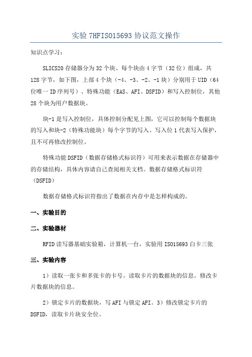
实验7HFISO15693协议范文操作知识点学习:SLICS20存储器分为32个块、每个块由4字节(32位)组成,共128字节,如下图,上部4个块(-4、-3、-2、-1块)分别用于UID(64位唯一ID序列号)、特殊功能(EAS、AFI、DSFID)和写入控制位,其他28个块为用户数据块。
块-1是写入控制位,具体控制分配见上图,它可以控制每个数据块的写入和块-2(特殊功能块)每个字节的写入。
写入位1代表写入保护,且不可再修改控制位。
特殊功能DSFID(数据存储格式标识符)可用来表示数据在存储器中的存储结构,具体内容请自己查阅相关文档。
数据存储格式标识符(DSFID)数据存储格式标识符指出了数据在内存中是怎样构成的。
一、实验目的二、实验器材RFID读写器基础实验箱,计算机一台,实验用ISO15693白卡三张三、实验内容1)读取一张卡和多张卡的卡号。
读取卡片的数据块的信息。
修改卡片数据块的信息。
2)锁定卡片的数据块,写AFI与锁定AFI。
3)修改锁定卡片的DSFID,读取卡片块安全位。
四、实验步骤1、正确连接本设备,加载HF高频读写器模块,2、选择高频读写模块,点击右键,获得右键菜单,3、选择ProtocolISO15693,4、进入ISO15693实验界面,5、拿起一张实验用高频ISO15693白卡,置于高频天线感应区,6、读操作a)点击ReadUID按钮,读取卡片的卡号d)卡片的读取方式有三种:withoutuid,withuid和other(即自定义),其中选择读取方式为withuid时必须输入卡片的卡号。
选择标识位为withoutuid,输入起始块和块的数量,在这里卡片的块的数量选择01。
输入4字节的修改数据,然后点击卡片写e)重新读取卡片,看看数据是否发生了变化。
f)选择标识位为withuid,输入起始块和块的数量,输入卡片的卡号,然后点击卡片读g)选择标识位为withuid,输入起始块和块的数量,输入卡片的卡号,输入4字节的修改数据,然后点击卡片写h)重新读取卡片,看看数据是否发生了变化。
15693协议详解

竭诚为您提供优质文档/双击可除15693协议详解篇一:15693协议小结15693协议小结本文档针对15693(即18000-3-1)协议。
在hmin到hmax的连续场中Vicc可工作;最小工作场强的值为0.15a/m;最大工作场强为5a/m。
(18000-3-1中未提到)工作频率13.56mhz±7khz。
调制采用ask方式,有两种调制度10%和100%。
由Reader 来决定调制度,tag要能够解调两种调制度。
100%的幅度调制的载波10%的幅度调制的载波,tag能工作在10%-30%之间。
数据编码采用脉冲位置调制方式(pulsepositionmodulation),tag要支持两种编码格式,Reader来选择采用那种编码格式,并会在发送soF的时候告诉tag。
两种编码格式:1)256中出1一个单字节的值由槽(pause)的位置表示。
槽的位置在连续的256个时间周期中的某一处,其中的时间周期为18.88us(256/fc),这决定了字节的值。
数据率是1.65kbps(fc/8192)。
一个时间周期的细节2)4中出1脉冲位置一次决定了2位。
连续4个形成了一个字节。
数据率是26.84kbps(fc/512)。
两种编码格式数据在传输时以soF(preamble)开头,以eoF结尾。
256中出1和4中出1有各自的soF,但两者的eoF相同。
256中出1的soF4中出1的soFeoF传输时lsb先传输。
可以使用1种或2种副载波,选择哪一种是由Reader决定的,并依据15693-3中的协议头的第一位而定。
tag要能支持这两种模式。
使用一种副载波时,负载调制副载波的频率fs1是fc/32(423.75khz)使用两种副载波时,频率fs1是fc/32(423.75khz),频率fs2是fc/28(484.28khz)当两种副载波并存时,他们之间的相位应当连续。
工作频率13.56mhz±7khz。
ISO15693非接触式IC卡射频前端电路的设计
http://www.cicmag.com(总第107期)ChinalntegratedCircult1前言ISO15693标准协议是国际上规定的用于非接触式IC卡的一种高频通信协议。
该标准协议的非接触式IC卡的读写距离长达100cm,比同是高频通信协议的ISO14443规定的10cm读写距离更大,应用范围也会更加广泛。
ISO15693标准协议规定:读卡器到卡所发送的信号为采用脉冲位置编码的10%ASK和100%ASK两种调制模式的频率都为13.56MHz的载波。
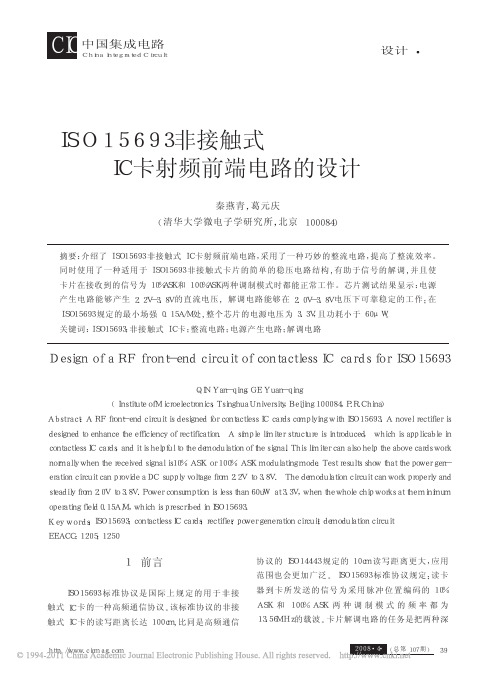
卡片解调电路的任务是把两种深秦燕青,葛元庆(清华大学微电子学研究所,北京100084)ISO15693非接触式IC卡射频前端电路的设计摘要:介绍了ISO15693非接触式IC卡射频前端电路,采用了一种巧妙的整流电路,提高了整流效率。
同时使用了一种适用于ISO15693非接触式卡片的简单的稳压电路结构,有助于信号的解调,并且使卡片在接收到的信号为10%ASK和100%ASK两种调制模式时都能正常工作。
芯片测试结果显示:电源产生电路能够产生2.2V-3.8V的直流电压,解调电路能够在2.0V-3.8V电压下可靠稳定的工作;在ISO15693规定的最小场强0.15A/M处,整个芯片的电源电压为3.3V,且功耗小于60μW。
关键词:ISO15693;非接触式IC卡;整流电路;电源产生电路;解调电路DesignofaRFfront-endcircuitofcontactlessICcardsforISO15693QINYan-qing,GEYuan-qing(InstituteofMicroelectronics,TsinghuaUniversity,Beijing100084,P.R.China)Abstract:ARFfront-endcircuitisdesignedforcontactlessICcardscomplyingwithISO15693.Anovelrectifierisdesignedtoenhancetheefficiencyofrectification.Asimplelimiterstructureisintroduced,whichisapplicableincontactlessICcards,anditishelpfultothedemodulationofthesignal.Thislimitercanalsohelptheabovecardsworknormallywhenthereceivedsignalis10%ASKor100%ASKmodulatingmode.Testresultsshowthatthepowergen-erationcircuitcanprovideaDCsupplyvoltagefrom2.2Vto3.8V.Thedemodulationcircuitcanworkproperlyandsteadilyfrom2.0Vto3.8V.Powerconsumptionislessthan60uWat3.3V,whenthewholechipworksattheminimumoperatingfield0.15A/M,whichisprescribedinISO15693.Keywords:ISO15693;contactlessICcards;rectifier;powergenerationcircuit;demodulationcircuitEEACC:1205;125039(总第107期)http://www.cicmag.com度的ASK调制信号从天线上解出,并且把它量化成数字信号送给后续的数字逻辑电路使用。
ISO15693-2

Reference number of document:ISO/I EC FCD 15693-2Date of last revision:1999-03-09ISO/IEC FCD 15693-2Identification cards -Contactless integrated circuit(s) cards -Vicinity cards -Part 2: Radio frequency power and signal interfaceContents................................................................................Page1Scope (1)2Normative references (1)3Terms and definitions (1)4Abbreviations and symbols (2)4.1Abbreviations (2)4.2Symbols (2)5Initial dialogue for vicinity cards (2)6Power transfer (3)6.1Frequency (3)6.2Operating field (3)7Communications signal interface VCD to VICC (3)7.1Modulation (3)7.2Data rate and data coding (5)7.2.1Data coding mode: 1 out of 256 (5)7.2.2Data coding mode: 1 out of 4 (6)7.3VCD to VICC frames (7)7.3.1SOF to select 1 out of 256 code (7)7.3.2SOF to select 1 out of 4 code (7)7.3.3EOF for either data coding mode (7)8Communications signal interface VICC to VCD (8)8.1Load modulation (8)8.2Subcarrier (8)8.3Data rates (8)8.4Bit representation and coding (8)8.4.1Bit coding when using one subcarrier (8)8.4.2Bit coding when using two subcarriers (9)8.5VICC to VCD frames (10)8.5.1SOF when using one subcarrier (10)8.5.2SOF when using two subcarriers (10)8.5.3EOF when using one subcarrier (11)8.5.4EOF when using two subcarriers (11)ANNEX A (Informative) Compatibility with other Card Standards (12)ForewordISO (the International Organization for Standardization) and IEC (the International Electrotechnical Commission) form the specialized system for worldwide standardization. National bodies that are members of ISO or IEC participate in the development of International Standards through technical committees established by the respective organizations to deal with particular fields of technical activity. ISO and IEC technical committees collaborate in fields of mutual interest. Other international organizations, governmental and non-governmental, in liaison with ISO and IEC, also take part in the work.International Standards are drafted in accordance with the rules given in the ISO/IEC directives part 3.In the field of information technology, ISO and IEC have established a joint technical committee, ISO/IEC JTC1. Draft International Standards adopted by the joint technical committee are circulated to national bodies for voting. Publication as an International Standard requires approval by at least 75% of the national bodies casting a vote.International Standard ISO/IEC 15693-2 was prepared by Joint Technical Committee ISO/IEC JTC1, Information technology.ISO/IEC 15693 consists of the following parts, under the general titleIdentification cards - Contactless integrated circuit(s) cards - Vicinity cards:- Part 1: Physical characteristics- Part 2: Radio frequency power and signal interface- Part 3: Anticollision and Transmission protocolsIntroductionISO/IEC 15693 is one of a series of International Standards describing the parameters for identification cards as defined in ISO/IEC 7810 and the use of such cards for international interchange.This part of ISO/IEC 15693 describes the electrical characteristics of the contactless interface between a vicinity card and a vicinity coupling device. The interface includes power and bi-directional communications.This International Standard does not preclude the incorporation of other standard technologies on the card.Contactless card standards cover a variety of types as embodied in ISO/IEC 10536 (Close coupled cards), ISO/IEC 14443 (Proximity cards), ISO/IEC 15693 (Vicinity cards). These are intended for operation when very near, nearby and at a longer distance from associated coupling devices respectively.Identification cards -Contactless integrated circuit(s) cards -Vicinity cardsPart 2:Radio frequency power and signal interface1 ScopeThis part of ISO/IEC 15693 specifies the nature and characteristics of the fields to be provided for power and bi-directional communications between vicinity coupling devices (VCDs) and vicinity cards (VICCs).This part of ISO/IEC 15693 shall be used in conjunction with other parts of ISO/IEC 15693.This part of ISO/IEC 15693 does not specify the means of generating coupling fields, nor the means of compliance with electromagnetic radiation and human exposure regulations which can vary according to country.2 Normative referencesThe following standards contain provisions which, through reference in this text, constitute provisions of this part of ISO/IEC 15693. At the time of publication, the editions indicated were valid. All standards are subject to revision, and parties to agreements based on this part of ISO/IEC 15693 are encouraged to investigate the possibility of applying the most recent editions of the standards listed below. Members of ISO and IEC maintain registers of currently valid International Standards.ISO/IEC 15693Identification cards - Contactless integrated circuit(s) cards –Vicinity cardsISO/IEC 10373Identification cards - Test methods3 Terms and definitionsFor the purposes of this International Standard, the definitions given in the first part of ISO/IEC 15693 and the following definitions apply:3.1modulation indexDefined as [a-b]/[a+b] where a and b are the peak and minimum signal amplitude respectively.3.2subcarrierRF signal produced by modulation of a carrier frequency f c with a frequency f s.4 Abbreviations and symbolsFor the purpose of this International Standard the following abbreviations and symbols apply.4.1 AbbreviationsASK Amplitude shift keyingEOF End of framePPM Pulse positioning modulationRF Radio frequencySOF Start of frameVCD Vicinity coupling deviceVICC Vicinity integrated circuit card4.2 Symbolsa Carrier amplitude without modulationb Carrier amplitude when modulatedf c Frequency of operating field (carrier frequency)f s Frequency of subcarrier modulation5 Initial dialogue for vicinity cardsThe dialogue between the VCD and the VICC (one or more VICCs may be present at the same time) is conducted through the following consecutive operations:- activation of the VICC by the RF operating field of the VCD,- VICC waits silently for a command from the VCD,- transmission of a command by the VCD,- transmission of a response by the VICC.These operations use the RF power transfer and communication signal interface specified in the following paragraphs and shall be performed according to the protocols defined in part 3 of ISO/IEC 15693.6 Power transferPower transfer to the VICC is accomplished by radio frequency via coupling antennas in the VCD and in the VICC. The RF operating field that supplies power to the VICC from the VCD is modulated for communication from the VCD to the VICC, as described in clause 7.6.1 FrequencyThe frequency (f c) of the RF operating field is 13,56 MHz ±7 kHz.6.2 Operating fieldA VICC shall operate as intended continuously between H min and H max.The minimum operating field is H min and has a value of 150 mA/m rms.The maximum operating field is H max and has a value of 5 A/m rms.A VCD shall generate a field of at least H min and not exceeding H max at manufacturer specified positions (operating volume).In addition, the VCD shall be capable of powering any single reference VICC (defined in the test methods) at manufacturer’s specified positions (within the operating volume).The VCD shall not generate a field higher than the value specified in part 1 of ISO/IEC 15693 (alternating magnetic field) in any possible VICC position.Test methods for determining the VCD operating field are defined in International Standard ISO/IEC 10373.7 Communications signal interface VCD to VICCFor some parameters several modes have been defined in order to meet different international radio regulations and different application requirements.From the modes specified any data coding can be combined with any modulation.7.1 ModulationCommunications between the VCD and the VICC takes place using the modulation principle of ASK. Two modulation indexes are used, 10% and 100%. The VICC shall decode both. The VCD determines which index is used.Depending of the choice made by the VCD, a "pause" will be created as described in Figures 1 and 2.Figure 1: 100% Modulation Waveform The clock recovery must be operational after t 4 maxFigure 2: 10% Modulation WaveformThe VICC shall be operational for any degree of modulation index from between 10% and 30%.Min (µs)t 16,0t 22,1t 30Max (µs)9,44t 14,5a105%100%95%5%tt 2t 1t 360%t 4t 400,8hf, hr 0,1 (a-b) maxy 0,05 (a-b)t1t2hfyhrb t3a tMin 6,0 µs t23,0 µs t30Max9,44 µst14,5 µs ModulationIndex t10.10.3y7.2 Data rate and data codingData coding shall be implemented using pulse position modulation.Two data coding modes shall be supported by the VICC. The selection shall be made by the VCD and indicated to the VICC within the Start of frame (SOF). See 7.3.7.2.1 Data coding mode: 1 out of 256The value of one single byte shall be represented by the position of one pause. The position of the pause on 1 of 256 successive time periods of 18,88 µs (256/f c ),determines the value of the byte. In this case the transmission of one byte takes 4,833 ms and the resulting data rate is 1,65 kbits/s (f c /8192).Figure 3 illustrates this pulse position modulation technique.Figure 3: 1 out of 256 coding modeIn Figure 3 Data E1 hex (225 dec) is sent by the VCD to the VICC.The pause shall occur during the second half of the position of the time period that determines the value, as shown in Figure 4.Figure 4: Detail of one time period PulseModulatedCarrier | | | | | | | | | | | | | | | | | | | | | | | | | | | | | | | | | | |0 1 2 3 4 . . . . . . . . 2 . . . . . . . . . . . . . . . . . . . . . 2 2 2 22 5 5 5 5 5 234 54,833 ms9,44 µs 18,88 µsPulseModulatedCarrier9,44 µs18,88 µs. . . . . | | | | . . . . .2 2 22 2 24 5 6Time periodone of 2567.2.2 Data coding mode: 1 out of 4Pulse position modulation for 1 out of 4 mode shall be used, in this case the position determines two bits at a time. Four successive pairs of bits form a byte, where the least significant pair of bits is transmitted first.The resulting data rate is 26,48 kbits/s (f c /512).Figure 5 illustrates the 1 out of 4 pulse position technique and coding.Figure 5: 1 out of 4 coding modeFor example Figure 6 shows the transmission of E1 hex (225 dec) by the VCD.Figure 6: 1 out of 4 coding example 75,52 µs9,44 µs 9,44 µsPulse position for "00"75,52 µs9,44 µs28,32 µs Pulse position for "01" (1 = LSB)75,52 µs 9,44 µs47,20 µsPulse position for "10" (0 = LSB)75,52 µs 9,44 µs66,08 µsPulse position for "11"75,52 µs 0075,52 µs 0175,52 µs 1175,52 µs107.3 VCD to VICC framesFraming has been chosen for ease of synchronization and independence of protocol.Frames shall be delimited by a start of frame (SOF) and an end of frame (EOF) and are implemented using code violation. Unused options are reserved for future use by ISO/IEC.The VICC shall be ready to receive a frame from the VCD within 300 µs after having sent a frame to the VCD.The VICC shall be ready to receive a frame within 1ms of activation by the powering field.7.3.1 SOF to select 1 out of 256 codeThe SOF sequence described in Figure 7 selects the 1 out of 256 data coding mode.Figure 7: Start of frame of the 1 out of 256 mode7.3.2 SOF to select 1 out of 4 codeThe SOF sequence described in Figure 8 selects the 1 out of 4 data coding mode.Figure 8: Start of frame of the 1 out of 4 mode7.3.3 EOF for either data coding modeThe EOF sequence for either coding mode is described in Figure 9.9,44 µs9,44 µs37,76 µs 37,76 µs 9,44 µs 9,44 µs37,76 µs 37,76 µs9,44 µs 37,76 µs 9,44 µs9,44 µsFigure 9: End of frame for either mode8 Communications signal interface VICC to VCDFor some parameters several modes have been defined in order to allow for use in different noise environments and application requirements.8.1 Load modulationThe VICC shall be capable of communication to the VCD via an inductive coupling area whereby the carrier is loaded to generate a subcarrier with frequency f s. The subcarrier shall be generated by switching a load in the VICC.The load modulation amplitude shall be at least 10 mV when measured as described in the test methods.Test methods for VICC load modulation are defined in International Standard ISO/IEC 10373.8.2 SubcarrierOne or two subcarriers may be used as selected by the VCD using the first bit in the protocol header as defined in 15693-3. The VICC shall support both modes.When one subcarrier is used, the frequency f s1 of the subcarrier load modulation shall be f c/32 (423,75 kHz).When two subcarriers are used, the frequency f s1 shall be f c/32 (423,75 kHz), and the frequency f s2 shall be f c/28 (484,28 kHz).If two subcarriers are present there shall be a continuous phase relationship between them.8.3 Data RatesA low or high data rate may be used. The selection of the data rate shall be made by the VCD using the second bit in the protocol header as defined in 15693-3. The VICC shall support those data rates show in Table 1.Data Rate Single Subcarrier Dual SubcarrierLow6,62 kbits/s (f c/2048)6,67 kbits/s (f c/2032)High26,48 kbits/s (f c/512)26,69 kbits/s (f c/508)Table 1: Data rates8.4 Bit representation and codingData shall be encoded using Manchester coding, according to the following schemes.All timings shown refer to the high data rate from the VICC to the VCD. For the low data rate the same subcarrier frequency or frequencies are used, in this case the number of pulses shall be multiplied by 4 and all times will increase by this factor.8.4.1 Bit coding when using one subcarrierA logic 0 starts with 8 pulses of 423,75 kHz (f c/32) followed by an unmodulated time of 18,88 µs (256/f c). As shown in Figure 10.18,88 µs37,76 µsFigure 10: Logic 0A logic 1 starts with an unmodulated time of 18,88 µs (256/f c) followed by 8 pulses of 423,75 kHz (f c/32). As shown in Figure 11.18,88 µs37,76 µsFigure 11: Logic 18.4.2 Bit coding when using two subcarriersA logic 0 starts with 8 pulses of 423,75 kHz (f c/32) followed by 9 pulses of 484,28 kHz (f c/28). As shown in Figure 12.18,88 µs37,46 µsFigure 12: Logic 0A logic 1 starts with 9 pulses of 484,28 kHz (f c/28) followed by 8 pulses of 423,75 kHz (f c/32). As shown in Figure 13.Figure 13: Logic 18.5 VICC to VCD framesFraming has been chosen for ease of synchronization and independence of protocol.Frames are delimited by a Start of frame (SOF) and an End of frame (EOF) and are implemented using code violation. Unused options are reserved for future use by the ISO/IEC.All timings shown below refer to the high data rate from the VICC to the VCD.For the low data rate the same subcarrier frequency or frequencies are used, in this case the number of pulses shall be multiplied by 4 and all times will increase by this factor.The VCD shall be ready to receive a frame from the VICC within 300 µs after having sent a frame to the VICC.8.5.1 SOF when using one subcarrierSOF comprises 3 parts:• an unmodulated time of 56,64 µs (768/f c ),• 24 pulses of 423,75 kHz (f c /32),• a logic 1 which starts with an unmodulated time of 18,88 µs. (256/f c ) followed by 8pulses of 423,75 kHz (f c /32).The SOF for one subcarrier is illustrated in Figure 14.Figure 14: Start of frame when using one subcarrier8.5.2 SOF when using two subcarriersSOF comprises 3 parts:• 27 pulses of 484,28 kHz (f c /28),• 24 pulses of 423,75 kHz (f c /32),• a logic 1 which starts with 9 pulses of 484,28 kHz (f c /28) followed by 8 pulses of423,75 kHz (f c /32).37,46 µs18,58 µs 56,64 µs 37,76 µs56,64 µsThe SOF for 2 subcarriers is illustrated in Figure 15.Figure 15: Start of frame when using two subcarriers8.5.3 EOF when using one subcarrierEOF comprises 3 parts:• a logic 0 which starts with 8 pulses of 423,75kHz (f c /32), followed by an unmodulated time of 18,88 µs (256/f c ),• 24 pulses of 423,75 kHz (f c /32),• an unmodulated time of 56,64 µs (768/f c ).The EOF for 1 subcarrier is illustrated in Figure 16.Figure 16: End of frame when using one subcarrier8.5.4 EOF when using two subcarriersEOF comprises 3 parts:• a logic 0 which starts with 8 pulses of 423,75 kHz (f c /32) followed by 9 pulses of484,28 kHz (f c /28),• 24 pulses of 423,75 kHz (f c /32),• 27 pulses of 484,28 kHz (f c /28).The EOF for 2 subcarriers is illustrated in Figure 17.Figure 17: End of frame when using 2 subcarriers 55,75 µs 37,46 µs56,64 µs 37,76 µs 56,64 µs56,64 µs 37,46 µs 55,75 µs56,64 µsANNEX A (Informative)Compatibility with other Card StandardsThis standard does not preclude the addition of other existing card standards on the VICC, such as those listed as follows.ISO/IEC 7811Identification cards - Recording techniqueISO/IEC 7812Identification cards - Identification of issuersISO/IEC 7813Identification cards - Financial transaction cardsISO/IEC 7816Identification cards - Integrated circuit(s) cards with contacts ISO/IEC 10536Identification cards - Contactless integrated circuit(s) cards -Close-coupled cardsISO/IEC 14443Identification cards - Contactless integrated circuit(s) cards -Proximity cards。
- 1、下载文档前请自行甄别文档内容的完整性,平台不提供额外的编辑、内容补充、找答案等附加服务。
- 2、"仅部分预览"的文档,不可在线预览部分如存在完整性等问题,可反馈申请退款(可完整预览的文档不适用该条件!)。
- 3、如文档侵犯您的权益,请联系客服反馈,我们会尽快为您处理(人工客服工作时间:9:00-18:30)。
竭诚为您提供优质文档/双击可除iso15693协议中文版
篇一:iso15693与iso14443区别
iso14443
is014443a/b:超短距离智慧卡标准。
这标准订出读取距离7-15厘米的短距离非接触智慧卡的功能及运作标准,使用的频率为13.56mhz。
is014443定义了typea,typeb两种类型协议,通信速率为106kbit/s,它们的不同主要在于载波的调制深度及位的编码方式。
typea采用开关键控(on-offkeying)的manchester编码,typeb采用nRz-l的bpsk编码。
typeb 与typea相比,具有传输能量不中断、速率更高、抗干扰能力强的优点。
RFid的核心是防冲突技术,这也是和接触式ic卡的主要区别。
is014443-3规定了typea和typeb的防冲突机制.二者防冲突机制的原理不同,前者是基于位冲突检测协议,而typeb通信系列命令序列完成防冲突.目前的第二代电子身份证采用的标准是is014443typeb协议。
iso15693
is015693(isosc17lwg8):短距离智慧卡标准,这标准订出读取距离可高达一米非接触智慧卡,使用的频率为
13.56mhz,设计简单让生产读取器的成本比is014443低,大都用来做进出控制、出勤考核等,现在很多企业使用的门禁卡大都使用这一类的标准。
is015693采用轮寻机制、分时查询的方式完成防冲突机制。
防冲突机制使得同时处于读写区内的多个标签的正确操作成为可能,既方便了操作,也提高了操作的速度。
iso10536,iso15693,iso14443的区别
iso10536标准主要发展于1992到1995年间,由于这种卡的成本高,与接触式ic卡相比优点很少,因此这种卡从未在市场上销售。
iso14443和iso15693标准在1995年开始操作,单个系统于1999年进入市场,两项标准的完成则是在2000年之后。
二者皆以13.56mhz交变信号为载波频率:iso15693读写距离较远,当然这也与应用系统的天线形状和发射功率有关;而iso14443读写距离稍近,但应用较广泛,目前的第二代电子身份证采用的标准是iso14443typeb协议。
iso14443定义了typea、typeb两种类型协议。
通信速率为106kbits/s,它们的不同主要在于载波的调制深度及位的编码方式。
从pcd向picc传送信号时,typea采用改进的miller
编码方式,调制深度为100%的ask信号;typeb则采用nRz 编码方式,调制深度为10%的ask信号。
篇二:实验7hFiso15693协议操作
知识点学习:
iso/iec15693协议标准的高频RFid无源ic卡,专为供应链与运筹管理应用所设计,具有高度防冲突与长距离运作等优点,适合于高速、长距离应用。
包括icodesli-s、sl2-s 等多系列产品,目前icode是高频(hF)RFid标签方案的业界标准。
icodesli-s系列sl2ics20芯片的内部构成如上图,可分为射频处理单元、数据控制单元和eepRom存储单元。
在数据控制单元里对数据进行反碰撞、认证
和存储控制等处理。
slics20存储器分为32个块、每个块由4字节(32位)组成,共128字节,如下图,上部4个块(-4、-3、-2、-1块)分别用于uid(64位唯一id序列号)、特殊功能(eas、aFi、dsFid)和写入控制位,其他28个块为用户数据块。
uid占用块-4和块-3共8个字节(64位),是厂商写入的世界唯一标签识别序列号,用户不可更改,在uid中包含厂商代码、产品分类代码和标签芯片生产序列代码,uid的代码构成如上图。
块-1是写入控制位,具体控制分配见上图,它可以控制每个数据块的写入和块-2(特殊功能块)每个字节的写入。
写入位1代表写入保护,且不可再修改控制位。
特殊功能eas(electronicarticlesurveillance,电子防盗系统)主要用来防止物品被盗,标签管理者可以设置(eas=1)和清除(eas=0)eas标识,当设置有eas标识的标签通过读写器的作用范围时,读写器会识别eas标识,发出警报。
eas的数据结构如下图,eas的lsb的第一位(e位)写1代表eas标示有效,写0代表清除eas标示,其他位无效。
特殊功能aFi(applicationFamilyidenfifier,应用族标识符),可事先规定应用族代码并写入aFi字节,在处理多个标签的时候进行分类处理。
例如在物流中心处理大量货物时,可根据标签上的aFi应用族标识符来区分是出口货物还是内销货物。
aFi被编码在一个字节里,由两个半字节组成。
aFi的高位半字节用于编码一个特定的或所有应用族,aFi的低位半字节用于编码一个特定的或所有应用子族。
子族不同于0的编码有其自己的所有权。
下图是aFi的族编码定义。
标签支持的aFi是可选的。
假如标签不支持aFi,并且假如aFi标志已设置,标签将不应答任何请求中的aFi值。
假如标签支持aFi,标签将根据表1中匹配的规则作出应答。
特殊功能dsFid(数据存储格式标识符)可用来表示数。