多用户电表的使用方法
三相电子式多功能电能表使用说明书

DTSD1277型DSSD1277-B型三相电子式多功能电能表使用说明书安装、使用产品前请阅读使用说明书石家庄科林自动化有限公司目录1概述 ....................................................................................................................................错误!未定义书签。
2工作原理 ............................................................................................................................错误!未定义书签。
3技术参数 ............................................................................................................................错误!未定义书签。
3.1主要型号 ...............................................................................................................................错误!未定义书签。
3.2主要技术参数 .......................................................................................................................错误!未定义书签。
3.3抄表及全失压电池 ...............................................................................................................错误!未定义书签。
山东晨辉 预付费多用户电表说明书

(预付费型)
使
用
说
明
书
鲁制 00000399号
山东晨晖电子科技有限公司
一、简介…………………………………………………2
二、技术特点……………………………………………2
三、技术参数……………………………………………4
四、型号说明……………………………………………4
五、外型及尺寸…………………………………………5
当出现拉闸报警断电后,用户应尽快到售电中心购买电量输入电能表,否则,用户用完拉闸报警断电值后,电能表将进行余额为零断电。
2、余额为零断电
余额为零断电是电能表显示用户购电量为0度时,该户的继电器自动断电,提醒用户必须买电,这时该户的户号闪烁,用电量显示为—0000.0。此时用户应尽快到售电中心购买电量输入电能表。
要求显示用户门牌号的单位,订货时必须注明每台电能表的用户门牌号编排方法和次序。
2、IC卡提取方式
DDSH1540型预付费多用户电能表通过RS485接口和YF-1型智能卡读写器联接,每台YF-1型智能卡读写器可管理1-16台DDSH1540型预付费多用户电能表,用户可在YF-1型智能卡读写器中插入该户的用户卡或检测功能卡,在YF-1型智能卡读写器显示屏上可显示出剩余电量。
当出现拉闸报警断电时,可采取三种方法使电能表正常供电:
(1)在电能表显示到该户时按一下电表下边的上电按钮,这时该户即可正常用电,该户的户号也不再闪烁。
(2)通过IC卡售电的用户可把该户的IC卡插入YF-1型智能卡读写器,这时该户即可正常用电,该户的户号也不再闪烁。
(3)通过计算机联网售电的用户可通过计算机软件系统对该用户进行上电,这时该户即可正常用电,该户的户号也不再闪烁。
宝工 MT-1820N联机型多功能数字电表 使用说明书

MT-1820N3 5/6 True-RMS Auto Range MultimeterUser’s Manual1st Edition, 2024©2024 Copyright by Prokit’s Industries Co., Ltd.I. INTRODUCTIONThe instrument is a stable and highly reliable 3 5/6-digit multi-meter, it uses the LCD with 33mm high figure to make the reading clear, the display intuitive and the operation convenient. The instrument can measure DC and AC voltage, DC and AC current, Resistance, Capacitance, Temperature, Frequency, Duty Circle, Electromagnetic induction, Live wire judgment, Transistor, Diode and Continuity test. At the same time, it is also designed with 61 segments of analog bar display, unit symbol display, data hold, relative value measurement, USB computer interface, auto/manual range conversion, auto power off and alarm functions. The instrument adopts a 4-bit microprocessor that can directly drive LCD and a dual integral A/D conversion integrated circuit, which provide a high solution and high accuracy digital displaying driver. The instrument has complete functions, high measurement accuracy, and is easy to use. It is an ideal tool for laboratories, factories, radio enthusiasts, and households.II.OPEN THE PACKAGE FOR CHECKINGOpen the box, take out the meter, checking the items below whether they are missing or damaging:K type probe (-20℃~250℃) 1pcMulti-function socket 1pcTest leads 1pairUSB Cable(TYPE-C) 1pcCD software 1pcUser manual 1pcPlease contact with your supplier if you find out any problems.III. Safety Operation GuidelinesThis series meter meets the standard of IEC61010 (the safety standardsrequest issued by IEC or equal GB4793.1 standards). Read it beforeoperation.1.Input over range is prohibited in each range during the test.2.Measure voltage above 24V, current above 10mA, and AC power lines withinductive loads; Be cautious of electric shock when measuring AC powerlines during power fluctuations.testing point.4.Select correct function and range, beware of wrong operation. Please stillbe careful although the meter got a function of full range protection.5.Do not operate the meter if the battery and back cover is not fixed.6.Measure resistance, capacitance, temperature, diode, on/off test, do notinput voltage signals.7.Remove test leads from test point and turn off the power before replacingbattery and fuse.8.Please comply with local and national safety regulations. Wear personalprotective equipment (such as approved rubber gloves, face masks, and flame-retardant clothing etc.) to prevent the injury from electric shock and arc when charged conductors are exposed.9.Make measurements using only the correct measurement standard class(CAT), voltage and current rated probe, test conductor and adapter. 10.Safety symbols:“” exists high voltage“” GND“” Dual Insulation “” Must Refer to Manual“ ” ” Low BatteryV.SPECIFICATIONS1)Display mode: LCD display.2)Max. indication: 5999(3 5/6 bits), auto polarity indication3)Simulated bar 30 times/second, 61 segments of simulated bargraph display.4)Measuring method: Dual integral A/D conversion5)Sampling rate: Approx. 3times/second6)Over range indication: “OL” displays.7)Low battery: The “ ” displays.8)Operating environment: (0 ~ 40) ℃, humidity<80%RH.9)Storage environment:-10℃~50℃,humidity<80%RH.10)Power: Four 1.5V AAA batteries, LR0311)Dimension: 189mm×88mm ×56mm.12)Weight: approx. 380g (not include batteries).VI. EXTERNAL STRUCTUR1. LCD display2. Function knob3. Measuring input terminal4..Measurement of maximum/minimum values5. Function /Duty Cycle6. Data hold/ backlight7.Automatic/manual range8. Select button9. USB communication/relative value measurement10. Screws for fixing the battery box.11. Bracket12. Test leads fixed frame13. USB port (dust cover)VII.LCD DISPLAY①USB communication connection②AC true RMS measurement③DC measurement④Maximum measurement⑤Minimum measurement⑥Data hold⑦Relative value measurementVIII.KEY Function1. HOLD: Keep the reading, press this button to display that the value is locked, and then press this button again to unlock the status. Press and hold for more than 3 seconds to turn on or off the backlight. The backlight will automatically turn off for 2 minutes after being turned on.Warning: to prevent possible electric shock, fire, or personal injury, do not use the data hold function to measure the unknown voltage. When open the HOLD function, the LCD will keep original data when measuring a different voltage.2. Hz/DUTY:Frequency/Duty Circle selection button, press the button in the frequency gear can switch frequency and duty cycle testing; Press the button in the AC voltage or AC current gear can switch between AC voltage or current/ frequency/duty cycle tests.3. SELECT: Function selection, Short press this button to switch between AC and DC voltage tests in the voltage range; Cyclic switching of resistance, diode, and on/off tests can be performed in resistance, diode, and on/off modes; Switch between Fahrenheit and Celsius testing in the temperature range; Switching between AC and DC current testing in current mode; You can switch betweenelectromagnetic induction and live wire detection tests in the electromagneticinduction and live wire detection modes.4. MAX/MIN: Maximum and minimum value testing. Short press this function to enter MAX mode, which maintains the maximum measured value. Press this button again to enter MIN mode, which maintains the minimum value. After entering MAX/MIN mode, the display will maintain the maximum or minimum value. Long press the MAX/MIN button for 2 seconds to exit MAX or MIN measurement. In the maximum/minimum measurement mode, the instrument will be locked to the current range. If the instrument displays OL, it indicates that themeasured value has exceeded the current range.5. RANGE:Automatic/manual range switching. When turned on, it defaults to automatic range. Press this button to switch to manual range, and the screen displays the "RANGE" character. In manual range mode, each press of the gear range will jump up one gear, and when it reaches the highest gear, press this button again to jump back to the lowest gear, and cycle in sequence. If this key is pressed for more than 2 seconds, it will switch back to the automatic range andthe "RANGE" character will disappear from the screen.6. USB/REL: Short press this button to measure relative values, press again to cancel relative value measurement. In relative value measurement mode, the instrument will be locked to the current range (except for the capacitance range). If the instrument displays OL, it indicates that the measured value has exceeded the current range. Long press this button for more than 2 seconds to activate the USB communication function. There is a communication symbol displayed on the LCD screen, indicating that USB data output is turned on. The instrument enters a data transmission state and can transmit data to the outside. Use the USB computer interface cable attached to the instrument to connect it to the computer, which can record, analyze, process, and print the measured data; If you press this button again for more than 2 seconds, the communication symbol will disappear from the LCD screen. At this time, the USB data output will be turned off, and the data transmission status will stop. The instrument does not have an automatic shutdown function in communication mode.IX.MEASUREMENT OPERATION INSTRUCTIONSFirst please pay attention to check the battery, put the knob in the desired measurement position, if it is with low battery, the LCD display will appear " " symbol. Note the symbol " " next to the test lead jack which warns you to pay attention to the test voltage and current, do not exceed the indicated value.1.DCV and ACV measurement1-1.Turn the knob to the AC/DC voltage range, and the instrument will start in automatic range DC voltage mode, displaying the "AUTO"symbol. Press the "RANGE" button to switch to manual range mode. To measure AC voltage, press the "SELECT" button to select the AC voltage. When measuring AC voltage, you can briefly press the Hz/DUTY button to switch to the accompanying frequency or duty cycle test.1-2.Insert the red and black probes into the "VΩHz" and "COM" holes respectively.1-3.Connect the test lead in parallel to the test point on the circuit under test and display the polarity of the red probe line and the voltage value under test on the screen simultaneously.Attention:(1)Do not measure DC voltage higher than 1000V or AC voltagehigher than 750V.(2)Wear safety protective equipment when measuring voltages above24V and be careful to avoid electric shock. Immediately disconnect the probe from the measured circuit after testing.(3)The manual range mode, such as LCD displaying "OL", indicatesthat the range has been exceeded. Please select a higher range gear to complete this measurement.2.DC and AC current measurement2-1.Insert the red probe into the "uA mA" or "10A" hole, and the black probe into the "COM" hole. Enter the maximum values of 600mAand 10A respectively.2-2.Turn the knob to the current position, and the starting state of the instrument is DC current mode. Press the "SELECT" button to select the AC current measurement method. When measuring AC current, short press the Hz/DUTY key to perform accompanying frequency or duty cycle testing. Then connect the instrument in series into the measured circuit, and the measured current value and the polarity of the red probe will be displayed on the screen simultaneously.2-3.If "OL" is displayed on the display screen, it indicates that the measured current has exceeded the current range. Please select a higher range for measurement.Attention:(1)In the 10A range, currents greater than 10A cannot be measured. Inthe "uA" range, currents greater than 6000uA cannot be measured.In the "mA" range, currents greater than 600mA cannot be measured. Otherwise, the fuse may be blown, or the instrument may be damaged.(2)When the probe is inserted into the current input terminal, it isstrictly prohibited to connect the probe in parallel with any circuit, otherwise it may damage the instrument and endanger user safety.After completing all measurements, immediately disconnect the probe from the measured circuit.3.Resistance measurement3-1. Turn the knob to the "" position, and the default on/off test will be performed upon startup. Short press the "SELECT" button to cycle through on/off, diode, and resistance tests. Insert the red and black probes into the "VΩHz" and "COM" holes respectively.3-2. Connect the test end of the probe in parallel to the measured resistance, and the measured resistance will be displayed on the screen.3-3. Press the "RANGE" button to select the manual range operation mode.3-4. If the display shows "OL", it indicates that the current range has been exceeded. Please select a higher range to complete.Attention:(1) When measuring resistance, all power sources in the tested circuitmust be turned off first, and all capacitors must be fully discharged.(2) When measuring resistance, the presence of any voltage can causeinaccurate readings. If the protection voltage exceeds 250V, it may damage and endanger the safety of the user.(3) When using 600Ω range, the probe should be short circuited first tomeasure the lead resistance, and then the relative value can be measured by short pressing the "USB/REL" button.4.Diode and continuity test4-1.Turn the knob to the ""position, and the instrument will perform a default on/off test when turned on, as shown in the figure. 4-2.Insert the red and black probes into the "VΩHz" and "COM" input terminals respectively, and then press the "SELECT" button to select the diode or on/off measurement.4-3.Diode measurement: Connect the red probe to the positive pole of the diode and the black probe to the negative pole of the diode and read the result from the display screen.4-4.On/off measurement: Connect the watch pen to both ends of the line to be tested. If the resistance value between the two ends is less than about 50Ω, the built-in buzzer will sound.Attention:(1)If the diode is open circuit or polarity is reversed, "OL" will bedisplayed on the display screen.(2)When checking the diode, all power sources in the tested circuitmust be disconnected first, and all capacitors must be fully discharged.(3)After completing the measurement, immediately disconnect theprobe from the measured circuit.5.Capacitance Measurement5-1.Turn the knob to the capacitor position and insert the red and black probe wires into the "VΩHz" and "COM" input terminals respectively.5-2.Connect the test end of the probe wire in parallel to the measured capacitance, and the measured capacitance value will be displayed on the display screen.5-3.If the display screen shows "OL", it indicates that the measured capacitance value has exceeded the current range, or the capacitance is short circuited.5-4.Read the current result from the display screen.Attention:(1)When measuring capacitance, all power sources in the tested circuitmust be disconnected first, and all capacitors must be fully discharged.(2)When measuring large capacitance, it takes a long time, about 6seconds at 100uF.(3) After completing all measurements, immediately disconnect theprobe from the measured circuit.(4)UNIT: 1mF=1000uF 1uF =1000nF 1nF=1000pF6.Frequency/Duty cycle measurement6-1.Turn the knob to the "Hz" position. Insert the red and black probe into the "VΩHz" and "COM" input terminals respectively.6-2.Connect the test end of the probe wire in parallel to the signal source to be tested and read the result from the display screen.6-3.When performing frequency measurement, short press the "Hz/DUTY" button to cycle between frequency and duty cycle tests. 6-4.When conducting AC current and voltage measurements, press the "Hz/DUTY" button to enter frequency measurement, then pressthe "Hz/DUTY" button again to enter duty cycle measurement, and press the "Hz/DUTY" button a third time to return to the original measurement state.Attention:(1)Do not input signals higher than 60V, otherwise it may damage theinstrument and endanger personal safety.(2)After completing all measurements, immediately disconnect theprobe from the measured circuit.7.Triode measurement7-1.Turn the knob to the "hFE" position.7-2.Insert the transistor accessory into the "uAmA" and "COM" holes. 7-3.Insert the "E B C" hole corresponding to the "NPN" or "PNP" of the transistor accessory according to the model of the tested transistor.7-4.Read the results from the display screen.Attention:It is strictly prohibited to input voltage signals into the "uAmA", "COM", and transistor accessory holes, otherwise it may damage the instrument and endanger user safety.8.Temperature measurement8-1.Turn the knob to the "℃℉" position.8-2.Insert the input end of the temperature probe into "COM" and "V ΩHz", and the positive end into "VΩHz". Place the sensing end of the temperature probe on the surface of the measured object, as shown in the figure.8-3.Read the current measurement result from the display screen.8-4.Press "SELECT" to select Fahrenheit, then press "SELECT" to select Celsius, and cycle through them one by one.Attention:(1)When the input terminal is open, it displays room temperature.(2)Please do not replace the vorticity sensor casually, otherwise theaccuracy of the measurement cannot be guaranteed.(3)It is strictly prohibited to input voltage in the temperature range,otherwise there is a risk of damaging the instrument!9.Non-contact voltage induction measurement (NCV)9-1.Turn the knob to “NCV/Live” position, which defaults to the NCV function and corresponds to the LCD display of EF.9-2.The NCV induction voltage range is 48V~220V. Place the upper part of the instrument close to the tested live AC power line. When the AC voltage is sensed, the red indicator light on the upper part of the instrument will flash and the buzzer will sound a "drip" alarm.The closer it is to the AC power line, the stronger the induced AC voltage, and the corresponding flashing indicator light and buzzer alarm will sound faster.10.Live line recognition10-1.Insert the red probe into the "VΩHz" socket.10-2.Turn the knob to the "NCV/Live" position, short press the SELECT key to switch to the Live function, and the LCD will display LIVE.e a red probe to contact the tested position or socket. If there is an audible and visual alarm, the tested point is a live wire. If thereis no change, the tested point is a zero wire or not powered on.11.Automatic power on/offAfter the instrument is stopped for 15 minutes, it will automatically shut down (power off) and enter a sleep (power off) state. One minute before the power off, the built-in buzzer will sound 5 prompts. After one minute, a long sound will enter a sleep (power off) state. Short press the "SELECT" button in sleep mode to wake up the instrument. Press the "SELECT" button to turn on the device, and the instrument will enter the cancel automatic shutdown mode.munication connection (USB data transfer operation)12-1.Open the USB dust cover on the front end of the instrument panel. 12-2.Connect the USB data cable to the instrument USB port and connect it to the computer USB interface.12-3.Open the upper software and set the COM port. Long press the "USB/REL" button on the instrument panel to enable communication function. At this time, the instrument panel displays communication symbols, which can be used for upper computer software transmission and data saving. If communication function is not used, long press the "USB/REL" button to turn off communication function. In communication mode, the instrument panel cancels the automatic shutdown function.X.Technical characteristicsAccuracy: ± (a% × reading + digit)Environment temperature: (23±5) ℃Relative humidity: <75%RH.One year guarantee since production date.Display: True RMS value of voltage; The accuracy is 5% to 100% of the range.V oltage range short circuit allows for a base number of ≤ 5 words; Duty cycle display: (0.1% to 99.9%).The frequency and duty cycle test amplitude of AC voltage should be ≥ 1VMaximum input current :10A (no more than 15 seconds). Accuracy is 5% to 100% of the range.Maximum input current :10A(no more than 15 seconds); Accuracy is 5% to 100% of the rangeFrequency response: Sinusoidal and triangular waves 40Hz~1kHz; Duty cycle display: (0.1% to 99.9%);AC current accompanied by frequency and duty cycle test, uA level ≥ 300uA, mA level ≥ 30mA, A level ≥ 3A60uF 0.01uF 600uF ±(5.0%+10d) 0.1uF6mF 0.001mF 60mF 0.01mF 99.9mFreferenced0.1mFMeasuring range of accuracy: 10% - 100% of the range Large capacitance response time: ≥1uF about 8sMeasurement error does not include lead distribution capacitance. 7. Frequency / Duty CycleRange AccuracyResolution Overload protection10Hz ±(0.5%+4d) 0.01Hz 250VDC/AC RMS 100Hz 0.1Hz 1kHz 0.001kHz 10kHz 0.01kHz 100kHz 0.1kHz 1MHz0.001MHz30MHz 0.01MHzInput sensitivity: ≥3Vpp. Duty cycle display: (0.1% -99.9%)Frequency input amplitude requirement: 10Hz-100kHz: 1Vrms ≤ Input amplitude ≤ 20Vrms. 100kHz -30MHz: 3Vrms ≤ Input amplitude ≤ 20Vrms. Duty cycle: within the range of 10% -90%, suitable for square waves of 10Hz-1kHz. 30% -70% range, suitable for square waves of 1KHz-30MHz. Input amplitude: 1Vrms ≤ Input amplitude ≤ 20Vrms 8. Diode and continuity Testrange show value test conditionDiode forward voltagedrop The forward DC current is about 1.6mA, and the reverse voltage is about3.0VWarning: Do not input voltage at this range. Overload protection: 250V DC/AC RMS 752Sensor: Type-K thermocouple (Ni-Cr – Ni-Si) banana probeXI. Replace the battery or fuse.Refer to Figure 12 and follow the steps below:1. Move away the test leads from the circuit under test, pull out the test leadfrom the input jack, turn the range knob to the “OFF” range to turn off the power.2. Use a screwdriver to twist off the screws on the battery cover and removethe battery cover and bracket.3. Take out the old battery or the broken fuse, then replace with a new alkalinebattery or a new fuse.4. Close the battery cover and use a screwdriver to tighten the screws on thebattery cover.5.Battery specifications:4 * 1.5V AAA alkaline batteries6.Fuse specifications:mA input fuse "FS1": φ5 x 20mm 600mA 250V10A input fuse "FS2": φ5 x 20mm 10A 250VNote: When the low voltage "" symbol displays on the LCD, the battery should be replaced immediately, otherwise the measuring accuracy will be affected.XII.Instrument MaintenanceIt is an accurate meter. Do not try to modify the electric circuit.1. Pay attention to the waterproof, dustproof and break proof of the meter.2. Please do not store or use it in environment of high temperature, high humidity, high flammability or strong magnetic.3. Please wipe the meter with a damp cloth and soft detergent, and abrasive and drastic solvent such as alcohol are forbidden.4. If do not operate for a long time, should take out the battery to avoid leakage.5. When replacing fuse, please use another same type and specification fuse.XIII.Trouble ShootingIf your meter is not working properly, the following methods can help you Quick resolution of a - general problem. If the fault still cannot be removed, please contact the repair center or dealer.Appear symbolCurrent no inputThis user’s manual is subject to any change without further notice.The content in this user’s manual is deemed correct; if you find any mistake, omission, etc., please contact the manufacturer.We will not be held liable for any accidents or harms caused due to your wrong operations.The functions set forth in this user’s manual shall not be regarded as reasons for applying this product for special purposes.3-5/6真有效值自動量程電錶使用手冊一、產品概述MT-1820N 3 5/6真有效值自動換檔電錶是一台性能穩定、可靠性高的數位萬用電錶。
YTZWP型 多用户智能电能表说明书

YTZWP型多用户智能电能表使用说明书北京卓川电子科技有限公司一、用途及使用范围YTZWP型多用户集中式电能表采用微电子处理技术和S M T 表面封装焊接及在线测试技术,能将多达3 9 户的用电量集中检测,逐户循环显示。
采用单片机处理系统实现检测,分户计量与显示,体积小、抗电磁干扰、功耗低、使用寿命长、智能抄表等优点。
主要用于新建楼房、旧楼改造、学生公寓等用电计量。
二、功能特点1、多用户集中式电能表准确计量正负两个方向的有功电能,防止窃电。
2、通过数码管清晰显示每户用电信息,每隔四秒钟显示一户。
3、具有红外抄表功能,在现场两秒钟就可将一个单元用电信息抄出、节省时间,准确无误。
4 、宽量程10(5 0)A ,适应负载变化大的用户。
5、根据用户需求可单相、三相入户,使用方便。
6 、整机功耗低(小于6VA )节能效果明显。
三、技术参数1 、计量户数:单相39户或三相13户2、工作电动:AC 150~250V3、标定电流:10(50)A4、启动电流:0.5%IB5、工作温度:-20℃~60℃6 、精度等级:2 0 . 级四、型号说明例如型号为YTZWP -6S+8D表示是8 户单相6 户三相集中式电能表五、外形尺寸(单位: mm)七、接线图八、抄表方法1、直读抄表本电能表显示窗口有两排L E D 数码管,上排显示用户号:如0 0 01 表示第一户;0002表示第二户...上排的用户号0001对应下排第一户的用电量,依此类推,最高显示999999Kw.h,每四秒钟切换一户。
2、红外抄表器抄表用本公司生产的红外抄表器在现场距离被抄多用户表小于4 米范围内,对准电表按通讯键2 秒左右,如红外抄表器显示通讯成功,抄表完毕,最多可抄288只多用户表,并将数据传入计算机。
详见红外抄表器使用手册。
3、计算机机联网远程自动抄表。
用户选用。
九、检验与校表YTZWP电能表前面有一个五芯插孔,称为检定口,用于电能表的校验,如图检验方法:1、通过校表设备装电流线从被检定用户的进线端输入,从该户输出端输出,电压线加在此相进线和零线之间。
安科瑞单相多用户电能表说明书
8 7.2 功能说明
按键 按键 按键 按键
SET ◀ ▶
←┘
设置界面进入按键 显示界面切换按键 显示界面切换按键 设置界面切换及保存
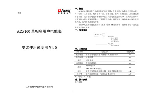
7.2.1 ADF100(计量型多用户电能表)
能同时计量 6 路有功电能,每路均能精确计量正负两个方向的电能,且以同
一方向累计;
具有实时功率显示功能,可实时显示用户的用电负荷;
088
ADF100 单相多用户电能表
一、概述
ADF100 单相多用户电能表是可同时计量 6 个单相用户的集中式智能电表。 可广泛用于工矿企业、城乡居民小区、学生公寓、农网、旧楼改造、高层建筑的 用电计量,适合于用电收费困难的单位以及流动性较强的用户(诸如商业房等)。 该表可以方便地实现远程集抄,预付费等功能,能有效防止各种偷漏电现象及用 电纠纷,为用电管理带来方便。
2
0022H
用户 4 功率因数 PF4
2
0023H
用户 5 功率因数 PF5
2
0024H
用户 6 功率因数 PF6
2
0025H
表号
2
0026H
波特率
2
0027H
密码
2
0028H
秒分
2
0029H
时星期
2
002AH 日月
2
002BH 年 保留
2
002CH 户号 1
2
002DH 户号 2
2
002EH 户号 3
001AH 用户 2 无功功率 Q2
2
001BH 用户 3 无功功率 Q3
2
001CH 用户 4 无功功率 Q4
2
001DH 用户 5 无功功率 Q5
DF型67系列多用户(智能)电能表使用说明书

山东科大中天电子有限公司
17
DF型多用户智能电能表系列产品使用说明书
十二、常见故障排除
1、户内没电 请先检查户内开关是否跳闸,如果没有跳闸检查电表下开关是否跳闸。
如果为预付费电表,检查一下该户电表是否有剩余电量,如果没有剩余 电量需要到物业处进行购电。如果还有剩余电量需要和物业处联系让物 业处通过售电机或计算机进行强制送电。(一开始安装完成通电后如果 发现个别有的出线没电,需要通过售电机进行强制送电) 2、户内实际负荷与对应的用电显示明显不一致。
DF型10(40)A 三回路型电能表,分户型式是2组三回路用户加2个三相用户加1个单相用 户,液晶显示 4. DF-60KF/2S+1D
DF型10(40)A 智能电能表,分户型式是个三相用户加1个单相用户
山东科大中天电子有限公司
5
DF型多用户智能电能表系列产品使用说明书
五、电能表外形及安装尺寸
DF型多用户智能电能表系列产品使用说明书
表二
单位范围条件 双绞电缆与电力电缆平行敷设
最小净距(mm)
380V <2kV.A
130
380V 2.5~5kV.A
300
380V >5Kv.A
600
有一方在接地的金属槽道或钢管中 70
150
300
双方均在接地的金属槽道或钢管中 注:
80
150
十一、电能表使用注意事项
1.使用前应详细阅读说明书。 2.严禁安装在露天位置。 3.送电前应检查空气开关或端子排与线路是否紧固,以免烧坏空气开 关、端子排引起安全事故。 4.送电后应检查用户线路应与表显户号是否一致,以免引起用户纠纷。 5.对电能表要设专人管理。 6.未经厂方许可,不可擅自打开电能表主机箱,否则后果自负。 7.保修一年,终生维修。
多功能集合式电表 DPM-C510 操作手册说明书

中达电通公司版权所有如有改动,恕不另行通知绵密网络 专业服务中达电通已建立了70余个分支机构及服务网点,并塑建训练有素的专业团队,提供客户最满意的服务,公司技术人员能在2小时内回应您的问题,并在48小时内提供所需服务。
400 - 820 - 9595沈阳电话:(024)2334-1160哈尔滨电话:(0451)5366-5568长春电话:(0431)8892-5060呼和浩特电话:(0471)6297-808北京电话:(010)8225-3225天津电话:(022)2301-5082济南电话:(0531)8690-6277太原电话:(0351)4039-485郑州电话:(0371)6384-2772石家庄电话:(0311)8666-7337上海电话:(021)6301-2827南京电话:(025)8334-6585杭州电话:(0571)8882-0610合肥电话 :(0551)6281-6777武汉电话:(027)8544-8475南昌电话:(0791)8625-5010成都电话:(028)8434-2075长沙电话:(0731)8549-9156重庆电话:(023)8806-0306 昆明电话:(0871)6313-7362广州电话:(020)3879-2175厦门电话:(0592)5313-601南宁电话:(0771)2621-501乌鲁木齐电话:(0991)4678-141兰州电话:(0931)6406-725西安电话:(029)8836-0780贵阳电话:(0851)8690-1374福州电话:(0591)8755-1305地址:上海市浦东新区民夏路238号邮编:201209电话:( 021 )5863-5678传真:( 021 )5863-0003网址: 扫一扫,关注官方微信DPM-093AM10-012021/11/01多功能集合式电表DPM-C510操作手册多功能集合式电表DPM-C510操作手册多功能控制型电表DPM-C510操作手册目录第1章产品概述1.1 序言.................................................................................... 1-2 1.2 外观及说明............................................................................ 1-2 1.3 警语与规范............................................................................ 1-3第2章规格说明2.1 电气规格 .............................................................................. 2-2 2.2 通讯规格 .............................................................................. 2-3 2.3 操作接口 .............................................................................. 2-42.3.1界面树形图....................................................................... 2-5 2.4 外观尺寸 .............................................................................. 2-6第3章安装说明3.1 安装方式 .............................................................................. 3-23.1.1安装环境 ......................................................................... 3-23.1.2注意事项 ......................................................................... 3-2 3.2 基本检测 .............................................................................. 3-4 3.3 接线说明 .............................................................................. 3-43.3.1线路接线图....................................................................... 3-43.3.2通讯特性 ......................................................................... 3-6第4章操作说明4.1 一般操作 .............................................................................. 4-24.1.1观看量测数据.................................................................... 4-2 4.2 设定操作 .............................................................................. 4-2i4.2.1 密码锁(PASS) .............................................................. 4-24.2.2 通讯站号设定(id)........................................................... 4-34.2.3 通讯波特率设定(bAUd)................................................... 4-34.2.4 同位设定(PRty) ............................................................ 4-34.2.5 系统设定(tyPE)............................................................. 4-34.2.6 一次侧比流器设定(Ct.PR)................................................ 4-44.2.7 比流器设定(Ct.SE) ........................................................ 4-44.2.8 重置设定(RSt).............................................................. 4-44.2.9 修改密码锁(Pwd) .......................................................... 4-54.2.10 电表信息(inFo)........................................................... 4-5第5章参数与功能5.1 参数一览表........................................................................... 5-25.2 Modbus通讯........................................................................ 5-65.2.1 支持的Modbus功能码....................................................... 5-65.2.2 Modbus通讯协议 ............................................................. 5-6第6章异常信息6.1 异常信息一览表...................................................................... 6-2附录A 配件A.1 DCTMC系列......................................................................... A-2A.2 DCTCS系列......................................................................... A-3A.3 DCT1000系列...................................................................... A-4A.4 DCT2000系列...................................................................... A-6 ii多功能控制型电表DPM-C510操作手册版本修订一览表版本变更内容发行日期第一版第一版发行2021/11/91第1章产品概述目录1.1 序言................................................................................... 1-2 1.2 外观及说明........................................................................... 1-2 1.3 警语与规范........................................................................... 1-31-1多功能控制型电表DPM-C510操作手册 1-2 1.1 序言感谢您使用本产品,本电表接口安装手册提供DPM-C510电表的相关信息。
DFSH1521型多用户集中式电能表

DFSH1521型多用户集中式电能表●防窃电●大容量●高性能●远程联网●数码显示泰安市宏达电子有限公司一、简介DFSH1521型多用户组合式电能表是公司研制生产的高科技产品,它采用微电子处理技术和SMT表面焊接及在线测试技术,能将多达36户单相用电和13户三相用电集中检测,逐户循环显示,并可将各户的用电量由红外抄表器采集或通过RS485接口实现计算机联网以及内刷卡售电功能。
传感元件采用了德国V AC真空熔炼公司研制的1J77A型高导磁率微型电流、电压互感器,与锰铜(或康铜)分流元件相比,具有精度高、量程范围宽、自身功耗低、抗干扰能力强等特点。
DFSH1521型多用户组合式电能表可广泛用于居民楼、集体公寓等用电场所,具有体积小、抄表方便和防窃电等功能,是老式机械电能表最理想的替代产品。
二、技术特点及参数1、技术特点(1)电表集中检测和显示,表箱体积小,抄表方便,防止窃电。
(2)高量程10—60A,用户无须因家用电器的增加而更换电表。
(3)实现远程联网,现场抄表。
(4)表壳冲压成形,密封性能好,符合国标GB/T17215—2002。
(5)电路采用三相电源供电。
即使供电线路缺相,也能正常计量。
(6)同时具备近程红外线抄表和远程计算机联网抄表功能。
(7)采用专用接线端子,双螺栓压线,使用更可靠。
(8)采用高精度微型电量互感器,电器隔离效果好,超负载能力强。
(9)整机功耗低,低于一台机械式电能表的功耗(<7V A)。
(10)远控型DFSH多户表具有计算机联网.刷卡带控制断送电功能,解决了电费收取难的问题。
2、技术参数(1)标定电流:10(60A);(2)工作电压:AC160V~250V(3)精度等级:2.0级;(4)环境温度:—20℃~55℃(5)0.4%Ib; (6)重量:约6kg(7) 总进线端子接线截面积:≤75mm(8) 用户接线端子接线截面积:≤100mm三.型号说明备注;控制型为DFSH 1521型为降低公用零线上的总电流,电能表总进线一般采用三相四线制接线方式,而用户接线方式可分为单相(D)或三相四线(T)。
- 1、下载文档前请自行甄别文档内容的完整性,平台不提供额外的编辑、内容补充、找答案等附加服务。
- 2、"仅部分预览"的文档,不可在线预览部分如存在完整性等问题,可反馈申请退款(可完整预览的文档不适用该条件!)。
- 3、如文档侵犯您的权益,请联系客服反馈,我们会尽快为您处理(人工客服工作时间:9:00-18:30)。
多用户电表的使用方法
多用户电表的使用方法
多用户电表是一种新型的电表,它可以实时监测多个用户的电量使用
情况,可以帮助用户更加有效、准确地控制电量消耗。
下面就来介绍
一下多用户电表的使用方法。
首先,您需要安装多用户电表。
安装时,需要根据电表说明书安装,
确保电表安装稳固。
安装完成后,您可以使用它检测多个用户的电量
使用情况,并可以进行智能管理。
其次,您可以使用多用户电表进行电量分配。
多用户电表可以进行电
量拆分,可以根据不同用户的用电情况,分配合理的电量,避免某些
用户因用电过多而影响到其他用户的用电。
最后,您可以使用多用户电表进行智能管理。
多用户电表可以对用户
的用电情况进行实时监测,并可以自动根据用户的用电情况调节电量,从而更加有效地控制用电,节省电费。
总的来说,多用户电表的使用方法比较简单,可以有效控制用户的用
电情况,节省电费,是一种非常实用的电表。