电磁流量转换器
电磁流量转换器

LDZ-50D型电磁流量转换器LDZ-50D型电磁流量转换器LDZ-50D型电磁流量转换器为智能型流量转换器,可与LD 型、LDC 型、LDQ 型电磁流量传感器配套使用、用于测量导电液体或液固两相介质的体积流量。
LDZ-50D型电磁流量转换器特点:1.采用微处理技术为核心智能化仪表。
采用低频方波励磁方式,测量稳定,工作可靠,测量精度高,抗干扰能力强。
2.流量测量范围宽,流速可在1m/s 至15m/s 范围设定。
全汉字大屏幕LCD 背光显示,在强光和无光的情况下均可清晰读数。
3.瞬时流量、累积流量、流速同时显示功能,具有双向流量自动测量功能。
4.具有停电计时,计次及时钟功能。
5.具有小信号切除和上、下限报警功能(接点输出)。
6.具有定量输出、单位脉冲输出,键控直接清零功能。
7.具有10位超长位数累积量显示(浮动小数点)和6 位瞬时量显示功能(浮动小数点)。
8.具有统一的直流信号和频率信号输出功能。
9.具有RS-232 或RS-485 通讯接口。
10.具有数据保存功能,可在长期停电情况下,保存所有数据。
11.具有互换性,传感器、转换器之间不必重新实流标定,仅利用4/1-2 位数字万用表就可实现他们之间的互换,因此方便现场安装和维修。
LDZ-50D型电磁流量转换器主要技术指标:1.精确度:±0.1%2.输入信号范围:0-0.2mVp-p 至0-2mVp-p6.25Hz 方波,对应传感器测量流速范围:0-1m/s 至0-15m/s。
3.输出信号:1. A.电隔离恒流源(4-20)m2. B.DC(负载电阻750Ω)3. C.10Hz-10KHz 脉冲宽度50μS4. D.单位脉冲,脉冲宽度为脉冲周期宽度的50%5. E.定量输出(1-999999)×单位6.F.RS232,RS485通讯接口累积流量显示位数:十位瞬时流量显示位数:六位供电电源:110V-265V.AC(45-63)Hz24V.DC环境温度:-10℃至+50℃相对湿度:5%-90%功耗:与传感器配套小于20VAPS:开封利源流量计有限公司(原开封流量计厂)是有着三十多年专业生产流量仪表历史的厂家,现已成为产品结构合理,国内品种最全的流量仪表生产基地。
科隆电磁流量计转换器快速操作手册
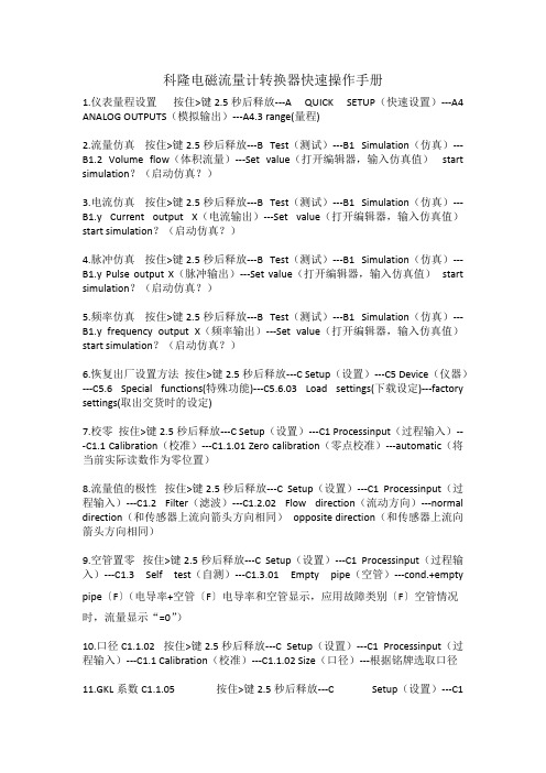
科隆电磁流量计转换器快速操作手册1.仪表量程设置按住>键2.5秒后释放---A QUICK SETUP(快速设置)---A4 ANALOG OUTPUTS(模拟输出)---A4.3 range(量程)2.流量仿真按住>键2.5秒后释放---B Test(测试)---B1 Simulation(仿真)---B1.2 Volume flow(体积流量)---Set value(打开编辑器,输入仿真值)start simulation?(启动仿真?)3.电流仿真按住>键2.5秒后释放---B Test(测试)---B1 Simulation(仿真)---B1.y Current output X(电流输出)---Set value(打开编辑器,输入仿真值)start simulation?(启动仿真?)4.脉冲仿真按住>键2.5秒后释放---B Test(测试)---B1 Simulation(仿真)---B1.y Pulse output X(脉冲输出)---Set value(打开编辑器,输入仿真值)start simulation?(启动仿真?)5.频率仿真按住>键2.5秒后释放---B Test(测试)---B1 Simulation(仿真)---B1.y frequency output X(频率输出)---Set value(打开编辑器,输入仿真值)start simulation?(启动仿真?)6.恢复出厂设置方法按住>键2.5秒后释放---C Setup(设置)---C5 Device(仪器)---C5.6 Special functions(特殊功能)---C5.6.03 Load settings(下载设定)---factory settings(取出交货时的设定)7.校零按住>键2.5秒后释放---C Setup(设置)---C1 Processinput(过程输入)---C1.1 Calibration(校准)---C1.1.01 Zero calibration(零点校准)---automatic(将当前实际读数作为零位置)8.流量值的极性按住>键2.5秒后释放---C Setup(设置)---C1 Processinput(过程输入)---C1.2 Filter(滤波)---C1.2.02 Flow direction(流动方向)---normal direction(和传感器上流向箭头方向相同)opposite direction(和传感器上流向箭头方向相同)9.空管置零按住>键2.5秒后释放---C Setup(设置)---C1 Processinput(过程输入)---C1.3 Self test(自测)---C1.3.01 Empty pipe(空管)---cond.+empty pipe〔F〕(电导率+空管〔F〕电导率和空管显示,应用故障类别〔F〕空管情况时,流量显示“=0”)10.口径C1.1.02 按住>键2.5秒后释放---C Setup(设置)---C1 Processinput(过程输入)---C1.1 Calibration(校准)---C1.1.02 Size(口径)---根据铭牌选取口径11.GKL系数C1.1.05 按住>键2.5秒后释放---C Setup(设置)---C1Processinput(过程输入)---C1.1 Calibration(校准)---C1.1.05 GKL---根据铭牌设定数值12.磁场频率(Field frequency)C1.1.13 按住>键2.5秒后释放---C Setup(设置)---C1 Processinput(过程输入)---C1.1 Calibration(校准)---C1.1.1 Zero calibration(零点校准)---C1.1.13 Field frequency(磁场频率)---13.电流输出开启(Current output)C2.1.1 按住>键2.5秒后释放---C Setup(设置)---C2 I/O(输入/输出)---C2.1 Hardware(硬件)---C2.1.1 Terminals A(端子A)---Current output(电流输出开启)/Off(电流输出关闭,该端子无任何功能)14.频率输出开启(Frequency output)C2.1.4 按住>键2.5秒后释放---C Setup(设置)---C2 I/O(输入/输出)---C2.1 Hardware(硬件)---C2.1.1 Terminals A(端子A)---C2.1.4 Terminals D(端子D)---Frequency output (频率输出)/Pulse output (脉冲输出)/Status output (状态输出开启)/Limit switch(限位开关开启)/Off(关闭,该端子无任何功能)15.量程(Range)C2.2.6 按住>键2.5秒后释放---C Setup(设置)---C2 I/O(输入/输出)---C2.2 Current output A(c2.2=A C2.3=B C2.4=C)---C2.2.1 Range 0%-100%(电流输出量程,例如4-20MA)---C2.2.6 Range(量程)---测量范围为0%-100%16.极性(Polarity)C2.2.7 按住>键2.5秒后释放---C Setup(设置)---C2 I/O(输入/输出)---C2.2 Current output A(c2.2=A C2.3=B C2.4=C)---C2.2.1 Range 0%-100%(电流输出量程,例如4-20MA)---C2.2.7 Polarity(极性)---Both polarities (使用正、负数值)/Positive polarity (用正值,负值用力0%代替)/Negative polarity (用负值,正值用0%代替)/Absolute value(用测量值的绝对值作为电流输出)17.指示流量传感器的衬里材料(Liner)C1.4.1 按住>键2.5秒后释放---C Setup(设置)---C1 Process input(过程输入)---C1.1 Calibraton(校准)---C1.4 Information(所有传感器的电子信息)---C1.4.1 Liner (指示流量传感器的衬里材料)---PTFE(聚四氟已稀)、PFA(衬里)、NEOPRENE(氯丁橡胶)、POLYURETHANE(聚氨酯橡胶)18.指示电极材料(Eletr.material)C1.4.1 按住>键2.5秒后释放---C Setup(设置)---C1 Process input(过程输入)---C1.1 Calibraton(校准)---C1.4 Information(所有传感器的电子信息)---C1.4.2 Electr.material (指示传感器电极材料)---MO2TI、HC、HB、TI、TA、PT19.在测量页中打开累加器(1ST meas.page 1)C5.3 按住>键2.5秒后释放---C Setup(设置)---C1 Process input(过程输入)---C5 Device(设备)---C5.3 1st meas.page 1(第一测量显示屏)---C5.3.8 measurement 2nd line (第二测量行)---counter1(在Profibus 中为FB2累加器)20.在测量页2中打开电导率测量(2ST meas.page 2)C5.3 按住>键2.5秒后释放---C Setup(设置)---C1 Process input(过程输入)---C5 Device(设备)---C5.4 2nd meas.page 2(第一测量显示屏)---C5.4.8 measurement 1st line (第一测量行)---conductivity(电导率)。
VersaFlow TWM 9000 电磁流量转换器说明书

VersaFlow TWM 9000 Electromagnetic Flow Converter Specifications34-VF-03-02 September 2015The High-Performance SolutionThe TWM 9000 is the only electromagnetic flow converter with diagnostics for the instrument and application. TWM 9000 is compatible with all electromagnetic flow sensors and is suitable for all applications.Highlights•Complete Diagnostics of the application and instrument •Quick to install and easy to operate•Excellent long-term stability•Optimal zero point stability independent from process properties•One converter for all applications; helps facilitate procurement, engineering and inventory management. •Exceeds requirements VDI / VDE/ WIB 2650 and NAMUR NE 107•Integrated temperature and conductivity measurement •Suitable for Custody TransferIndustries•Chemicals•Food & Beverage•Minerals & Mining•Oil & Gas•Pharmaceuticals•Power Plants•Pulp & Paper•Water•Wastewater•MachineryFigure 1 – VersaFlow Electromagnetic Flow ConverterElectromagnetic Product RangeVersaFlow converters are compatible with all sensorsAll meters consist of a sensor and a converter. Theconverter may be mounted integral to the sensor, or remotely, either with a field mounting kit or a wall-mounted housing. See sensor specification for details.Applications•Products with low conductivity, high solid contents or entrained air•Inhomogeneous, abrasive and corrosive products •Quick media changes•Abrupt changes of pH value•Pulsating or turbulent flowsModelC (compact) (Integrally Mounted) TWM 9000 CF (field), W (wall), R (19" rack) (Remote Mounted) TWM 9000 F, TWM 9000 W, TWM 9000 RPerformanceMaximum measuring error See Accuracy CurvesRepeatability ±0.06% to OIML R117Full-scale range (see flow table) v = 0.3...12 m/s / 1...40 ft/sConductivityMin. process liquid conductivity (non-water) As low as 1 µS/cm (see flow sensor ) Min. process liquid conductivity (water) 20 µS/cmContent of solidsMaximum percentage (by volume) 30%DisplayWith local display (2 meas. pages: 1 status page, 1 graphical page) StandardLanguagesEnglish, French, German, Dutch, Polish, Portuguese, Danish ,StandardSpanish, Swedish, Slovenian, ItalianCombinationsVersaFlow Mag 100 Specification 34-VF-03-08 DN10...150 (3/8” to 6”)VersaFlow Mag 1000 Specification 34-VF-03-16 DN25...3000 (1” to 120”)VersaFlow Mag 4000 Specification 34-VF-03-01 DN2.5...3000 (1/10” to 120”)VersaFlow Mag 2000 Specification 34-VF-03-21(F), 34-VF-03-22(SW) DN2.5...250 (1/10” to 10”)VersaFlow Mag 3000 Specification 34-VF-03-23 DN2.5...150 (1/10” to 6”)CommunicationCurrent, pulse & status output, frequency output, limit switch StandardHART communication, control input, 3 counters StandardEx-i OptionFoundation Fieldbus OptionModbus OptionVerificationIntegrated verification, diagnostics: Standard- instrument / process / measurement Standard- empty pipe indication / stabilization StandardCustody TransferWithout StandardCold potable water (OIML R-49, KIWA K618) Option1Other than water (OIML R-117) Option1Power SupplyVoltage Power Consumption Standard/Option 100…230 VAC (-15% / +10%), 50/60 Hz 22 VA Standard24 VDC (-55% / +30%) 12 W Option24 VAC/DC (AC: -15% / +10%; DC: -25% / +30%) AC 22 VA; DC: 12 W OptionApprovalNon Ex StandardEEx - zone 1 Option 2FM - Class I DIV 2 Option 2CSA - Class I DIV 2 Option 2NEPSI zone 1 Option 2SAA – Aus Ex zone 1 / 2 (pending) Option 2Protection category (according to IEC 529 / EN 60 529)C (compact) IP 66 / 67 (eq. to NEMA 6)F (remote) IP 66 / 67 (eq. to NEMA 6)W (wall) IP 65 (eq. to NEMA 4/4X)R (19" rack) IP 20 (eq. to NEMA 1)TemperatureProcess temperature See flow sensorAmbient temperature -40…+65°C / -40…+149°FStorage temperature -50…+70°C / -58…+158°FSignal CableSeparate - DS (dep. on measuring sensor and conductivity) 5...600 m / 15...1950 ftSeparate - BTS (dep. on measuring sensor and conductivity) 5...600 m / 15...1950 ftSeparate - LIYCY (Class 1 Div. 2 only) (dep. on measuring sensor and5...100 m / 15...330 ftconductivity)1pending2only for C and F versionCable ConnectionM20 x 1.5 Standard ½" NPT Option PF ½ OptionMaterials UsedDie-cast aluminum (polyurethane coated); C and F version only Standard Polyamide - polycarbonate; W version only Standard Stainless steel 316 L (1.4404); C and F version only Option Custody transfer lead & sealing; C and F version only Option 11 pendingDimensions and Weights1 Compact version (TWM 9000 C)2 Field housing (TWM 9000 F) - remote version3 Wall-mounted housing (TWM 9000 W) - remote version4 19" rack (TWM 9000 R) - remote versionDimensions and Weights in mm and kgVersionDimensions mm [inches]Weights kg[lbs]ab c d e fghTWM 9000 C 202 (7.95) 120 (4.75) 155 (6.10) 260 (10.20)137 (5.40)---4.2 (9.30) TWM 9000 F 202 (7.95) 120 (4.75) 155 (6.10) - - 140.5 (5.50) 295.8 (11.60) 277 (10.90) 5.7 (12.60) TWM 9000 W 198 (7.80) 138 (5.40) 299 (11.80) - - - - - 2.4 (5.30) TWM 9000 R142 (5.60)129 (5.08)195 (7.68)--140.5 (5.53)295.8 (11.65)277 (10.90)1.2 (2.65)I/O SpecificationsOverall FunctionalityFunction Continuous measurement of actual volume flow rate, flow velocity, conductivity,massflow (at const. density), coil temperature. Integrated batch controllerBidirectional flow measurement and totalisationFlow direction identified via status or current outputDiagnostics: Accuracy, linearity, electrode contamination, noise, flow profile, fieldcurrent, coil resistance and temperature, empty or non-full pipe + derived functionsCurrent OutputFunction Measurement of volume and mass (at constant density), HART® communication Settings With HART®Without HARTQ = 0%: 4…15 mA Q = 0%: 0…15 mAQ = 100%: 10…21.5 mA Q = 100%: 10…21.5 mAError identification: 3.5…22 mA Error identification: 0…22 mA Operating data Basic I/Os Modular I/Os EEx-iActive Uint,nom = 24 VDCI ≤ 22 mARL ≤ 1 kΩUint,nom = 20 VDCI ≤ 22 mAR L≤ 450 ΩU0 = 21 VI0 = 90mAP0 = 0.5WC0 = 90 nF / L0 = 2 mHC0 = 110 nF / L0 = 0.5mHPassive Uext ≤ 32 VDCI ≤ 22 mAU0 ≤ 1.8 V at I = 22 mA Uext = 32 VDCI ≤ 22 mAU0≤ 4 V at I = 22 mA U i = 30 VI i = 100 mAP i= 1WC i = 10 nFL i ~ 0 mHPulse or Frequency OutputFunction Can be set as a pulse output (e.g.- for volume or mass counting) or frequency output Settings For Q = 100%: 0.01...10000 pulses per second or pulses per unit volumePulse width: setting automatic, symmetric or fixed (0.05...2000 ms)Operating data Basic I/Os Modular I/Os EEx-iActive-U nom = 24 VDC-f max ≤100 Hz:I ≤20 mAopen: I ≤0.05 mAclosed:U0,nom = 24 V at I = 20 mA100 Hz < f max ≤10 kHz:I ≤20 mAopen: I ≤0.05 mAclosed:U0,nom = 22.5 V at I = 1 mAU0,nom = 21.5 V atI = 10mAU0,nom = 19 V at I = 20 mAPassive U ext ≤32 VDC -f maxδ100 Hz:I ≤100 mAopen:I ≤0.05 mA at U ext = 32 VDCclosed:U0 ≤0.2 V at I = 10 mAU0 ≤2 V at I = 100mA100 Hz < f max δ10 kHz:I ≤20 mAopen:I ≤0.05 mA at U ext = 32 VDCclosed:U0 ≤1.5 V at I = 1 mAU0 ≤2.5 V at I = 10 mAU0 ≤5.0 V at I = 20 mANAMUR-Passive to EN 60947-5-6open: I nom = 0.6mAclosed: I nom = 3.8mA Passive to EN 60947-5-6open: I nom = 0.43 mA closed: I nom = 4.5mA U i = 30 VI i = 100 mAP i = 1 WC i =10 nFL i ~ 0 mHStatus Output/Limit SwitchFunction and settings Settable as automatic measuring range change, indicator for direction of flow, overflow,error, operating point or empty pipe detectionValve control with activated dosing functionStatus and/or control: ON or OFFOperating data Basic I/Os Modular I/Os EEx-iActive - U int = 24 VDCI ≤20 mAopen: I ≤0.05 mAclosed:U0,nom = 24 V at I = 20 mA-Passive Uext ≤32 VDCI ≤100 mAopen:I ≤0.05 mA atUext = 32 VDCclosed:U0 ≤0.2 V at I = 10 mAU0 ≤2 V at I = 100mA U ext = 32 VDCI ≤100 mAR L≤47 k∧open:I ≤0.05 mA atU ext = 32 VDCclosed:U0≤0.2 V at I = 10 mAU0≤2 V at I = 100 mA-NAMUR - Passive to EN 60947-5-6open: I nom = 0.6 mAclosed: I nom = 3.8mA Passive to EN 60947-5-6 open: I nom = 0.43 mA closed: I nom = 4.5mAU i = 30 VI i = 100 mAP i = 1 WC i =10 nFL i = 0 mHControl InputFunction Hold value of the outputs (e.g. for cleaning counter and error reset, range change).Start of dosing when dosing function is activated.Operating data Basic I/Os Modular I/Os EEx-i Active-U int = 24 VDCTerminals open:U0,nom = 22 VTerminals bridged:I nom = 4 mAOn:U0 ≥12 V withI nom = 1.9mAOff:U0 ≤10 V withI nom = 1.9mA-Passive U ext ≤32 VDCI nom = 6.5 mAat U ext = 24 VDCI nom = 8.2 mAat U ext = 32 VDCOn: U0 ≥8 Vwith I nom = 2.8mAOff: U0 ≤2.5 Vwith I nom = 0.4mA U ext ≤32 VDCI ≤9.5 mA at U ext = 24 VI ≤9.5 mA at U ext = 32 VOn:U0 ≥3 V with I nom = 1.9mAOff:U0 ≤2.5 Vwith I nom = 1.9mAU ext δ 32 VDCI ≤6 mA at U ext = 24VI ≤6.6 mA at U ext =32 VOn:U0 ≥5.5 V or I ≥4mAOff:U0 ≤3.5 V or I ≤0.5mAU i = 30 VI i = 100 mAP i = 1 WC i = 10 nFL i = 0 mHNAMUR-Active to EN 60947-5-6Terminals open:U0,nom = 8.7 VTerminals bridged:I nom = 7.8 mAOn/off: U0, nom = 6.3 Vwith I nom = 1.9 mAIdentification for openterminals:U0 ≥8.1 V with I ≤0.1 mAIdentification for bridgedterminals:U0 ≤1.2 V with I ≥6.7 mA-Low Flow Cut-OffOn 0...±9.999 m/s; 0...20.0%, settable in 0.1% steps, separately for each current and pulse output Off 0...±9.999 m/s; 0...19.0%, settable in 0.1% steps, separately for each current and pulse outputTime ConstantFunction Can be set together for all flow indicators and outputs, or separately for: current, pulse and frequency output, and for limit switches and the 3 internal counters Time setting0…100 seconds, settable in 0.1 second stepsI/O-Module Combination PossibilitiesCommunicationB a s i c I /OE x -i I /O M o d u l a r I /OCurrent OutputActive / passive HARTPulse and Status OutputActive PassiveNamur (acc. to EN 60947-5-6)Control InputActive PassiveNamur (acc. to EN 60947-5-6)Foundation FieldbusFoundation Fieldbus (pending)ModbusModbusProtectionEx-d / estandard optional on requestNote:Ex-i I/O: up to 1 additional in-/output module possible (see I/O-module combinations) Modular I/O: up to 2 additional in-/output module possible (see I/O-module combinations)I/O ModulesI/O1st module2nd module1Basic0no module possible0no module possible2Ex-i (Ia + Pp)1Ex-i (Ia + Pp/Cp)3Ex-i (Ip + Pp)2Ex-i (Ip + Pp/Cp)4Modular (Ia + Pa)8no module8no module6Modular (Ia + Pp)A Ia A Ia Ia = current output - active7Modular (Ia + Pn)B Ip B Ip Ip = current output - passive 8Modular (Ip + Pa)C Pa/Sa C Pa/Sa Pa/Sa = pulse/status output -active, high currentB Modular (Ip + Pp)E Pp/Sp E Pp/Sp Pp/Sp = pulse/status output -passive, high currentC Modular (Ip + Pn)F Pn/Sn F Pn/Sn Pn/Sn = pulse/status output -passive, NamurE Foundation Fieldbus H Cn H Cn Cn = control input - active,NamurG RS485 ModbusH RS485 Modbus withinteractive terminationThe TWM 9000 with standard basic I/O covers almost all applications, having 4 I/Os:•active/passive current output (+HART)•passive pulse/status output•passive status output•passive status output / control inputThe I/O-module combination is thus 1-0-0 (see above).The TWM 9000 with modular I/O can be tailor-made to any application:•Suppose you require a converter with passive pulse output and 3 passive current outputs. The I/O-module combination then becomes B-B-B.•Suppose you require a converter with 2 active pulse/status outputs. The I/O-module combination then becomes either 4-C-8 or 8-C-8 (depending on whether active or passive current output is required). The latter ’8’ indicates that1 additional module can be added in the future.For I/O-module combinations, not described in the overview on the right, please consult HONEYWELL.Example for Combination of I/O’sBasic I/O2 3 1 0 0Modular I/OModular I/OModular I/OModular I/OComm 1st 2nd Comm 1st 2nd Comm 1st 2nd Comm 1st 2nd4 8 8 6 8 8 7 8 8 8 8 8 A 8 A 8 A 8 B 8 A A A B C E F C G K H G C 8 E 8 F 8 C 8 C E F C G K H G G 8 K 8 H 8 G 8GKHGD 8 8E 8 8 G 8 8 H 8 8 A 8 A 8 A 8 A 8 A A A A C C C C K K K K C 8 C 8 C 8 C 8 C C C C K K K K K 8 K 8 K 8 K 8KKKKB 8 8C 8 8 F8 0 B 8 B 8 A 0 B B B 0 E F C 0 K H E 0 E 8 F 8 F 0 E F G 0 K H H 0 K 8 H 8 KKHEx- I/O 1 2 3 2 0 0 1 2 3 0 0 1 2 D 0 0 1 2 E 0 0 12Full-Scale FlowratesFlowrates in m/s and m 3/hQ 100% in m 3/hv [m/s]0.3312DN [mm] minimumnominalmaximum2.5 0.01 0.05 0.21 4 0.01 0.14 0.54 6 0.03 0.31 1.22 10 0.08 0.853.39 15 0.19 1.91 7.63 20 0.34 3.39 13.57 25 0.53 5.30 21.21 32 0.87 8.69 34.74 40 1.36 13.57 54.29 50 2.12 21.21 84.82 65 3.58 35.84 143.35 80 5.43 54.29 217.15 100 8.48 84.82 339.29 125 13.25 132.54 530.15 150 19.09 190.85 763.40 200 33.93 339.30 1357.20 250 53.01 530.13 2120.52 300 76.34 763.41 3053.64 350 103.91 1039.08 4156.32 400 135.72 1357.17 5428.68 450 171.77 1717.65 6870.60 500 212.06 2120.58 8482.32 600 305.37 3053.70 12214.80 700 415.62 4156.20 16624.80 800 542.88 5428.80 21715.20 900 687.06 6870.60 27482.40 1000 848.22 8482.20 33928.80 1200 1221.45 12214.50 48858.00 1400 1433.52 14335.20 57340.80 1600 2171.46 21714.60 86858.40 1800 2748.27 27482.70 109930.80 2000 3393.00 33930.00 135720.00 2200 4105.50 41055.00 164220.00 2400 4885.80 48858.00 195432.00 2600 5733.90 57339.00 229356.00 2800 6650.10 66501.00 266004.00 30007634.1076341.00305364.00Flowrates in ft/s and gallons/minQ 100% in US gallons/minv [ft/s] 1 10 40 DN [inch]minimumnominalmaximum1/10 0.02 0.23 0.93 1/8 0.06 0.60 2.39 1/4 0.13 1.34 5.38 3/8 0.37 3.73 14.94 1/2 0.84 8.40 33.61 3/4 1.49 14.94 59.76 1 2.33 23.34 93.36 1.25 3.82 38.24 152.97 1.5 5.98 59.75 239.02 2 9.34 93.37 373.47 2.5 15.78 159.79 631.16 3 23.90 239.02 956.09 4 37.35 373.46 1493.84 5 58.35 583.24 2334.17 6 84.03 840.29 3361.17 8 149.39 1493.29 5975.57 10 233.41 2334.09 9336.37 12 336.12 3361.19 13444.77 14 457.59 4574.93 18299.73 16 597.54 5975.44 23901.76 18 756.26 7562.58 30250.34 20 933.86 9336.63 37346.53 24 1344.50 13445.04 53780.15 28 1829.92 18299.20 73196.79 32 2390.23 23902.29 95609.15 36 3025.03 30250.34 121001.37 40 3734.50 37346.00 149384.01 48 5377.88 53778.83 215115.30 56 6311.60 63115.99 252463.94 64 9560.65 95606.51 382426.03 72 12100.27 121002.69 484010.75 80 14938.92 149389.29 597557.18 88 18075.97 180759.73 723038.90 96 21511.53 215115.30 860461.20 104 25245.60 252456.02 1009824.08 112 29279.51 292795.09 1171180.37 12033611.93336119.311344477.23AccuracyReference conditions Medium: WaterTemperature: 20°C / 68°F Pressure: 1 bar / 14.5 psi Inlet: ≥ 5DNVersaFlow versionDN [mm]DN [inches]AccuracyCurveMag 200010….100 3/8…10 0.15% of MV + 1 mm/s 1 Mag 1000, 3000, 4000 10….1600 3/8…80 0.2% of MV + 1 mm/s 2 Mag 100 10…150 3/8…6 0.3% of MV + 2 mm/s 3 Mag 1000, 4000 >1600 >64 0.3% of MV + 2 mm/s 3 Mag 2000, 3000, 4000<10<3/80.3% of MV + 2 mm/s3For More InformationLearn more about how Honeywell’s VersaFlow TWM 9000 Electromagnetic Flow Converter can help facilitate procurement, engineering and inventory management, visit our website /ps/hfs or contact your Honeywell account manager.Honeywell Process Solutions 1860 West Rose Garden Lane Phoenix, Arizona 85027Tel: 1-800-423-9883 or 1-800-343-0228 /psSpecifications are subject to change without notice.34-VF-03-02September, 2015© 2015 Honeywell International Inc.。
E--mag转换器操作说明
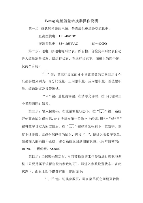
E-mag电磁流量转换器操作说明第一步: 确认转换器的电源,是直流供电还是交流供电,直流型供电:11~40V.DC交流型供电:85~265V.AC 45~400Hz 第二步:通电,接通电源后仪表开始自检,自检完毕后仪表自动进入流量测量状态,即运行状态,在运行状态下,面板上的四个键,仅两个有用:“”键:第三行显示的6个只读参数的切换显示6个只读参数分别为:百分比流量、正向累积量、反向累积量、差值累积量、流速测试及报警测试。
“▽”键:总量清零键,在清零允许时,按下此键对三个累积两同时清零。
第三步:输入保密码。
在流量测量状态下,按“”键,系统开始要求输入保密码,此时光标在第一位数字上闪烁。
用“△”或“▽”键将数字设定为所需值后,按“”键移动光标到下一位数字。
重复上述步骤,完成全部码值的输入,再按“”、键进入参数子菜单。
如果输入的码值不正确,那么系统返回到测量状态。
(用户级密码:10760;工程师级:56360)第四步:当保密码确定后,可对转换器的工作参数进行选取与调整(只要是属于该保密级的参数均可),即进入参数设置状态,在此状态下,面板上四个键都有用,作用如下:“”键:切换参数页,即在菜单页之间翻页转换;“”键:切换参数项,即在菜单页中参数项之间的转换,即确认参数值。
“▽”键:改变参数值(减小)。
“△”键:改变参数值(增加)。
参数的含义和取值应当正确理解,详细请见说明书P40~P44。
第五步:返回至运行状态。
当参数设置完成后,无论在任何一菜单项中,只要用户按下“”键五秒钟,然后再松开,就会退出菜单系统返回到流量测量状态,即运行状态。
开封仪表厂售后服务处2003.4.28。
LDZ-5 电磁流量转换器 说明书

LDZ-5 电磁流量转换器一、概述LDZ-5型电磁流量转换器与各种规格的电磁流量传感器配套组成电磁流量计,对导电液体或液固两相流体的体积流量进行测量。
广泛应用于化工、造纸、食品、污水测量等领域。
转换器将来自传感器的毫伏级流量信号转换成与流量成正比的0~10mA DC或4~20mA DC标准信号输出,显示瞬时流量和累计总量。
其主要特点是:·仪表测量范围大,工作稳定可靠:·能显示瞬时流量和累计总量:·具有断电保护功能:·特殊订货可定量控制。
二、主要技术指标输入信号:mV级三值矩形波输出信号:0~10mA DC(负载电阻O~1kΩ)4~20mA DC(负载电阻0~1kΩ)0~10kHz(特殊定货)精度等级:0.3级励磁电流:200±O.2mA电 源:220V 50Hz12V DC、24V DC或电瓶供电(特殊订货)断电保持时间:不少于1年环境条件:温度-10~+50℃相对湿度<85%重 量:约5kg三、工作原理由转换器励磁电波发生器产生的励磁电流,经传感器励磁线圈产生电磁场.当被测介质测量导管,垂直切割磁力线时,在导管两侧的电极上量感应产生与流速成正比的微小三值矩形波电压信号,该信号由转换器的信号放大器处理成直流电压,经V/f电压-频率转换器换成与流速成正比的频率信号,输入8031单片微机系统,实现标准电流输出、瞬时流量、累计总量显示.定量控制等功能.口外形及安装尺寸安装与使用·现场墙挂式安装;·安装位置应避免与大电机相邻,机壳应接地良好;·转换器与传感器之间导线连接距离一般为10~30m,大于30m时请在订货时注明;·当需要变更转换器时,只需把系数拨盘上的仪表系数拨到与传感器铭牌上标明的传感器系数相一致,即可实现互换:·当需要变更仪表量程时,可按使用说明书上方法重新设置仪表系数。
科隆IFC300智能电磁流量转换器手册(E)概要

Signal converter for electromagnetic flowmetersIFC 300All rights reserved. It is prohibited to reproduce this documentation, or any part thereof, withoutthe prior written authorisation of KROHNE Messtechnik GmbH & Co. KG.Subject to change without notice.2 11/2007 • 4000069801 - MA IFC 300 R02 enCopyright 2007 by KROHNE Messtechnik GmbH & Co.KG - Ludwig-Krohne-Straße 5 - 47058Duisburg: IMPRINT3 11/2007 • 4000069801 - MA IFC 300 R02 en 1 Safety instructions (61.1Safety instructions from the manufacturer (61.1.1Copyright and data protection (61.1.2Disclaimer (61.1.3Product liability and warranty (71.1.4Information concerning the documentation (71.1.5Display conventions...................................................................................................81.2Safety instructions for the operator (82)Instrument description..................................................................92.1Scope of delivery..................................................................................................92.2Instrument description.. (102.2.1Field housing (112.2.2Wall-mounted housing (122.3Nameplates........................................................................................................132.3.1Compact version (example. (132.3.2Remote version (example (142.3.3Electrical connection data of the I/Os (example of basic version (153)Installation.. (163.1Notes on installation..........................................................................................163.2Storage...............................................................................................................163.3Installation specifications..................................................................................163.4Transport............................................................................................................173.5Mounting of the compact version......................................................................173.6Mounting the field housing, remote version .. (183.6.1Pipe mounting (183.6.2Wall mounting (193.6.3Rotating the display of the field housing version (203.7Mounting the wall-mounted housing, remote version......................................213.7.1Pipe mounting. (213.7.2Wall mounting..........................................................................................................224 Electrical connections.. (234.1Safety instructions.............................................................................................234.2Important notes on electrical connection.........................................................234.3Electrical cables for remote device versions, notes.. (244.3.1Notes on signal cables A and B (244.3.2Notes on field current cable C (244.3.3Using other signal cables (254.4Preparing the signal and field current cables...................................................264.4.1Signal cable A (type DS 300, construction .(264.4.2Preparing signal cable A, connection to signal converter (27CONTENTS4 11/2007 • 4000069801 - MA IFC 300 R02 en4.4.3Length of signal cable A..........................................................................................314.4.4Signal cable B (type BTS 300, construction..........................................................324.4.5Preparing signal cable B, connection to signal converter......................................334.4.6Length of signal cable B..........................................................................................374.4.7Preparing field current cable B, connection to signal converter...........................384.4.8Prepare signal cable A, connect to measuring sensor...........................................394.4.9Prepare signal cable B, connect to measuring sensor (414.4.10Preparing field current cable C, connection to measuring sensor (434.5Connecting the signal and field current cables (444.5.1Connecting the signal and field current cables, field housing (454.5.2Connecting the signal and field current cables, wall-mounted housing (464.5.3Connection diagram for measuring sensor, field housing (474.5.4Connection diagram for measuring sensor, wall-mounted housing (484.6Grounding the measuring sensor......................................................................494.6.1Classical method.. (494.6.2Virtual reference......................................................................................................494.7Connect power, all housing variants.................................................................504.8Inputs and outputs, overview.. (524.8.1Combinations of the inputs/outputs (I/Os (524.8.2Fixed, non-alterable input/output versions (544.8.3Alterable input/output versions (564.9Description of the inputs and outputs...............................................................584.9.1Current output (584.9.2Pulse and frequency output (594.9.3Status output and limit switch (604.9.4Control input............................................................................................................614.10Electrical connection of the inputs and outputs (614.10.1Field housing, electrical connection of the inputs and outputs (624.10.2Wall-mounted housing, electrical connection of the inputs and outputs (634.10.3Laying electrical cables correctly (644.11Connection diagrams of inputs and outputs (654.11.1Important notes (654.11.2Description of the electrical symbols (664.11.3Basic inputs/outputs (674.11.4Modular inputs/outputs and bus systems (704.11.5EExi inputs/outputs (774.11.6HART ® connection (815 Start-up (835.1Switching on the power......................................................................................835.2Starting the signal converter.. (83 11/2007 • 4000069801 - MA IFC 300 R02 en 6 Operation (846.1Display and operator input elements (846.1.1Using an IR interface (856.1.2Time-out functions (856.1.3Display in measuring mode (866.1.4Display for selection of menu and functions (866.1.5Display for setting of data and functions (876.1.6Display after change of data and functions.............................................................876.2Program structure.............................................................................................886.3Function tables ..(906.3.1Menu A, quick setup (906.3.2Menu B, test (926.3.3Menu C, setup (936.3.4Set free units (1096.3.5Reset counter in Quick Setup menu (1106.3.6Deleting error messages in the Quick Setup menu..............................................1106.4Status messages and diagnostic information (1117)Service.......................................................................................1177.1Spare parts availability....................................................................................1177.2Availability of services......................................................................................1177.3Returning the device to the manufacturer (1187.3.1General information (1187.3.2Form (for copying to accompany a returnedinstrument ....................................1197.4Disposal (1198)Technical data ...........................................................................1208.1Technical data..................................................................................................1208.2Flow tables.......................................................................................................1268.3Accuracy...........................................................................................................1298.4 Dimensions and weights. (1308.4.1Housing (1308.4.2Mounting plate, field housing (1318.4.3Mounting plate, wall-mounted housing (1329)KROHNE Product Overview. (13611.1 Safety instructions from the manufacturer1.1.1 Copyright and data protectionThe contents of this document have been created with great care. Nevertheless, we provide noguarantee that the contents are correct, complete or up-to-date.The contents and works in this document are subject to German copyright. Contributions fromthird parties are identified as such. Reproduction, processing, dissemination and any type of usebeyond what is permitted under copyright requires written authorisation from the respectiveauthor and/or the manufacturer.The manufacturer tries always to observe the copyrights of others, and to draw on works createdin-house or works in the public domain.The collection of personal data (such as names, street addresses or e-mail addresses in themanufacturer's documents is always on a voluntary basis whenever possible. Wheneverfeasible, it is always possible to make use of the offerings and services without providing anypersonal data.We draw your attention to the fact that data transmission over the Internet (e.g. whencommunicating by e-mail may involve gaps in security. It is not possible to protect such datacompletely against access by third parties.We hereby expressly prohibit the use of the contact data published as part of our duty to publishan imprint for the purpose of sending us any advertising or informational materials that we havenot expressly requested.1.1.2 DisclaimerThe manufacturer will not be liable for any damage of any kind by using its product, including,but not limited to direct, indirect, incidental, punitive and consequential damages.This disclaimer does not apply in case the manufacturer has acted on purpose or with grossnegligence. In the event any applicable law does not allow such limitations on implied warrantiesor the exclusion of limitation of certain damages, you may, if such law applies to you, not besubject to some or all of the above disclaimer, exclusions or limitations.Any product purchased from the manufacturer is warranted in accordance with the relevantproduct documentation and our Terms and Conditions of Sale.The manufacturer reserves the right to alter the content of its documents, including thisdisclaimer in any way, at any time, for any reason, without prior notification, and will not be liablein any way for possible consequences of such changes.11.1.3 Product liability and warrantyThe operator shall bear responsibility for the suitability of the flowmeters for the specificpurpose. The manufacturer accepts no liability for the consequences of misuse by the operator.Improper installation and operation of the flowmeters (systems will cause the warranty to bevoid. The respective "Standard Terms and Conditions" which form the basis for the salescontract shall also apply.1.1.4 Information concerning the documentationTo prevent any injury to the user or damage to the device it is essential that you read theinformation in this document and observe applicable national standards, safety requirementsand accident prevention regulations.If this document is not in your native language and if you have any problems understanding thetext, we advise you to contact your local the manufacturer office for assistance. Themanufacturer can not accept responsibility for any damage or injury caused bymisunderstanding of the information in this document.This document is provided to help you establish operating conditions, which will permit safe andefficient use of this device. Special considerations and precautions are also described in thedocument, which appear in the form of underneath icons.11.1.5 Display conventionsThe following symbols are used to help you navigate this documentation more easily:• HANDLINGThis symbol designates all instructions for actions to be carried out by the operator in the specified sequence.i CONSEQUENCEThis symbol designates all important consequences of the previous actions.1.2 Safety instructions for the operatorWARNING!These warning signs must be observed without fail. Even only partial disregarding such warnings can result in serious health damage, damage to the device itself or to parts of the operator ’s plant.DANGER!This symbol designates safety advice on handling electricity.CAUTION!These warnings must be observed without fail. Even only partial disregarding such warnings can lead to improper functioning of the device.LEGAL NOTICE!This symbol designates information on statutory directives and standards.NOTE!This symbol designates important information for the handling of the device.WARNING!In general, devices from the manufacturer may only be installed, commissioned, operated andmaintained by properly trained and authorized personnel. This document is provided to help you establish operating conditions, which will permit safe and efficient use of this device.22.1 Scope of deliveryNOTE!Inspect the cartons carefully for damage or signs of rough handling. Report damage to thecarrier and to your local office.NOTE!Check the packing list to make sure that you have received your complete order.NOTE!Please check on the device nameplates, that the device is supplied according to your order.Check for the correct mains voltage printed on the nameplate. If not, contact your localrepresentative for advice.Figure 2-1: Scope of delivery1 Device in the version as ordered2 Documentation (calibration report, Quick Start directions, CD-ROM with product documentation for measuring sensorand signal converter3 Signal cable (only for remote version22.2 Instrument descriptionElectromagnetic flowmeters are exclusively suitable for measurement of flow rates and theconductivity of electrically conductive liquid media.Your measuring device is supplied ready for operation. The factory settings for the operatingdata have been made in accordance with your order specifications.The following versions are available:•Compact version (the signal converter is mounted directly on the measuring sensor•Remote version (electrical connection to the measuring sensor via field current and signal cableFigure 2-2: Device versions1 Compact version2 Measuring sensor with outlet box3 Field housing4 Wall-mounted housing5 19" rack housing2.2.1 Field housingFigure 2-3: Construction of the field housing1 Cover for electronics and display2 Cover for power supply and inputs/outputs terminal compartment3 Cover for for measuring sensor terminal compartment with locking screw4 Cable entry for measuring sensor signal cable5 Cable entry for measuring sensor field current cable6 Cable entry for power supply7 Cable entry for inputs and outputs8 Mounting plate for pipe and wall mountingNOTE!Each time a housing cover is opened, the thread should be cleaned and greased. Use only resin-free and acid-free grease.Ensure that the housing seal is properly fitted, clean and undamaged.2.2.2 Wall-mounted housing1 Turn cover to the right and open.Figure 2-4: Construction of wall-mounted housing1 Cover for terminal compartments2 Terminal compartment of measuring sensor3 Terminal compartment for inputs and outputs4 Terminal compartment for power supply with safety cover (shock-hazard protection5 Cable entry for signal cable6 Cable entry for field current cable7 Cable entry for inputs and outputs8Cable entry for power supply2.3 Nameplates2.3.1 Compact version (exampleNOTE!Please check on the device nameplates, that the device is supplied according to your order. Check for the correct mains voltage printed on the nameplate. If not, contact your local representative for advice.Figure 2-5: Example of a nameplate for compact version1 Approvals-related information: Ex approval, EC type test certificate, hygienic approvals, etc.2 Approvals-related thresholds3 Approvals-related connection data of the inputs/outputs; V m = max. power4 Approvals-related data (e.g. accuracy class, measuring range, temperature threshold, pressure threshold and viscos-ity threshold5 Approvals-related pressure and temperature thresholds6 Power; protection category; materials of parts in contact with media7 GK/GKL values (measuring sensor constants; size (mm /inches; field frequency8Product designation, serial number and date of manufacture2.3.2 Remote version (exampleFigure 2-6: Example of a nameplate for remote version1 Manufacturer2 Product designation, serial number and date of manufacture3 GK/GKL values (measuring sensor constants; size (mm /inches; field frequency4 Power5 Materials of parts in contact with media6 Field coil resistance7 Approvals-related data (e.g. accuracy class, measuring range, temperature threshold, pressure threshold and viscos-ity threshold2.3.3 Electrical connection data of the I/Os (example of basic version• A = active mode; the signal converter supplies the power for connection of the receiverinstruments•P = passive mode; external power required for operation of the receiver instruments •N/C = connection terminals not connectedFigure 2-7: Example of a nameplate for electrical connection data of the inputs and outputs1 Power (AC: L and N; DC: L+ and L-; PE for ≥ 24VAC; FE for ≤ 24VAC and DC2 Connection data of connection terminal D/D-3 Connection data of connection terminal C/C-4 Connection data of connection terminal B/B-5Connection data of connection terminal A/A-; A+ only operable in the basic version3.1 Notes on installationNOTE!Inspect the cartons carefully for damage or signs of rough handling. Report damage to thecarrier and to your local office.NOTE!Check the packing list to make sure that you have received your complete order.NOTE!Please check on the device nameplates, that the device is supplied according to your order.Check for the correct mains voltage printed on the nameplate. If not, contact your localrepresentative for advice.3.2 Storage•Store the device in a dry, dust-free location.•Avoid continuous direct sunlight.•Store the device in its original packaging.3.3 Installation specificationsNOTE!The following precautions must be taken to ensure reliable installation.•Make sure that there is adequate space to the sid es.•Protect the signal converter from direct sunlight and install a sun shade if necessary.•Signal converters installed in control cabinets require adequate cooling, for example fans or heat exchangers.•Do not subject the signal converter to heavy vibra tions. The flowmeters are tested for a vibration level in accordance with IEC 68-2-3.3.4 TransportSignal converter•No special requirements.Compact versions•Do not lift the flowmeter by the signal converter housing.•Do not use lifting chains.•To t ransport flange devices, use lifting straps. Wrap these around both process connections.3.5 Mounting of the compact versionNOTE!The signal converter is mounted directly on the measuring sensor. For installation of theflowmeter, please observe the instructions in the supplied product documentation for themeasuring sensor.3.6 Mounting the field housing, remote version3.6.1 Pipe mounting1 Fix the signal converter to the pipe.2 Fasten the signal using standard U-bolts and washers.3 Tighten the nuts.NOTE!Mounting materials and tools are not part of the scope of supply. Use the mounting material and tools in compliance with the applicable occupational health and safety directives.Figure 3-1:Pipe mounting of the field housing3.6.2 Wall mounting1 Prepare the holes with the aid of the mounting plate. Additional information refer to Mountingplate, field housing on page 131.2 Use the mounting material and tools in compliance with the applicable occupational healthand safety directives.3 Fasten the housing securely to the wall.Figure 3-2:Wall mounting of the field housingNOTE!Mounting multiple devices next to each other:• a ≥ 600 mm / 23.6"• b ≥250 mm / 9.8"3.6.3 Rotating the display of the field housing versionThe display of the field housing version can be rotated in 90° increments.1 Unscrew the cover from the display and operator control unit.2 Using a suitable tool, pull out the two metal puller devices to the left and right of the display.3 Pull out the display between the two metal puller devices and rotate it to the required position.4 Slide the display and then the metal puller devices back into the housing.5 Re-fit the cover and fasten it by hand.Figure 3-3:Rotating the display of the field housing versionCAUTION!The ribbon cable of the display must not be folded or twisted repeatedly.NOTE!Each time a housing cover is opened, the thread should be cleaned and greased. Use only resin-free and acid-free grease. Ensure that the housing seal is properly fitted, clean and undamaged.33.7 Mounting the wall-mounted housing, remote version3.7.1 Pipe mounting1 Fasten the mounting plate to the pipe with standard U-bolts, washers and fastening nuts.2 Screw the signal converter to the mounting plate with the nuts and washers.NOTE!Mounting materials and tools are not part of the scope of supply. Use the mounting material and tools in compliance with the applicable occupational health and safety directives.Figure 3-4:Pipe mounting of wall-mounted housing33.7.2 Wall mounting1 Prepare the holes with the aid of the mounting plate. Additional information refer to Mountingplate, wall-mounted housing on page 132.2 Fasten the mounting plate securely to the wall.3 Screw the signal converter to the mounting plate with the nuts and washers.Figure 3-5:Wall mounting of the wall-mounted housingNOTE!Mounting multiple devices next to each other:• a ≥240 mm / 9.4"44.1 Safety instructions4.2 Important notes on electrical connectionDANGER!All work on the electrical connections may only be carried out with the power disconnected. Take note of the voltage data on the nameplate!DANGER!Observe national installation regulations!WARNING!Observe the regional occupational health and safety regulations without fail. Only work on the device electrics if you are appropriately trained.NOTE!Please check on the device nameplates, that the device is supplied according to your order. Check for the correct mains voltage printed on the nameplate. If not, contact your local representative for advice.DANGER!Electrical connection is carried out in conformity with the VDE 0100 directive "Regulations for electrical power installations with line voltages up to 1000 V" or equivalent national regulations.NOTE!•Use suitable cable entries for the various electrical cables.•The measuring sensor and signal converter have been calibrated together at the factory! The devices should therefore always be installed in pairs. Make sure that the measuring sensor constants GK/GKL have identical settings (see nameplates.•In the event of separate delivery or the installation of devices that have not been calibrated together, the signal converter must be set to the DN size and GK/GKL of the measuring sensor, refer to Function tableson page 90.44.3 Electrical cables for remote device versions, notes4.3.1 Notes on signal cables A and BObserve the following notes:•Lay the signal cable with fastening elements.•It is permissible to lay the signal cable i n water or in the ground.•The insulating material is flame-retardant to EN 50625-2-1, IEC 60322-1.•The signal cable does not contain any halogens and is unplasticized, and remains flexible at low temperatures.•The connection of the inner shield is carrie d out via the stranded drain wire (1.•The connection of the outer shield is carried out via the shield (60 or the stranded drain wire(6, depending on the housing version. Observe the following notes.4.3.2 Notes on field current cable CNOTE!The signal cables A (type DS 300 with double shield and B (type BTS 300 with triple shield ensure proper transmission of measured values.DANGER!A non-shielded three-wire copper cable is sufficient for the field current cable. If younevertheless use shielded cables, the shield must NOT NOTNOT be connected in the housing of the signalconverter.NOTE!The field current cable is not part of the scope of supply.44.3.3 Using other signal cablesElectrical safety•To EN 60811 (Low Voltage Directive or equivalent n ational regulations.Capacitance of the insulated conductors•Insulated conductor / insulated conductor < 50pF/m•Insulated conductor / shield < 150pF/mInsulation resistance•R iso > 100G Ωx km•U max < 24V•I max < 100mATest voltages•Insulated conductor / inner shield 500V•Insulated conductor / insulated conductor 1000V•Insulated conductor / outer shield 1000VTwisting of the insulated conductors•At least 10 twists per meter, important for screening magnetic fields.NOTE!When other signal cables are used, the following electrical values must be observed.4.4 Preparing the signal and field current cablesThe electrical connection of the outer shield is different for the various housing variants. Please observe the corresponding instructions.4.4.1 Signal cable A (type DS 300, construction•Signal cable A is a double-shielded cable for signal transmission between the measuringsensor and signal converter.•Bending radius: ≥ 50 mm / 2"NOTE!Mounting materials and tools are not part of the scope of supply. Use the mounting material and tools in compliance with the applicable occupational health and safety directives.Figure 4-1: Construction of signal cable A1 Stranded drain wire (1 for the inner shield (10, 1.0mm2 Cu / AWG 17 (not insulated, bare1 Insulated conductor (2, 0.5 mm2 Cu / AWG 202 Insulated conductor (3, 0.5 mm 2 Cu / AWG 203 Outer sheath4 Insulation layers5Stranded drain wire (6 for the outer shield (604.4.2 Preparing signal cable A, connection to signal converter Field housingNOTE!Mounting materials and tools are not part of the scope of supply. Use the mounting material andtools in compliance with the applicable occupational health and safety directives.•The outside shield (60 is connected in the field housing directly v ia the shield and a clip.•Bending radius: ≥ 50 mm / 2"Required materials:•PVC insulation tubing, Ø2.5 mm / 0.1"•Heat-shrinkable tubing•Wire end ferrule to DIN 46 228: E 1.5-8 for the stranded drain wire (1•2x wire end ferrules DIN46 228: E 0.5-8 for the insulated conductors (2, 31 Strip the conductor to dimension a.Trim the outer shield to dimension b and pull it over the outer sheath.2 Cut off the inner shield (10, the stranded drain wire (6 and the shields of the insulated con-ductors. Make sure not to damage the stranded drain wire (1.3 Slide an insulating tube over the stranded drain wire (1.4 Crimp the wire end ferrules onto the conductors (2, 3 and stranded drain wire.5 Pull the heat-shrinkable tubing over the prepared signal cable。
开封开流仪表 L-(B)系列 电磁流量计转换器 使用说明书

电磁流量计转换器使用说明书L-(B)系列开封开流仪表有限公司2011年7月目录1.产品功能说明 (1)1.1基本功能 (1)1.2特殊功能 (1)1.3正常工作条件 (1)1.4与传感器连接型式 (2)1.5安装尺寸图 (2)2.转换器基本电路 (3)3.技术性能指标 (4)3.1执行标准 (4)3.2基本参数与性能指标 (4)4.转换器操作 (7)4.1键盘定义与显示 (7)4.2转换器图 (9)4.3转换器接线图 (10)4.4连接电线电缆特性及连接要求 (12)4.5数字量输出及计算 (15)4.6模拟量输出及计算 (17)5.仪表参数设置 (20)5.1L_M AG B三键转换器参数及操作 (20)5.2L_M AG B四键转换器参数及操作 (24)5.3仪表详细参数说明 (29)6.红外手持遥控键盘 (34)7.报警信息 (34)8.故障处理 (35)8.1仪表无显示 (35)8.2励磁报警 (35)8.3空管报警 (35)8.4测量的流量不准确 (36)9.L_MAGB装箱与贮存 (36)9.1L_MAG B装箱 (36)9.2运输和贮存 (36)附录1励磁频率选择(参考) (37)附录2拨码开关说明 (39)附录3L_MAGB系列转换器HART功能说明.........................................错误!未定义书签。
附录4流量系数修改记录功能 (40)附录5带非线性修正功能补充说明 (42)附录6防雷功能说明 (43)L_mag B型电磁流量计转换器使用说明书1.产品功能说明1.1基本功能■低频方波励磁,励磁频率:1/16工频、1/20工频、1/25工频;■高频方波励磁,励磁频率:1/2工频(适用于浆液测量)(选配);■励磁电流可选定为125mA、187.5mA、250mA、500mA;■无需附加电极的空管测量功能,连续测量,定值报警;■流速测量范围:0.1---15米/秒,流速分辨率:0.5毫米/秒;■交流高频开关电源,电压适用范围:85VAC---250VAC;■直流24V开关电源,电压适用范围:20VDC---36VDC;■网络功能:MODBUS、HART、GPRS、PROFIBUS(选配);■中文、英文显示方式,(可定制其它语言);■内部有三个积算器总量,可分别记录:正向总量、反向总量、差值总量。
电磁流量计IFC090 型转换器数据及功能的设定方法

电磁流量计IFC090型转换器数据及功能的设定方法德国科隆公司上海办事处上海市遵义路100号虹桥上海城A座1501室电话: 62372770传真: 62372771邮编: 200051功能及数据设定简述IFC090转换器所有的数据及功能设定均由转换器面板上三个键→, ,↑或者对应的三个磁敏开关完成。
当转换器配置磁敏开关后,用磁笔即可在盖板外遥控设定而无需开盖操作,尤其适用于爆炸,高腐蚀等恶劣环境中,其操作与按键设定方式一致。
1. 键功能1.1 →键为游标键,能在显示屏上进行移位。
例如,选择功能系数时,通过该键能从左至右移动数据位置直至显示所需系数。
在数据修改中能通过该键移位至任意所需数据位。
当移至所需位置时,该位即会闪烁。
另外,当所需设定系数号到位时,按该键即可进入该功能。
1.2 ↑键为选择键,能够改变闪烁位上的内容(数字,字符或功能);-- 对于数字,每按一次增1,-- 对于系数号Fct---,通过它能选择主菜单或次菜单,-- 对于字符/单位,通过该键能从内存表中选择下一个所需单位或字符,-- 对于标记,通过该键能轮流改变“+”至“-”,次方数从“E +”至“E -”。
1.3 键为接受键(回车键),用于;-- 接受所设定的参数,-- 对所显示的功能执行菜单以及错误信息进行确认。
注:* 当设定数值超出输入许可量程时,按“接受键 ”后,显示值将会闪烁,第一行:显示许可最大或最小值,第二行:显示字母MIN VALUE 或MAX VALUE,当再按接受键 后,将显示出错设定值,这时用户在此数据上重新设定正确数值。
* 自动返回功能:在信号转换器处于设定状态时,如15分钟内未按键,信号转换器则自动返回测量模式并不接受任何被改变的数据。
2. 从数据或功能设定返回测量模式2.1 用户选择需数据或功能(即某一系数)中,连续按 键1 - 4次(视所处的系数水平不同)直至显示屏出现STORE YES (设定数据储存)。
- 1、下载文档前请自行甄别文档内容的完整性,平台不提供额外的编辑、内容补充、找答案等附加服务。
- 2、"仅部分预览"的文档,不可在线预览部分如存在完整性等问题,可反馈申请退款(可完整预览的文档不适用该条件!)。
- 3、如文档侵犯您的权益,请联系客服反馈,我们会尽快为您处理(人工客服工作时间:9:00-18:30)。
电磁流量转换器使用说明书目录1产品用途与适用范围1.1特点 (2)1.2主要用途 (2)1.3正常工作条件 (2)1.4试验参比条件 (2)2产品型式 (3)3工作原理 (3)4技术性能指标4.1执行标准 (4)4.2基本参数与性能指标 (4)4.3键盘定义与显示 (6)4.4接线 (6)4.5流量信号线 (8)4.6励磁电流线 (8)4.7接地 (8)4.8数字量输出 (8)4.10模拟量输出 (9)5转换器参数及操作5.1按键功能 (9)5.2参数设置功能键操作 (10)5.3仪表详细参数说明 (13)6自诊断信息与故障处理 (17)附录带非线性修正功能补充说明电磁流量转换器1产品用途与适用范围1.1特点:■可编程频率低频矩形波励磁,提高了流量测量的稳定性,功率损耗低;■采用32位嵌入式微处理器,运算速度快。
精度高;■全数字量处理,抗干扰能力强,测量可靠,精度高,流量测量范围度可达1000: 1;■超低EMI开关电源,适用电源电压变化范围大。
抗EMC性能好;■全汉字菜单操作,使用方便,操作简单,易学易懂;■高清晰度背光LCD显示;■具有双向流量测量、双向总量累计功能,电流、频率输出功能。
■内部具有三个积算器可分别显示正向累计量、反向累计量及差值积算量。
■具有RS485数字通讯信号输出;■具有电导率测量功能,可以判别传感器是否空管;■恒流励磁电流范围大,可与不同公司、不同类型的电磁流量传感器配套使用;■具有自检与自诊断功能;■采用SMD器件和表面安装(SMT)技术,电路可靠性高;■仪表具有多种语言显示,中英文可以互相更改;1.2主要用途电磁流量转换器与不同型号的电磁流量传感器配套组成电磁流量计系统。
用来测量封闭管道中导电流体的体积流量。
广泛地适用于石油化工、钢铁冶金、给水排水、水利灌溉、水处理、环保污水总量控制、造纸、医药、食品等工、农业部门的生产工艺过程流量测量和控制;适用于导电液体的总量计量。
1.3正常工作条件环境温度:–10~+60℃;相对湿度:5%~90%;供电电源:单相交流电85~265V,45~63Hz;功率:与传感器配套,小于20W。
1.4试验参比条件环境温度:20℃±2℃相对湿度:45%~85%电源电压:220±2%电源频率:50Hz±5%谐波含量小于5%。
预热时间:30min2产品型式转换器与传感器分离安装的分体型和与传感器组成一体的一体型两种结构形式。
3工作原理电磁流量计的工作原理基于法拉第电磁感应定律。
当一个导体在磁场内运动,在与磁场方向、运动方向相互垂直方向的导体两端,会有感应电动势产生。
电动势的大小与导体运动速度和磁感应强度大小成正比。
在图1-1中,当导电流体以平均流速V(s m /)通过装有一对测量电极的一根内径为D(m )的绝缘管子流动时,并且该管子处于一个均匀的磁感应强度为B(T)的磁场中。
那么,在一对电极上就会感应出垂直于磁场方和流动方向的电动势(E)。
由电磁感应定律可写做(1)式:V D B E ⋅⋅=(V)………………(1)通常,体积流量可以写作V D q v 42π=(s m /3)……………(2)由公式(1)和(2)可得到:)(43s m BE D q v π=…………………(3)因此电动势可表示为:)(q v V D BE π4=………………………(4)当B 是个常数时,公式(3)中k B D =14π,公式(3)改写为:)/(3s m kE q v =可见,流量v q 与电动势E 成正比。
U图1.1电磁流量计工作原理图1.2转换器电路结构电磁流量转换器一方面向电磁流量传感器励磁线圈提供稳定的励磁电流,以达到B是个常量;同时把传感器感应的电动势放大、转换成标准的电流信号或频率信号,便于流量的显示、控制与调节。
图1.2所示为转换器电路结构。
4技术性能指标4.1执行标准JB/T9248-1999电磁流量计。
4.2基本参数与性能指标4.2.1配套传感器公称通经:3、6、10、15、20、25、32、40、50、65、80、100、125、150、200、250、300、350、400、450、500、600、700、800、900、1000、1200、1400、1600、1800、2000、2200、2400、2600、2800、3000;4.2.2流量测量范围流量测量范围上限值的流速可在0.3m/s~10m/s范围内选定,下限值的流速可为上限值的1%。
4.2.3参比条件下流量计精确度见表4.1。
表4.1通径mm量程m/s精确度3~200.3以下±0.25%FS 0.3~1±1.0R 1~10±0.5%R25~6000.1~0.3±0.25%FS 0.3~1±0.5%R 1~10±0.3%R700~30000.3以下±0.25%FS0.3~1±1.0%R1~10±0.5%R %FS:相对量程的;%R:相对测量值的。
4.2.3重复性误差测量值的±0.2%。
4.2.4电流输出a)电流输出信号:未隔离0~10mA/4~20mA。
b)负载电阻:0~10mA时,0~1kΩ;4~20mA时,0~500Ω。
c)基本误差:在上述测量基本误差基础上加±10μA。
4.2.5频率频率输出:与瞬时流量成正比的频率输出,频率输出范围与流量量程相对应,频率可在1~5000Hz内设定。
高电平5v或15v输出。
也可外接电源,外接电源电压应不大于35V,导通时集电极最大电流为250mA。
若与3LC连接需要用高速计数模块接收。
4.2.6脉冲输出脉冲输出:表示累计流量输出,输出脉冲上限可达50cp/s。
脉冲当量为0.0001~1.0m3/cp。
脉冲宽度为10ms的方波。
高电平5v或15v输出。
也可外接电源,应不大于35V,导通时集电极最大电流为250mA。
4.2.7流向指示本流量计可测正反方向的流体流动流量,并可以判断出流体流动的方向。
4.2.8串行通讯:RS485串行通讯接口。
4.2.9阻尼时间:在0~32s间可选。
4.2.10上下限报警输出功能(特殊订货):报警输出接点:FQH---上限报警;FQL---下限报警;输出电气隔离:光电隔离。
隔离电压:>1000VDC;报警输出驱动:需外接24v电源,最高承受电压36VDC,最大负载电流250mA。
4.3键盘定义与显示图4.3键盘定义与液晶显示说明:按键具体操作方法见5.1章4.4接线4.4.1分体方表端子接线与标示L:220V交流电源输入N:220V交流电源输入AC24V:24V交流供电AC24V:24V交流供电12v:12v输出Comm:12V输出地EX1Y:接励磁线圈1EX2X:接励磁线圈2I2UT+:4-20ma电流输出正(有源)I2UT-:4-20ma电流输出负(有源)32UT+:频率(脉冲)输出32UT-:频率(脉冲)输出地485A:RS485通讯A485B:RS485通讯BGND C:接信号地SIG1B:接电极信号1SIG2A:接电极信号2GND3T1000GND:接供回水温度传感器3T1000 4.4.2圆表端子接线与标示L:220V 交流电源输入N:220V 交流电源输入I2UT-:4-20ma 电流输出负(有源)I2UT+:4-20ma 电流输出正(有源)32UT:频率(脉冲)输出C2MM:频率(脉冲)输出地FUSE:输入电源保险丝485B:RS485通讯A 485A:FQH/FQL:RS485通讯B 上下限报警端子4.4.3圆表信号线的处理与标示图4.4圆表信号线的处理与标示圆表信号线标示如下:灰色双股线:红色12芯线黑色12芯线黑色双股蔽线:红色10芯线接“信号1”黑色13芯线接“信号2”屏蔽层线接“信号地”有的型号内部板子带有接线端子,没有引出线。
4.5流量信号线分体型转换器与传感器配套使用时,对被测流体电导率大于50μS/cm 的情况,流量信号传输电缆可以使用型号为RVV33×0.30mm 2的聚氯乙烯护套金属网屏蔽信号电缆。
使用长度应不大于100m。
信号线与传感器配套出厂。
本转换器提供有等电位激励屏蔽信号输出电压,以降低电缆传输的分布电容对流量信号测量的影响。
当被测电导率小于cm S /50 或长距离传输时,可使用具有等电位屏蔽的双芯双重屏蔽信号电缆。
例如STT3200专用电缆或BTS 型三重屏蔽信号接励磁电流电缆.。
4.6励磁电流线励磁电流线可采用二芯绝缘橡皮软电缆线,建议型号为RVV32×0.5mm2。
励磁电流线的长度与信号电缆长度一致。
当使用STT3200专用电缆时,励磁电缆与信号电缆合并为一根。
4.7接地转换器壳体接线端子3E应采用不小于1.6mm2接地铜线接大地。
接地电阻不大于10Ω。
4.8数字量输出:数字输出是指频率输出和脉冲输出.频率输出和脉冲输出在接线上用的是同一个输出点,因此,用户不能同时选用频率输出和脉冲输出,而只能选用其中的一种。
数字量输出高电平5v或16v输出。
也可外接电源,外接电源电压应不大于35V,导通时集电极最大电流为250mA。
若与PLC连接需要用高速计数模块接收。
4.8.1频率输出:频率输出的范围为0~5000HZ,频率输出对应的是流量百分比,F =测量值满量程值频率范围频率输出的上限可调.用户可选0~5000HZ,也可选低一点的频率:如0~1000HZ或0~5000HZ等.频率输出方式一般用于控制应用,因为它反映百分比流量,若用户用于计量应用,则应选择脉冲输出方式.4.8.2脉冲输出方式:脉冲输出方式主要用于计量方式,输出一个脉冲,代表一个当量流量,如1L或1M3等.脉冲输出当量分成:0.001L,0.01L,0.1L,1L,0.001M3,0.01M3,0.1M3,1M3计8种。
用户在选择脉冲当量时,应注意流量计流量范围和脉冲当量相匹配,脉冲当量单位应与累计流量单位一致(L或m³)。
对于体积流量,计算公式如下:QL=0.0007854×D2×V(L/S)或QM=0.0007854×D2×V×10-3(M3/S)这里:D-管径(mm)V-流速(m/s)V-流速(m/s)虽然,流量过大而脉冲当量选的过小,将会造成脉冲输出超上限,一般,脉冲输出频率应限制在20003/S以下。
当然,流量小而脉冲当量选的过大又会造成仪表很长时间才能输出一个脉冲。
另外,必须说明一个,脉冲输出不同于频率输出,脉冲输出是累积够一个脉冲当量就能输出一个脉冲,因此,脉冲输出不是很均匀的。
一般测量脉冲输出应选用计数器仪表,而不应选用频率计仪表。