手持机开发设计说明范文
移动终端应用开发设计文档

移动终端应用开发设计文档一、引言随着移动互联网的快速发展,移动终端应用的需求也越来越大。
因此,本文档旨在为移动终端应用开发提供设计指南和流程。
文档主要包括项目背景、需求分析、系统设计、技术选型、开发流程等方面的内容,帮助开发团队进行系统开发和实施。
二、项目背景移动终端应用开发是为满足用户移动办公、移动娱乐等需求而设计的应用程序。
目前市面上有许多移动终端应用,包括社交媒体、移动支付、移动购物等。
本项目旨在开发一款新的移动终端应用,以满足用户的需求并提供良好的使用体验。
三、需求分析根据项目背景和市场需求,对系统的功能需求进行详细分析和定义。
用户可以通过移动终端应用实现以下功能:1.用户注册和登录:用户通过手机号码或第三方账号注册和登录应用;2.用户个人信息管理:包括用户信息查看、头像上传、密码修改等;3.功能模块:根据具体应用的需求,设计相应的功能模块,如社交媒体模块、移动支付模块等;4.数据交互:实现用户和服务器之间的数据传输,保证数据的安全性和完整性;5.推送服务:通过推送消息通知用户新的消息、好友申请等。
四、系统设计根据需求分析的内容,进行系统设计,包括用户界面设计、系统架构设计、数据库设计等:1.用户界面设计:根据应用的风格和用户习惯设计用户界面,包括登录界面、主界面、功能模块等;2.系统架构设计:确定系统的整体架构,包括前端开发和后端开发,前后端的交互方式,以及服务器的选择和部署方式;3.数据库设计:根据系统需求设计合适的数据库结构,包括用户信息、功能模块数据等。
五、技术选型根据系统设计的要求,选择适当的技术进行开发。
技术选型主要包括前端开发技术、后端开发技术、数据库技术等:1. 前端开发技术:根据用户界面设计的要求,选择合适的前端开发技术,如HTML5、CSS3、JavaScript、React Native等;2. 后端开发技术:根据系统架构设计的要求,选择合适的后端开发技术,如Java、Python、Node.js等;3. 数据库技术:根据数据库设计的要求,选择合适的数据库技术,如MySQL、MongoDB等;六、开发流程根据系统设计和技术选型,制定合理的开发流程,包括项目规划、需求分析、架构设计、开发编码、测试验证、系统上线等阶段。
手持机主板原理设计说明20100715
AT45DB041串行数据输出
5
P90
EEP_SCK
O
AT45DB041串行时钟
8
P87
EEP_CS
O
AT45DB041片选信号
电源管理芯片LTC3455控制IO
9
P86
CPU_PWRON
O/H
3455上电引脚输入
25
P73
CHRG_DET
I/L
LT3455充电状态输出
38
P56
DSP_PWRON
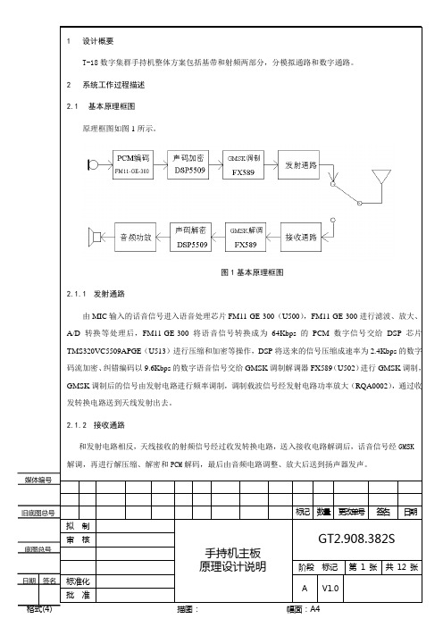
c)CPU复位由LTC3455复位电路提供的复位信号CPUREST完成
d)整机电源开关由LTC3455开关机电路提供。整机的充电、电量检测、电源的维持等均由LTC3455和MCU通信完成。LTC3455负载电流不超过500mA。
3.1.7.3
DSP使用TMS320VC5509,外挂4Mbit Flash(AD45D041),其主要工作:
c)在模拟接收状态下,由射频解调下来的语音信号将进入AK2368进行放大、滤波等优化处理语音信号后,通过音频放大驱动扬声器。
d)AK2368将负责MSK信号的收发。MSK信号由射频接收机解调到AK2368,再由AK2368经过相关处理后反馈到MCU,AK2368每收到8bytes的MSK信号就会向MCU发送一个脉冲告知MCU,然后由MCU进行分析。MCU通过AK2368产生的MSK信号并通过模拟通道发送出去。手持机和基站通过MSK信号完成入网等通信功能。
a)管理除GMSK调制解调器(CMX589)、PCM编解码器(FM11-GE-300)以外的其他设备包括射频电路、电源管理芯片LTC3455、LCD、键盘、音频功放LM4871、LM48511、振动电机、背光LED和收发LED等。
FS789 一维影像手持终端开发手册说明书

FS789一维影像手持终端开发手册FS789 Barcode Scan Mobile Terminal Development Manual Android 4.0 专为无线移动查询、采购、补货、收货、批发、盘点设计硬件参数联想A789设备参数手机类型:3G手机,智能手机主屏尺寸:4英寸触摸屏:电容屏,多点触控主屏材质:TFT主屏分辨率:800x480像素主屏色彩:1600万色网络类型:双卡双模网络模式:GSM,WCDMA数据业务:GPRS,EDGE,HSDPA支持频段:2G:GSM 850/900/1800/1900 3G:WCDMA 900/2100MHz操作系统:Android OS 4.0核心数:双核CPU型号:联发科MT6577CPU频率:1024MHzGPU型号:Imagination PowerVR SGX531 RAM容量:512MBROM容量:4GB存储卡:MicroSD卡,支持App2SD功能扩展容量:32GB电池容量:2000mAh键盘类型:虚拟键盘机身颜色:黑色联想A789数据功能WLAN功能:WIFI数据接口:Micro USB v2.0耳机插孔:3.5mm蓝牙传输WAP浏览器WWW浏览器联想A789商务功能办公工具:TXT,Quick Office,Adobe PDF,电子邮件飞行模式世界时间联想A789基本功能输入法:手写,笔画,拼音输入法输入方式:手写通话记录:已接+已拨+未接电话通讯录:名片式存储短信(SMS) 彩信(MMS) 免提通话录音功能情景模式待机图片主题菜单来电铃声识别来电图片识别日历功能闹钟功能计算器条码扫描参数每秒扫描次数:200次/秒解析精度:标准4Mil条码(0.1mm)读取范围:35mm至300mm读取方式:一维红光影像联想A789产品特性GPS导航:内置GPS,支持A-GPS重力感应器光线传感器距离传感器联想A789拍照功能摄像头:内置摄像头类型:双摄像头(前后)摄像头像素:前30万像素,后500万像素传感器类型:CMOS自动对焦:支持图像尺寸:最大支持2592×1944视频拍摄:支持联想A789娱乐功能视频播放:支持3GP/MP4等格式音频播放:支持MIDI/MP3/AAC等格式铃音描述:和弦,支持MP3/MIDI等格式开发语言EclipseJava条码读取原理FS789采用蓝牙传输方式将条码发送至手机,用户开发程序主要是蓝牙编程。
无线数据收集系统手持终端设计说明书

A Design of Digital Handheld Terminal in WirelessData Acquisition SystemXingguo SUNKey Lab of Intelligent Computing and Signal Processing of Ministry of Education, Anhui UniversityHefei, ChinaShouxian WENKey Lab of Intelligent Computing and Signal Processing of Ministry of Education, Anhui UniversityHefei, ChinaLei XUKey Lab of Intelligent Computing and Signal Processing of Ministry of Education, Anhui UniversityHefei, ChinaXiaohui LI*Key Lab of Intelligent Computing and Signal Processing of Ministry of Education, Anhui UniversityHefei, ChinaAbstract—In order to make data collection more convenient, quick and accurate in working site in the existing wireless data acquisition system, one kind of multi-function handheld terminal is designed which combines the wireless and wired data acquisition. The paper adopts Atmega128 of ATMEL as micro-controller, nRF905 of Nordic as data transmission module. It designs power management, liquid-crystal display and data storage circuits. The results of practical test show that the handheld terminal can be applied to all kinds of wireless data acquisition networks, and it has several advantages like easy to carry, large data storage capacity, rich function and low cost.Keywords-DS18B20 ; NRF905 ; Handheld terminal ; Data acquisition systemI.INTRODUCTIONWith the popularization of the large amount, cheap and highly integrated wireless module and the rapid development of wireless communication technology, the wireless data acquisition system has been widely used in industry, agriculture, medical and other fields. The existing wireless data acquisition system is composed of a convergent node, basic nodes and the server. The convergent node exchanges information with basic nodes by the radio frequency (RF) module or Zigbee module[1-4].Basic nodes collect information by the digital sensors and send it to the converge node in the form of packet. The data which is gathered by the converge node can be sent to the local server[5]or be transmitted to the remote server by GPRS [6]or GSM[7]. This way need to pay for the expensive network cost, and can not collect data conveniently, quickly and accurately[2].Based on the analysis above, this paper proposes a design scheme of handheld terminal. nRF905 is chosen as communication module which can realize remote transmission. We design the routing protocol which realizes automatic searching and manual setting. It makes the handheld terminal collect data information reliably in any effective area of the wireless network coverage and then display the data on LCD. Handheld terminal has the USB interface circuit which can be directly connected to the computer and allow computer to receive or send commands and data. In addition, it also supports the wired data acquisition, data printing.II.APPLICATIONSCENARIOFigure 1. Network StructureFigure 1 illustrates the network structure of application scenario. The wireless data acquisition system can be divided into three parts: extension, handheld terminal and the server.24LC256I/O1I/O2. . . . . .. . . . . .DS18B20. . . . . .. . . . . .. . . . . .. . . . . .DS18B20. . . .. . . .. . . .Figure 2. Extension Structure*Corresponding author.National Conference on Information Technology and Computer Science (CITCS 2012)Extension structure is shown in Figure 2. According to the received instructions, the extension samples the data of temperature and humidity and then transmits to the handheld. We use DS18B20 and SHT75 as temperature and humidity sensors respectively. The circuit of temperature data sampling adopts 1-Wire single-bus mode, so multiple temperature sensors can be mounted on each I/O port. In order to identify the physical location of DS18B20 and to facilitate the server data management, the corresponding layer information is written into the DS18B20 alarm trigger register[8]. When it’s power on, the extension reads DS18B20 ROM serial number and the layer information in alarm trigger register and then store ROM serial number in 24LC256 according to the different I/O ports and layer information. The physical location of DS18B20 can be determined according to the ROM serial number’s store address to realize the effective data management.Handheld terminal works as a convergent node in the wireless network .It collects the data of extension through the nRF905 and transmits it to the computer through the USB interface. In the working site, handheld terminal can search extension through the routing discovery menu and establish a routing table. According to the actual situation, we input an extension’s address. The handheld terminal will set up a path according to the routing table information to realize communication with the extension. The data will be displayed on the LCD after processed. Handheld terminal has data storage, data printing and cable numbering functions. Cable numbering can facilitate system maintenance. When an I/O port of a certain extension appears bad points, these points will be identified through measuring temperature. Handheld terminal ignores these bad points and rewrites layer information of other sensors through cable numbering function. In addition, handheld terminal can collect temperature and humidity data using wired way through link it to cable together directly in the following two cases. One case is that some small temperature and humidity acquisition systems will not use wireless extensions in order to reduce the cost; the other case is that the geographical position is too scattered to suitable for networking.The server transmits specified instructions to handheld terminal through the USB interface. The handheld terminal sends these instructions to the corresponding extension node through the wireless network. With this, the data can be gathered and passed back to the server. The server completes data analysis and management.III. D ESIGN OF HARDWARE CIRCUITHardware of handheld terminal consists of several parts,which is shown in Fig. 3.Figure 3. Hardware StructureA. Control ModuleThis paper chooses a low power consumption, high performance microprocessor Atmega128 as main control chip, which makes the handheld terminal processing faster and working longer. This module is a core control unit of handheld terminal. It obtains instructions from the keyboard and coordinates the whole system.B. Wireless ModuleThe wireless transceiver module adopts radio transceiver single-chip nRF905 which works in the 433/868/915MHz of ISM (Industrial Scientific Medical). The ShockBurst TM feature automatically handles preamble and the CRC (Cyclical Redundancy Check)[9]. In addition, the nRF905 has stand by and power down modes which can save more energy. The Atmega128 connects with nRF905 through SPI. When transmitting the data, the Atmega128 just sends the configuration register information, the receiver address and the transmitted data to nRF905, then nRF905 packages and sends all data (plus preamble and the CRC). When receiving the data, nRF905 detects the carrier and matches the address automatically. The data is received correctly and the preamble, address and CRC are removed, and then the data is transmitted to Atmega128 through SPI.C. Power ModuleLithium Battery is for power supply of the handheld. The charge management chip is CN3052. In the processing of charging, the system automatically switches to an external power to ensure that the system can still work. Once the charge cycle has terminated, the charging indicator light on the handheld will turn off. Due to the working voltage of printer module is 5V, while the other modules operating voltage is 3.3V. The proposed scheme chooses ME6211A33 as 3.3V voltage regulator and LTC1700 as 5V high-current output voltage regulator.D. Function ModuleThe handheld terminal uses CP2102 to achieve a high-speed interface to realize communication between the computer and the single-chip Atmega128. We use a 128×128 lattice LCD screen as display module and use 2×2 matrixkeyboard to realize man-machine information exchange. EN25B16 is a 2M bytes external storage flash and the data can be stored in it. The DS1302 will support time information. In addition, a printer module RD-OEM57V1 is embedded in the handheld terminal which supports data printing.IV. S OFTWARE D ESIGNThe embedded software of handheld terminal is programmed by C Language with the development of IAR Embedded Workbench, and adopts module program structure design. The main tasks of software include data processing, ask sequencing and job scheduling. When the program stars, handheld will initialize the system, including LCD, nRF905, the detecting of battery energy and the corresponding registers, then enter into the initial interface. User can select menu to complete the corresponding function by keyboard. Work flowdiagram of handheld is shown in Figure. 4Figure 4. The flow chart of the softwareThe communication protocol of the system bases on the master-slave structure. The extension can not initiatively launch communication, and it only has a passive response ability. In the system, each extension has two addresses: one is physical address; the other is network address. The physical address of all the extensions is 0xFF, but the network address is unique. When the extension receives instruction, it will determine whether the address correctly or not. Only the address is correct, the extension will execute instructions and return the data. Data frames format of nRF905 is as following table .ⅠTABLE I.D ATA F RAMEF ORMATType Route Route_Depth Route_ Direction DataType code is 1 byte, it is used to distinguish the different operations. Route is 5 bytes. It represents routing information which is obtained from the routing table. The first byte is the source address, the next byte is the destination address, the last 3 bytes are the relay address; the Route_Depth and Route_Direction are all 1 byte which are used to point to the next address. Data represents the transmitted data. If the data is less than 10 bytes, the remaining bits are complemented with 0. When the handheld failed to send message for 10 consecutive times, we can manually change the routing or alternatively enter the routing discovery phase. The wireless network uses dynamic routing mechanism[10]. Each frame of data contains the routing information from the source address to the destination address. The extension need not do any routing operations. It only transmits the data to the next extension, according to the routing information in the packet. During the routing discovery, the handheld terminal broadcasts RREQ packet to all extensions. If the received RREQ extension address is the destination address of routing requesting, the extension will return RREP packet to the handheld terminal, or it will forward RREQ packet. The RREP packet carries the routing information from the source address to the destination address. The flow diagram of route is shownin Figure 5.Figure 5.The flow diagram of routeV. T HE E XPERIMENTAL R ESULTSHandheld terminal collects temperature and humidity information of sensors which are mounted on NO.3 extension through NO.2 relay extension. NO.3 extension hangs two cables. There are six DS18B20 on each cable. The data results are shown in Figure 6.Figure 6. Experimental resultsVI.CONCLUSIONThis handheld terminal combines the wireless and wired data acquisition. It can detect data of working site by wireless way and collect temperature and humidity information by linking to cable directly. The handheld terminals can still work normally in the environment where working site has various forms or extension structure is complicate. In addition, handheld terminal can also connect with computer and allow PC to realize real-time detection, data backup, data sharing and so on.ACKNOWLEDGEMENTThis project is supported by the National Natural Science Foundation of China (No. 60972040), the Anhui Provincial Natural Science Foundation (No. 11040606Q06), the Provincial Project of Natural Science Research for Colleges and Universities of Anhui Province of China (No. KJ2012A003) and the 211 Project of Anhui University.REFERENCE[1]Chang Chun-bo. Design and Realization of the Wireless GrainInformation Monitoring Syestem of Low Power Consumption[D].Taiyuan: Taiyuan University of Technology, 2007 [2]Wang Quan, Chen Jia-lin, Xie Ying, Dai Jian-bo, Liu Chao. “Designand Implementation of Industrial Field ZigBee handheld Controller”, Journal of Microcomputer Information, Vol.25,No.5-2,2009[3]Wang Quan,Wang Jing-chuan,Wei Min,Chen Jia-lin. “Design andImplementation of Industrial Wireless Handheld Operator”,Journal of Industrial Control Computer, Vol.22,No.6,2009[4]Zheng Li-hua,Ling Qing-nian,Li Lu-wei. “The Design of Handset Basedon Industrial Wireless Network”,Journal of Electrical Measurement & Instrumentation,Vol.47,NO.536A, 2010[5]Jiang Xiao, Bei Jiang, Kan Jiang-ming, “Design of Wirelss Temperatureand Humidity Monitoring System of the Intelligent Greenhouse,”ICCET.Beijing, pp. 59-63 V3.April 2010[6]Rui Zhao, Kaixue Yao, Meng Wei. “The Research and Design ofEngine Room Temperature and Humidity Remote Monitoring System Based on GPRS,”IHMSC.Guiyang.pp.219-222. August 2011[7]Jifeng Ding, Jiyin Zhao, Biao Ma. “Remote monitoring system oftemperature and humidity based on GSM,”CISP.Dalian, pp.1-4. October 2009[8] Xu lei, Zhang Hong-wei, Li Xiao-hui and Wu Xian-liang. “A Design ofWireless Temperature and Humidity Monitoring System,”ICCT. Hefei, pp. 13-16. November 2010[9]Yingli Zhu, Wanghui Zeng and Lingqing Xie. “Design of MonitoringSystem for Coal Mine Safty Based on MSP430 and nRF905,”ISIE.Nanchang, pp. 98-101.October 2011[10]Dou Niu, Yan Zhang, Yanjuan Zhao, Mei Yang, “Research on RoutingProtocols in Ad Hoc Networks,” WNIS. Jilin, pp.27-30. October 2009。
实用的PDA设计方案样本

嵌入式系统智能手机(PDA)设计方案一、前言随着手持通信设备市场迅速发展, 手机功能逐渐增多。
当前手机已经不只是用于语音通信手持设备, 而成为集成了短信、彩信、上网以及移动办公等附加功能嵌入式通信平台。
集成了这些功能手机被称为智能手机。
近年, 嵌入式解决器运营速度和功能均有了很大提高, 使得许多此前只能在PC上实现应用, 当前都可以在手持设备上实现。
当前, 市面上智能手机重要采用Microsoft公司Pocket PC、Palm OS等商用操作系统, 但这些操作系统开放程序不够高, 限制了许多第三方应用软件移植。
为使智能手机可觉得第三方应用软件提供一种更为开放嵌入式平台, 本人对智能手机系统做了比较进一步研究, 提出一种以Linux作为嵌入式操作系统、MotorolaMX1作为微解决器、以WavecomQ2403A作为射频模块智能手机系统设计与实现。
二、智能手机(PDA)简介PDA是Personal Digital Assistant缩写, 字面意思是“个人数字助理”。
这种手持设备集中了计算, 电话, 传真, 和网络等各种功能。
它不但可用来管理个人信息(如通讯录, 筹划等), 更重要是可以上网浏览, 收发Email, 可以发传真, 甚至还可以当作手机来用。
尤为重要是, 这些功能都可以通过无线方式实现。
固然, 并不是任何PDA都具备以上所有功能;虽然具备, 也也许由于缺少相应服务而不能实现。
但可以预见, PDA发展趋势和潮流就是计算、通信、网络、存储、娱乐、电子商务等多功能融合。
PDA普通都不配备键盘, 而用手写输入或语音输入。
PDA所使用操作系统重要有Palm OS, Windows CE和EPOC。
三、个人PDA需求分析作为3C融合到一种终端典范智能手机, 除了实现通讯功能外, 还可以实现诸多计算机和消费电子产品功能, 并且体积小, 具备便携性和多功能性双重优势, 通过安装应用软件后, 能随时随处满足不同消费者差别化需求, 因而具备其她产品不可代替独特优势。
基于Android平台的智能手持设备设计与开发

基于Android平台的智能手持设备设计与开发随着科技的不断发展,人们对于智能手持设备的需求越来越高。
作为现代社会的重要工具,智能手持设备在人们的日常生活中发挥着越来越重要的作用。
本文将重点介绍基于Android平台的智能手持设备的设计与开发。
一、需求分析在进行智能手持设备的设计与开发之前,我们需要首先对需求进行分析。
智能手持设备的主要功能涵盖了通信、计算、娱乐、生活等多个方面。
因此,在设计与开发的过程中,我们需要确保设备具备以下基本功能:1.通信功能:支持蓝牙、WiFi、4G网络等通信方式,以便用户能够进行网络通信、数据传输和获取信息等操作。
2.计算功能:要求设备具备高性能的处理器、足够的存储空间和内存,以确保设备能够运行各种应用程序并保持稳定性。
3.娱乐功能:需要支持多媒体功能,包括音乐播放、视频播放、游戏等,以满足用户的娱乐需求。
4.生活功能:要求设备具备日历、闹钟、天气预报等实用工具,方便用户进行日常生活管理。
5.安全功能:要求设备具备密码锁、数据加密等安全功能,以保护用户的隐私和数据安全。
二、设计与开发在进行设计与开发时,我们需要按照Android平台的开发规范进行操作。
以下是设计与开发过程的基本步骤:1.确定用户界面(UI)设计:在设计智能手持设备的界面时,我们需要参考Android的设计规范,确保用户界面简洁、易用、美观。
2.选择适合的开发工具:Android平台提供了多种开发工具,开发人员可以选择合适的开发工具来进行开发工作。
例如,Android Studio是一种非常流行的开发工具,可以提供丰富的开发功能。
3.编写代码:在进行Android应用程序的开发过程中,需要编写相应的代码。
根据需求进行功能模块的划分,分别编写模块的代码。
4.进行测试与调试:完成代码编写之后,我们需要进行测试和调试工作,以保证设备的稳定性和功能的正常运行。
5.发布与推广:在设备的设计与开发完成后,我们需要进行发布与推广工作,将设备推向市场,让更多的用户了解并使用该设备。
机械手毕业设计说明书

机械手毕业设计说明书一、设计目的本毕业设计旨在设计一种机械手,能够根据预先设定的程序自动执行各种操作。
通过该设计,可以提高工作效率,减少人力成本,同时具备高精度和高可靠性。
二、设计背景近年来,随着工业自动化的不断发展,机械手在工业生产中的应用越来越广泛。
机械手凭借其高速、高精度、高可靠性等优势,成为工厂生产线上的重要设备之一。
因此,设计一种功能强大的机械手对于工业生产的提升具有重要意义。
三、设计内容1.机械结构设计本设计采用七自由度机械手结构,包括基座、旋转关节、摇摆关节、剪切关节以及爪子等部分。
结构设计中要考虑刚性、稳定性以及重量平衡等因素,确保机械手能够准确地执行各种操作。
2.传感器系统设计为了使机械手具备自主感知能力,本设计将配备多种传感器,如力传感器、视觉传感器等。
通过传感器系统的设计,机械手可以根据实时的反馈信息进行运动控制,提高操作的准确性和安全性。
3.运动控制系统设计运动控制系统是机械手的核心部分,本设计将采用PLC (可编程逻辑控制器)作为控制器,结合伺服驱动器实现机械手的精确定位和协调运动。
通过编写程序,机械手可以根据预先设定的路径和信号执行各种操作。
四、设计过程1.需求分析针对机械手的应用场景和功能需求,进行需求分析。
确定机械手所需执行的任务类型、速度要求、负载能力等。
2.机械结构设计根据需求分析,设计机械手的结构,包括基座、旋转关节、摇摆关节、剪切关节和爪子等。
进行力学分析和模拟,确保结构设计的合理性和可靠性。
3.传感器系统设计根据需求分析,确定机械手所需的传感器类型和数量。
选择合适的传感器并安装在机械手上,设计传感器的接口电路和数据处理算法。
4.运动控制系统设计选择合适的PLC和伺服驱动器,进行硬件选型和连接。
编写控制程序,实现机械手的位置控制、速度控制和力控制等功能。
5.整体集成与测试将机械结构、传感器系统和运动控制系统进行整体集成。
进行系统测试,检验机械手的功能和性能是否满足设计要求。
手持机移动端概要设计说明书V
手持机移动端概要设计说明书北京盛威时代信息科技有限公司北京盛威时代信息科技有限公司对本文件资料享受著作权及其它专属权利,未经书面许可,不得将该等文件资料(其全部或任何部分)披露予任何第三方,或进行修改后使用。
文件更改摘要:目录文件更改摘要:..........................................错误!未指定书签。
. 引言......................................................... 错误!未指定书签。
目的 ..........................................................错误!未指定书签。
术语及缩略语..............................................错误!未指定书签。
参考资料....................................................错误!未指定书签。
. 概述......................................................... 错误!未指定书签。
背景 ..........................................................错误!未指定书签。
范围 ..........................................................错误!未指定书签。
目标 ..........................................................错误!未指定书签。
设计约束、限制...........................................错误!未指定书签。
. 总体设计................................................... 错误!未指定书签。
- 1、下载文档前请自行甄别文档内容的完整性,平台不提供额外的编辑、内容补充、找答案等附加服务。
- 2、"仅部分预览"的文档,不可在线预览部分如存在完整性等问题,可反馈申请退款(可完整预览的文档不适用该条件!)。
- 3、如文档侵犯您的权益,请联系客服反馈,我们会尽快为您处理(人工客服工作时间:9:00-18:30)。
手持机开发设计说明原来的手持机采用STC51单片机开发的,由于51单片机的种种局限,已经不能适应目前的环境了,想用STM32单片机,加TFT显示,USB接口,COMS摄像等功能。
基本功能如下:手持机功能说明* 刷卡计费功能,并记录消费。
* 查询消费记录。
* 通过232串口,可把消费记录上传到电脑。
* 除车位锁外,还可控制各种其他动作终端,使用灵活。
* 选用名牌微电脑控制芯片和电源控制芯片,工作性能稳定可靠,效率高,功耗低。
* 手持机全中文功能界面显示,操作简单。
* 进入车辆发卡,向卡内写入车辆进入管理区时间。
* 车辆离开刷卡,读取卡内的时间数据。
* 自动计算停车时间,将停车时间XX日XX时XX分显示在液晶屏。
* 自动计算停车应收费用金额。
* 随时可查阅停车收费总金额、进车次数等信息。
* 两级管理,管理级对员工级管理,员工级对进出车辆级管理。
* 填写收费规则,管理级可通过管理卡填写收费规则。
* 清除相关信息,管理级可通过管理卡对停车收费总金额、收费时间等信息一次性清除。
* 时间调整,管理级可通过管理卡进行时间校对。
* 识别和判断内部卡是否有效。
* 电量不足声响及显示提示。
* 随时可将停车收费总金额及收费笔数转存到财务卡内。
* 充电功能。
* 可无线控制:车位锁/道闸/显示屏等。
* 可将收费资料与车牌号码同时上传计算机。
一、手持机管理系统特点1、灵活性:可以在任何两个出入口或一个出入口实现整个停车交易流程。
2、便捷性:安装简易,无需大规模施工,机动性强,无需专用的PC机管理。
3、经济性:系统及设备价格对比同类产品优势明显,具有很高的性价比。
4、智能性:由于利用智能卡和计费机管理,原有的数据收集和整理工作更为简洁准确,避免票款的流失、所需统计数据的准确性大大提高。
5、多样性:手持机+道闸(车位锁)复合使用时,比较适用多车道进出口的管理,可实现进出车辆的分流。
6、服务性:停车管理的反复读写性,可以简化了临时停车证的制作及用户更换带来的麻烦。
二、 手持机操作说明1. 开机按住ON(返回键),待液晶屏上显示如图1所示内容时松开即可。
图1驿龙科技车辆管理系统00:00 00年00月00日通信指示灯(灯闪烁表示通讯中)欠压指示灯(灯亮表示欠压,应立即充电) 电源指示灯(灯亮表示电源正常)关机键、操作过程中确认键出车键(功能详见文字说明)关闭道闸(或车位锁)键(功能详见文字说明)开机键、操作过程中的返回键操作中左移键或主菜单中下班刷卡键进车键(功能详见文字说明)打开道闸(或车位锁)键(功能详见文字说明)操作中右移键或主菜单中上班刷卡键 数字键主菜单键(功能详见文字说明)显示窗口2. 关机按OFF(确认键)即可。
3. 进入功能菜单按菜单键即可3.1菜单功能说明按“菜单”键进入主菜单,通过上移键或下移键选择某一功能,通过确认键及返回键进行具体操作。
本系统设置如下12个主菜单; 1-------查询收费金额 2-------查询进出车辆 3-------下载停车资料 4-------用财务卡取款 5-------查财务卡金额 6-------清财务卡金额 7-------相关资料清空 8-------校正系统时间 9-------重要参数设置 10------请注册管理卡 11------考勤资料查询 12------输入系统密令3.2主要菜单功能的操作说明3.2.1查询收费金额通过上移键或下移键选择“查询收费金额”功能,按下确认键,液晶屏上显示图2等待几秒后自动退回主菜单。
3.2.2查询进出车辆按确认键显示图3收费数目:0000 信息数目:0000 金额数目:0000 查询进出车辆01进车查询 02出车查询03进出车数目查询图3查询进车车辆:按1键显示图4。
图4按1键:按后面(4.1节)介绍的输入车牌号方法输入要查询的车牌号类似图6,确认后再按确认键;如果该车已经登记,则显示类似图7的信息;若该车未登记,则显示“未登记记录”,等待几秒后自动退回主菜单。
按2键:从第一个进入管理区的车辆登记开始显示,可通过“↓”键查看下一个进入车辆登记,通过“↑” 键查看上一个进入车辆登记直到显示“查询完毕”,自动退回主菜单。
在整个查询过程中随时可能通过“返回”键,返回上一级菜单。
查询出车车辆:按2键显示类似图4。
按1键:按后面(4.1节)介绍的输入车牌号方法输入要查询的车牌号类似图6,若确认后再按确认键;如果该车已经登记,则显示类似图10的信息;若该车未登记,则显示“未登记记录”,自动退回主菜单。
按2键:从第一个进行管理区的车辆登记开始显示,通过 “↓” 键查看下一个进入车辆登记,通过“↑” 键查看上一个进入车辆登记直到显示“查询完毕”,自动退回主菜单。
在整个查询过程中随时可能通过“返回”键,返回上一级菜单。
3.2.3进出车数目查询按确认键,如下显示:进车数目为该手持机所刷的进车卡数目,出车数目为该手持机所刷的出车卡数目。
3.2.4下载停车资料(配合车场管理软件和PC 机)3.2.3.1 将通讯装置一端与手持机通讯端口相连接,另一端与计算机通讯口相连接,连接无误后进行下一步操作;3.2.3.2 选择下载停车资料功能后按确认键即可进行与计算机通讯操作,这时手持机显示“下载停车资料”3.2.3.3 计算机部分操作见软件包里的“帮助”栏目; 3.2.3.4 若要停止此功能操作按返回键或关机键即可。
3.2.5用财务卡取款选择此功能后显示图:01车牌查询 02逐一查询用财务卡取款 请刷卡进车数目:×××× 出车数目:××××按正确方法刷财务卡后显示3.2.6查财务金额选择此功能后显示:按正确方法刷财务卡后显示卡内的金额:注释:只允许持有管理卡者或知道密码者方可操作此功能。
3.2.7清财务卡金额注释:只允许持有管理卡者或知道密码者方可操作此功能。
3.2.6.1 选择此功能后显示屏提示输入密码或刷管理卡。
3.2.6.2 输入密码通过或刷管理卡通过后显示:3.2.6.3 扫正确方法刷财务卡后显示:3.2.8相关资料清空注释:只允许持有管理卡者或知道密码者可操作此功能。
3.2.7.1 选择此功能后显示屏提示输入密码或刷管理卡。
3.2.7.2 输入密码通过或刷管理卡通过后显示图;3.2.7.3 按确认键则删除资料。
删除后蜂鸣器会提示响一声。
返回键则退出操作3.2.9校正系统时间注释:只允许持有管理卡可知道密码者方可操作此功能。
3.2.8.1 选择此功能后显示屏提示输入密码或刷管理卡。
3.2.8.2 输入密码通过或刷管理卡通过后显示:操作成功查财务金额 请刷卡 清财务卡金额请刷卡 操作成功资料删除!00:0000年00月00年00日00003.2.8.3 通过“↓”键移动决定“年”“月”“日”“时”“分”的位置,通过数字键在闪烁的位置处填写时钟数字;3.2.8.4 调整完毕并确认正确后按确认键即可。
3.2.10换岗说明3.2.9.1上班卡:按 “→”键液晶屏有相应的刷卡提示信息,系统记录下该卡的上班的信息 为便于计算机操作,财务卡也当作换岗或交班的依据。
3.2.9.2上一班工作人员用财务卡取款:取款操作参见3.2.4,用财务卡取款一节3.2.9.3下班卡:按“←”键液晶屏有相应的刷卡提示信息,系统记录下该卡的下班的信息3.2.11重要参数设置进入菜单,如下显示:输入密码,正确则进行下一步操作,若不正确重新输入密码。
按返回键则返回上一菜单,该菜单下主要是收费规定,可根据客户要求更改,具体操作略。
3.2.12请注册管理卡进入菜单,如下显示:输入密码正确则进行下一步操作,否则重新输入正确密码。
按返回键,则返回上一级菜单输入卡所对应的车位的号码,按确认键进行下一步操作,按返回键返回。
按数字1键,则进行临时卡的注册,如下提示,把未注册卡放入刷卡区若刷卡成功,则蜂鸣器会发出“嘀”的一声,不成功则会有如下提示:按数字2键,则进行年卡的注册;数字3键则进行财务卡的注册……请输入密码 请输入密码 请输入车位号: 0000 01临时卡 05管理卡 02年卡 03财务卡 04考勤卡 请刷卡: 刷卡错误3.2.12考勤资料的查询按确认键,进入该菜单操作:输入正确密码,则显示A 为上班时间,B 为下班时间,金额为该卡在该时间段所收的费用,按“↓”键则可以进行下一班的查询,按“↑”键则可以进行上一班的查询。
3.2.13输入系统密令按确认键进入该菜单操作输入正确密码,则如下显示,返回键则返回上一级菜单按数字1键,则会使数据存储重新从初始地址开始处存储; 按数字2键,则会使手持机内收费金额总数清零; 按数字3键,则重新修改密码;按数字4键,则会使手持机内进出车记录总数清零; 按数字5键,则会使手持机内收费总次数清零。
4. 操作流程 4.1进入车辆发卡4.1.1按进车键:液晶屏提示输入车类型,车牌号,使用者通过反复触按下移键选择车牌汉字、车牌字母及车牌数字。
车辆进入请选择 (01)大车 (02)小车请输入密码 考勤卡号×××××× A ××月××时××分 B ××月××时××分 金额 0000元 请输入密码 01清00 05清收费 02清金额 03重设置密码 04清进车记录图54.1.2按1或2键选择车的类型。
图6若选择车牌汉字或车牌字母时液晶屏下方有相应代码,使用者按键入“←” 或“ →”键,液晶屏下方的汉字或字母会不断变化,若有你所选的车牌汉字或车牌字母,然后再键入该汉字或字母的行标数字即确定所选择的汉字或字母。
例如黑字,按2键即可,上排的车牌号会显示黑字。
按键“↓”和“↑”可以移动输入车牌号前后的位置,若不想输入车牌,进入图6后按确认键即可。
图74.1.3按确认键进行以下操作,按返回键则退出。
图8如果没卡或读卡错误系统会提示读卡错误,若卡的类型不对系统会提示该卡为什么类型,“此卡为管理卡”“此卡为出车卡”“此卡为财务卡”“未注册卡”等显示。
如果刷卡正确,蜂鸣器发出嘀的提示声,同时通信指示灯亮,手持机会把读到卡所对应的车位锁地址,通过无线发送,关闭所对应的车位锁(通常锁是打开的,车辆进入后刷卡就关闭,开始计费)。
如果需连续刷进车卡重复按动进车键即可。
4.2车辆离开结算4.2.1按出车键:图94.2.2刷卡:从车辆使用者手中收回出车卡,并按正确刷卡方法刷卡,待液晶屏上显示如图10所示内容时进行下一步操作,若刷卡时,液晶并出现:“此卡为管理卡”“此卡为出车卡”“此卡为财务卡”“未注册卡”等显示时,应及时更换为出车卡操作。