Telink 产品简介
国产手机MTK平台发展及芯片功能介绍
联发科MTK平台发展,各芯片功能介绍及MTK工程模式祥表时间:2009-03-21 23:52:51 来源:作者:MTK芯片是全球排名前十名的专业IC设计公司——台湾联发科技公司生产。
它的主要特点:一是低成本,对于竟争激烈的手机市场是最好的选择;二是芯片具有音乐和视频功能,满足了MP3和MP4的需求;三是芯片集成度高,功能较多技术性能好,迎合了市场的需要。
MTK平台发展及各芯片功能介绍1、MT6205、MT6217、MT6218、MT6219、MT6226、MT6227、MT6228均为基带芯片,所以芯片均采用ARM7的核;2、MT6305、MT6305B为电源管理芯片;3、MT6129为射频芯片,转换射频信号;RF3146(7×7mm)、RF3146D(双频)、RF3166(6×6mm)为RFMD(美国RF微器件公司在有设五个设计中心,专用射频集成电路(RFIC)供应商RF Micro Devices, Inc. 公司(Nasdaq 股市代号:RFMD))的功放;MT6205为最早的方案,只有GSM的基本功能,不支持GPRS、WAP、MP3等功能。
MT6218为在MT6205基础上增加GPRS、WAP、MP3功能(MT6217为MT6218的cost down方案,与MT6128 PIN TO PIN(就是说每个pin脚定义都是与AKM和TI芯片一样的,能够贴AKM或TI 芯片的PCB上,不做任何改动就可贴他们的芯片),只是软件不同而已,另外MT6217支持16bit数据。
MT6219为MT6218上增加内置AIT的1.3M camera(照相摄像)处理IC,增加MP4功能。
8bit数据。
MT6226为MT6219 cost down(降低成本)产品,内置30万camera(摄相头)处理IC,支持GPRS、WAP、MP3、MP4等,内部配置比MT6219优化及改善,比如配蓝牙是可用很便宜的芯片CSR的BC03模块USD3即可支持数据传输(如听立体声MP3等)功能。
华为SmartLi系列产品介绍说明书
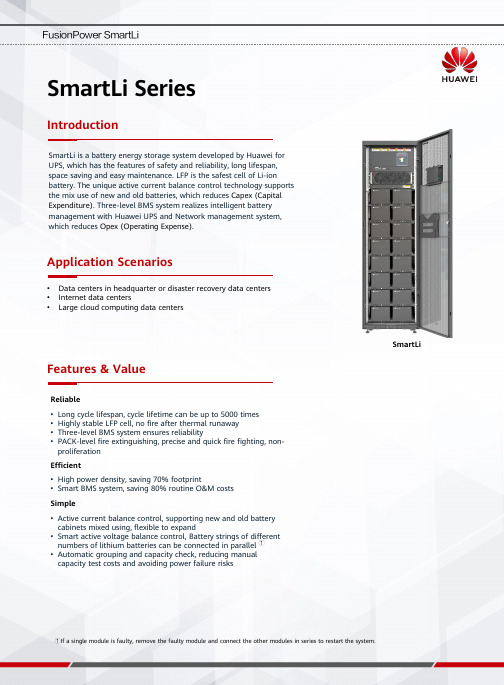
SmartLi SeriesIntroductionFeatures & ValueSmartLiSmartLi is a battery energy storage system developed by Huawei for UPS, which has the features of safety and reliability, long lifespan, space saving and easy maintenance. LFP is the safest cell of Li-ionbattery. The unique active current balance control technology supports the mix use of new and old batteries, which reduces Capex (Capital Expenditure). Three-level BMS system realizes intelligent battery management with Huawei UPS and Network management system, which reduces Opex (Operating Expense).Reliable •Long cycle lifespan, cycle lifetime can be up to 5000times •Highly stable LFP cell, no fire after thermal runaway •Three-level BMS system ensures reliability•PACK-level fire extinguishing, precise and quick fire fighting, non-proliferationEfficient•High power density, saving 70% footprint•Smart BMS system, saving 80% routine O&M costs Simple•Active current balance control, supporting new and old battery cabinets mixed using, flexible to expand•Smart active voltage balance control, Battery strings of different numbers of lithium batteries can be connected in parallel ①•Automatic grouping and capacity check, reducing manual capacity test costs and avoiding power failure risks①If a single module is faulty, remove the faulty module and connect the other modules in series to restart the system.•Data centers in headquarter or disaster recovery data centers •Internet data centers•Large cloud computing data centersApplication ScenariosBattery Module and Cabinet SpecificationsItemDescriptionBasic ParametersIP Protection Level IP21 according to IEC60529 standardMounting Type Against the wall.Reserve at least 800 mm from thefront.EMCSurge IEC61000-4-5ESDIEC61000-4-2Radiated electric fieldsIEC61000-4-3EmissionIEC62040-3EnvironmentStorage Temperature 0ºC -40ºC Transportation Temperature -40ºC to 60ºCOperating Temperature 0ºC -40ºC (20-25°C is recommended)Relative Humidity 5% -95%Max. Operating Altitude0 -4000m. Derating is required if the altitude exceeds1000 m*CellModule Full Cabinet Half Cabinet Configuration Single cell 20S3P 2 groups 1 group Nominal Capacity 27Ah 81Ah 162Ah 81Ah Capacity for calculating the backup time 25.5Ah 76.5Ah 153Ah 76.5Ah Nominal Voltage3.2Vdc64Vdc512Vdc(8+8)448Vdc(7+7)384Vdc(6+6)512Vdc(8+0)448Vdc(7+0)384Vdc(6+0)Charging Voltage 3.4Vdc 68Vdc 544Vdc(8+8)476Vdc(7+7)408Vdc(6+6)544Vdc(8+0)476Vdc(7+0)408Vdc(6+0)Dimension(W*D*H: mm)21*100*140210*765*160600*850*2000600*850*2000Weight605g50kg1000kg@7+7650kg@7+0System SpecificationsItemDescriptionBasic ParametersProduct Model SmartLi Battery Cell Material LiFePO4(6C)Charging Current ≤ 1C, 0.5C by default Cycle Life 5000 cycles @ 50% DODNominal Capacity 162Ah / 82.94kWh (8+8);162Ah / 72.57kWh (7+7);162Ah / 62.20kWh (6+6);Capacity for calculating the backup time ②153Ah / 78.33kWh (8+8);153Ah / 68.54kWh (7+7);153Ah / 58.75kWh (6+6);Weight1100kg (8+8);1000kg (7+7);900kg (6+6)Dimension (W*D*H)600mm*850mm*2000mm Self Discharge ≤5% (0-30℃/3 months)Fire protectionModule-levelCommunication Interface FE, RS485, Dry contactsProtection Over temperature, over current, short circuit, over charge/discharge, etc.Design Life 15 yearsCertification UL1642, UN38.3, IEC62619, IEC62040,RoHs Compatibility Huawei UPS, third-party UPS/HVDCDischarge capability 300 kW@10 minutes or 200 kW@15 minutes (7+7, 20-30°C)②The backup time is calculated based on the capacity 68.54 kWh and the capacity under different backup time or discharge rates.68.54kWh=25.5Ah*3*2*3.2V*20*7 (The battery cell is 27 Ah. The margin is calculated based on the reserved 25.5 Ah. For details, refer to the battery cell certification report.)Monitoring……NetEcoUPS…………Network managementThird-level SBCU systemIntelligent battery management module (Built-in second-levelBCU system)Intelligent battery management module (Built-in second-levelBCU system)Battery module (Built-in first-level BMU)Battery module (Built-in first-levelBMU)Battery module(Built-in first-level BMU)Battery module (Built-in first-levelBMU)Battery module (Built-in first-level BMU)Battery module(Built-in first-levelBMU)Battery module (Built-in first-level BMU)Battery module(Built-in first-levelBMU)MonitoringBMU BCU SBCU MonitoredObject Battery Pack Battery Rack SystemFunction Description •Measure the cell voltage,temperature.•Electrochemical cell voltageequalization;•Communicates with the BMS.•Save the battery modulefault information•Manages all BMUs•Collects statistics onthe battery voltage,temperature, SOC,and SOH, and reportsthe statistics to theSBCU.•Detects the chargeand dischargecurrents of batterystrings to adjust theparallel currentsharing.•Protects the hardwareand batteries againstexceptions,disconnects the loopin a timely mannerwhen an exceptionoccurs, and reportsthe exception to theSBCU.•Save the batterycabinet faultinformation.•Displays the total voltage,SOC, SOH, current, andtemperature of the batterysystem, and batteryinformation of each batterycabinet.•Receives commonparameters reported by eachBCU and saves local data.•Receives alarms andprotection events reported bythe BCU and saves the eventslocally.•Communicates with the UPS,provides human-machineinteraction, communicationsports, and permissionmanagement for local andremote operations, setsbattery management systemparameters, and upgradesprograms.Measurement Parameter Cell voltage Cabinet Voltage System Voltage Cell temperature Cabinet Current System CurrentMeasurement Precision 0.2% (voltage)2℃(temperature)1% (voltage)2% (>40A); 3A (<40A)1% (voltage)2% (>40A); 3A (<40A)Display information Battery Module Cell Voltage Battery Cabinet Voltage Battery System Voltage Battery Module SOH Battery Cabinet Current Battery System Current Battery Module SOC Battery Cabinet SOC Battery System SOCBattery Module Maximum CellVoltage Battery Cabinet SOH Battery System SOHBattery Module Minimum CellVoltageBattery CabinetMaximum Cell VoltageBattery System Maximum CellVoltageBattery Module Maximum CellTemperatureBattery CabinetMinimum Cell VoltageBattery System Minimum CellVoltageBattery Module Minimum CellTemperatureBattery CabinetMaximum CellTemperatureBattery System Maximum CellTemperatureBattery CabinetMinimum CellTemperatureBattery System Minimum CellTemperatureDischarge Times Battery CapacityDischarge Capacity Discharge TimesDischarge CapacityProtection FunctionAlarm Type Alarm Description Alarm CauseAlarm ConfirmationTimeSolutionBattery charge protection Low temperature protection underbattery chargeThe temperature of battery cell isunder -5℃.30s Alarm Over temperature protection underbattery chargeThe temperature of battery cellabove 67℃.30sTrip offbatterybreaker Over voltage protection of batterycellThe voltage of battery cell isabove 3.9V1sOver voltage protection of batterystring.The voltage of battery string isabove 3.625N V1sOver current protection of batterycharge>200A 20msBattery discharge protection Low temperature protection underbattery dischargeThe temperature of battery cell isunder -5℃30sTrip offbatterybreaker Over temperature protection underbattery dischargeThe temperature of battery cellabove 67℃30sLow voltage protection of batterycellThe voltage of battery cell isunder 2.3V700msLow voltage protection of batterystringThe voltage of battery string isunder 2.55N V2s AlarmOver current protection of batterydischarge>580A 30sTrip offbatterybreakerBattery charge alarm Low temperature alarm underbattery chargeThe temperature of battery cell isunder 5℃30sAlarm Over temperature alarm underbattery chargeThe temperature of battery cellabove 55℃30sOver voltage alarm of battery cell The voltage of battery cell isabove 3.8V5sOver voltage alarm of batterystring.The voltage of battery string isabove 3.55N V5sOver current alarm of batterycharge>96A 5sBattery discharge alarm Low temperature alarm underbattery dischargeThe temperature of battery cell isunder 5℃30sAlarm Over temperature alarm underbattery dischargeThe temperature of battery cellabove 60℃30sLow voltage alarm of battery cell The voltage of battery cell isunder 2.6V5sLow voltage alarm of batterystring.The voltage of battery string isunder 2.8N V5sOver current alarm of batterydischarge>500A 10sCharge at Different Charging TateDischarge at Different Discharge RateLifetime at Different TemperatureCycle Lifetime at Different Temperature and DODCopyright©Huawei Technologies Co.,Ltd.2021.All rights reserved.No part of this document may be reproduced or transmitted in any form or by any means without prior written consent of Huawei Technologies Co.,Ltd.。
中联泰楼宇对讲产品演示

系统具备报警功能,如遇异常情况( 如非法入侵、火灾等),系统会自动 报警并推送信息至物业管理人员。
03
CATALOGUE
安装与使用
安装步骤
准备工具与材料
确保准备齐全安装所需 的工具和材料,如螺丝 刀、绝缘胶带、线缆等
。
开箱检查
打开产品包装,检查楼 宇对讲系统的各个部件 是否齐全,有无损坏。
3
客户评价3
中联泰的服务态度很好,售后有保障,让人很满 意。
客户建议
客户建议1
希望中联泰能推出更多智能化功能,满足现代 家庭的需求。
客户建议2
希望产品的外观设计更加时尚,更符合现代家 居风格。
客户建议3
希望中联泰能提供更多样化的产品选择,满足不同客户的需求。
客户问题解答
客户问题1
问:如何设置楼宇对讲系统的呼叫 功能?
远程开门
物业管理人员可通过管理软件远程控制单元门的 开关,方便快捷。
物业管理功能
01
02
03
监控系统
集成监控系统,可实时查 看小区各个角落的监控画 面,保障小区安全。
报修管理
住户可通过系统提交报修 申请,物业管理人员在线 接收并处理,提高工作效 率。
费用收缴
支持在线缴纳物业费、停 车费等费用,方便快捷, 减少人工操作成本。
连接线路
根据产品附带的接线图 ,正确连接电源线、音
频线等明书的指示安装在 指定位置,并确保牢固
。
使用说明
01
用户注册
新用户需要按照系统提示完成注册 ,以便使用各项功能。
访客管理
住户可通过楼宇对讲系统查看访客 图像,控制楼门的开启。
03
02
通话操作
亿佰特-TLSR8359 2.4GHz低功耗纯硬件SoC无线模块 E03-2G4M10S使用手册

目录第一章概述 (1)1.1 简介 (1)1.2 特点功能 (1)1.3 应用场景 (1)第二章规格参数 (1)2.1 极限参数 (1)2.2 工作参数 (2)第三章机械尺寸与引脚定义 (3)第四章基本操作 (4)4.1 硬件设计 (4)第五章常见问题 (5)5.1 传输距离不理想 (5)5.2 模块易损坏 (5)5.3 误码率太高 (5)第六章焊接作业指导 (6)6.1 回流焊温度 (6)6.2 回流焊曲线图 (6)第七章天线指南 (7)7.1 天线推荐 (7)第八章批量包装方式 (7)第一章概述1.1 简介E03-2G4M10S是基于TELINK TLSR8359无线SOC设计生产的一款小体积、低功耗、高可靠性、工作在2.4GHz 频段的模块,芯片自带32位高性能MCU,发射功率最高可达到10dBm。
TLSR8359支持硬件OTA升级和多种启动切换,方便产品的特性推出和升级,由于该模块是纯硬件类SoC模块,需要用户对其编程后方可使用。
1.2 特点功能●最大发射功率10dBm,软件多级可调;●支持全球免许可ISM 2.4GHz频段;●14位ADC与PGA,● 6通道PWM●一个正交解码器(QDEC),●丰富和灵活的GPIO接口;●丰富的资源,512kB FLASH,64kB RAM;●支持1.8~3.6V供电,大于3.3V供电均可保证最佳性能;●工业级标准设计,支持-40~+85℃下使用;●理想条件下,通信距离可达600m;1.3 应用场景●零售/物流●专用网络●灯塔第二章规格参数2.1 极限参数2.2 工作参数第三章机械尺寸与引脚定义第四章基本操作4.1硬件设计●推荐使用直流稳压电源对该模块进行供电,电源纹波系数尽量小,模块需可靠接地;●请注意电源正负极的正确连接,如反接可能会导致模块永久性损坏;●请检查供电电源,确保在推荐供电电压之间,如超过最大值会造成模块永久性损坏;●请检查电源稳定性,电压不能大幅频繁波动;●在针对模块设计供电电路时,往往推荐保留30%以上余量,有整机利于长期稳定地工作;●模块应尽量远离电源、变压器、高频走线等电磁干扰较大的部分;●高频数字走线、高频模拟走线、电源走线必须避开模块下方,若实在需要经过模块下方,假设模块焊接在Top Layer,在模块接触部分的Top Layer铺地铜(全部铺铜并良好接地),必须靠近模块数字部分并走线在Bottom Layer;●假设模块焊接或放置在Top Layer,在Bottom Layer或者其他层随意走线也是错误的,会在不同程度影响模块的杂散以及接收灵敏度;●假设模块周围有存在较大电磁干扰的器件也会极大影响模块的性能,跟据干扰的强度建议适当远离模块,若情况允许可以做适当的隔离与屏蔽;●假设模块周围有存在较大电磁干扰的走线(高频数字、高频模拟、电源走线)也会极大影响模块的性能,跟据干扰的强度建议适当远离模块,若情况允许可以做适当的隔离与屏蔽;●通信线若使用5V电平,必须串联1k-5.1k电阻(不推荐,仍有损坏风险);●尽量远离部分物理层亦为2.4GHz的TTL协议,例如:USB3.0;●天线安装结构对模块性能有较大影响,务必保证天线外露,最好垂直向上。
LEADTECK领泰产品方案应用

11.3 16.4
6.8 10.8
7.5 10.7
5.1 6.6
5.4 7.3
9.1 16.8
8.5
13
49
64
37
52
27
35
9.6 12.4
18
26
LT4805SQ P+P
SOP-8L
-30 ±20 18
21
LT9926SQ-X N+N
SOP-8L
20 ±12
24.4 29.4
LT9926SQ N+N
LT7446FL
N
PDFN3X3-8L
30 ±20
LT7446FN N TDFN3.3X3.3-8L 30 ±20
LT7468FL
N
LT7468FL-Y N
LT4953SQ P+P
LT4807SQ P+P
LT4803SQ LT3810FR
P+P
N+N 串联
LT4805SQ-X P+P
PDFN3X3-8L PDFN3X3-8L
SOP-8L
20 ±12
19
26
LT3810FP
N+N 并联
PDFN3X3-8L
30 ±20 12
19
同向
MOSFET在交换机上应用
Part Number TYP
LT0110SR N
LT0115SR N
LTS0150SQ N
LT1528SJ
P
LT1520SJ
P
Package
TO252-2L TO252-2L SOP-8L SOT23-3L SOT23-3L
LT4812SQ-Y N+N
意力速公司介绍

主打产品・Core Business
连接器(Connector)・・・・・・・・・・・・・・・・・・・・・・・・・・・ 90%
基板对基板连接器(Board to Board Connector)・・・・・・・・・・ 33%
FPC/FFC连接器(FPC/FFC Type Connector)・・・・・・・・・・ 30%
针对客户服务的特长
世界范围营业活动的推进 (日・美・欧・亚)
直接销售体制的彻底完善 ①全球范围的服务 ②最合适地的交易服务
应用合理化建议 评价・分析的支持彻底
①套装产品的评价服务 ②各种电子零件分析服务
Copyright © 2007.08 IRISO Electronics co.,ltd. Sales Planning Division All Rights Reserved.
182 亿日元
前年比 117%
前年比 127%
2005年度
2006年度
Copyright © 2007.08 IRISO Electronics co.,ltd. Sales Planning Division All Rights Reserved.
主要客户群 2005年4月~2006年3月实绩
Copyright © 2007.08 IRISO Electronics co.,ltd. Sales Planning Division All Rights Reserved.
各个据点营业额的推移
単位:百万円 22,000 20,000 18,000 16,000 14,000
泰国
上海 欧洲
Copyright © 2007.08 IRISO Electronics co.,ltd. Sales Planning Division All Rights Reserved.
亿佰特TLSR8269 2.4GHz ZigBee多功能SoC无线模块E180-Z6907A使用手册
第一章概述 (3)1.1产品简介 (3)1.2功能特点 (3)1.3设备类型介绍 (4)1.3.1 非休眠终端 (4)1.3.2 休眠终端 (4)1.4 应用场景 (4)第二章规格参数 (5)2.1 极限参数 (5)2.2 工作参数 (5)第三章机械尺寸与引脚定义 (6)第四章工作模式 (7)4.1 传输模式 (7)4.2 配置模式 (8)4.3 模式切换 (8)4.3.1 指令切换 (8)4.3.2 引脚切换 (8)第五章收发方式 (8)5.1数据发送的方式 (8)5.1.1广播模式 (8)5.1.2 组播模式 (9)5.1.3 单播模式 (9)5.2 接收数据的输出方式 (9)5.2.1 透明输出 (9)5.2.2 数据+短地址 (9)5.2.3 数据+长地址 (9)5.2.4 数据+RSSI (9)5.2.5 数据+短地址+RSSI (9)5.2.6 数据+长地址+RSSI (10)第六章应用功能和指令配置 (10)6.1 功能引脚 (10)6.1.1 LINK 详解 (10)6.1.2 WAKE详解 (10)6.1.3 AUX详解 (10)6.1.4 ACK详解 (10)6.1.5 UART_BAUD_RESET详解 (10)6.2 无线远程配置功能 (11)6.3功能参数说明 (11)6.5 HEX指令集 (12)6.5.1 指令规则 (12)6.5.2 读取指令集 (13)6.5.2 配置指令集 (15)6.5.3 网络操作指令集 (16)6.6 HEX 参数说明 (17)6.6.1 系统发送模式 (17)6.6.2 接收数据输出方式 (17)6.6.3网络节点类型 (17)6.6.4网络状态 (17)6.6.5网络 PAN_ID (18)6.6.6网络短地址: (18)6.6.7 MAC 地址 (18)6.6.8父节点网络短地址 (18)6.6.9父节点 MAC 地址 (18)6.6.10网络组号 (18)6.6.11网络信道 (18)6.6.12发送功率 (18)6.6.13串口波特率 (19)6.6.14休眠时间 (19)6.6.15父节点保存时间 (19)6.6.16父节点丢失后网络重连的周期 (19)6.6.17尝试重连的最大次数 (19)6.6.18无线远程配置ID (20)6.6.19用户 gpio 参数 (20)6.6.20用户 pwm 参数 (20)6.6.21用户 adc 参数 (21)6.6.22 配置所有网络参数 (21)6.6.23 读取所有网络参数 (21)第七章快速入门 (22)7.1 快速建立一个ZigBee网络 (22)7.2 快速加入一个ZigBee网络 (25)7.3 ZigBee网络通信测试 (28)7.3.1单播测试 (28)7.3.1.1终端和协调器之间相互以短地址形式单播 (28)7.3.1.2终端和协调器之间相互以长地址形式单播 (29)7.3.2组播测试 (30)7.3.3广播测试 (32)第九章常见问题 (33)9.1 传输距离不理想 (33)9.2 模块易损坏 (33)9.3 误码率太高 (33)关于我们 (34)第一章概述1.1产品简介E180-Z6907A是基于TELINK TLSR8269无线SOC设计生产的一款小体积、低功耗、高可靠性、工作在2.4GHz 频段的ZIGBEE模块,芯片自带高达48Mhz的32位高性能MCU,发射功率最高可达到7dBm。
Carrier Corporation TeLINK 产品说明书
PRODUCT DATASpecifications subject to change without notice© 1997, Carrier CorporationPrinted in U.S.A.808-969 8/97TeLINKTeLINK serves as an interface between a CCN and a telecommunications network. The TeLINK module and a modem enable the CCN to communicate over tele-phone lines with other similarly equipped CCNs. The telephone connection between the CCNs enables sys-tem elements in the two networks to communicate as though they were connected directly.The TeLINK module can be purchased alone (part number CEPL130256), packaged with a 9 Vac power supply (part number CEPL130331), or packaged with a modem and a 9 Vac power supply (part number CEPL130343).FEATURESThe TeLINK module is a device similar in appearance to an external modem. It can be placed on a desktop or inside a standard NEMA enclosure. It consists of a control module equipped with software designed to do the following:•Report alarms generated at a remote job site to a central monitoring center or beeper service.•Allow alarm reporting to one site during occupied hours and another during unoccupied hours.•Allow remote system elements to be queried from a monitoring center.•Link to a remote site from a monitoring center using ComfortWORKS.•Provide an automatic daily or manual "self-health"check of communication from the remote site to the monitoring center.•Provide some Network Directory Services (NDS)directory and diagnostic functions for the primary CCN bus to which it is connected.If you purchase only the module, TeLINK requires a user-supplied PCMCIA Type II modem card. Default configuration is for the U.S. Robotics® 28800 modem.It also requires a user-supplied unregulated 9 Vac power supply.An RJ-II modular telephone jack allows quick connec-tion of a Network Service Tool to the front of the TeLINK module. The back features a 0.1 inch (2.5 mm) minia-ture power jack, a removable, three-pin screw terminal type CCN bus connector, and a PCMCIA Type II mo-dem slot with ejector.You can configure TeLINK to respond in two ways to alarms that occur on its CCN. One way is to initiate a call to a monitoring site and transmit the alarms to the monitoring site's ComfortWORKS. The other is to dial a beeper service that will activate a beeper carried by a service person. Configuration for each alarm reporting function includes specifying which alarm levels will cause TeLINK to dial out.You can configure TeLINK to send alarms to one monitoring site during occupied hours and to a different monitoring site during unoccupied hours. Two phone numbers, a primary and a backup, can be specified for each occupancy state.TeLINK is capable of verifying the integrity of the phone line and modem. When configured to perform diagnos-tics, TeLINK sends a daily alert to the monitoring center and indicates when the diagnostic check is complete.TeLINK also maintains a record of:•whether buffered alarms and alerts exist.•the number and percentage of alarms and alerts thatwere received by the monitoring center.PRODUCT DATASpecifications subject to change without notice © 1997, Carrier CorporationPrinted in U.S.A.808-969 8/97•the result of the last outgoing alarm or diagnostic call.•its connection status (idle, dialing a modem or beeper service, etc.).•current line status for the monitoring facility.SPECIFICATIONSPower Requirements:Control module...................................9 Vac, + 15%,500 mA minimum Storage Temp......................................-40o F to 140o F(-40o C to 60o C)Operating Temp ...................................32o F to 122o F(0o C to 50o C)Operating Humidity..................................10% to 90%RH, noncondensing Storage Humidity.....................................10% to 90%RH, noncondensing Dimensions:Length .............................................................5.25 in(13.335 cm)Width ...............................................................5.00 in(12.7 cm)Height..............................................................1.62 in(4.15 cm)Conforms to guidelines for radiated and conducted emissions for a Class A device as stated in FCC Rules and Regulations Part 15, Subpart J.UL 916 PAZX, UL 864 UDTZ, ULC, and CE MARK (Light Industrial) listed.Note:Modem selection should comply with the rules and regulations specified by the local telecom-munications company. Modems should be purchased in the country where they will beused.。
Telit简单介绍
UC864-E,UC864-K,UC864UC864-E,UC864-K,UC864-G
Telit有哪些产品 Telit有哪些产品
GSM/GPRS模块 GSM/GPRS模块
GM862-Quad,GM862-Quad-PY,GM862GM862 GM862-Quad,GM862-Quad-PY,GM862-GPS GE863-Quad,GE863-PY,GE863-GPS,GE863GE863 GE863-Quad,GE863-PY,GE863-GPS,GE863-PRO GE864-Quad,GE864-PY,GE864GE864 GE864-Quad,GE864-PY,GE864-AUTO GC864-Quad,GC864GC864 GC864-Quad,GC864-Dual GT864-Quad,GT864GT864 GT864-Quad,GT864-Dual GT863GT863-PY
Telit
Wireless Solution
Telit品牌介绍
Telit Communications = quality, innovation, style, and reliability
总部设在意大利的美丽城市---罗马的Telit是一家拥有高端M2M 总部设在意大利的美丽城市---罗马的Telit是一家拥有高端M2M ---罗马的Telit是一家拥有高端 machine-to-machine)技术, (machine-tБайду номын сангаас-machine)技术,并在全球提供各种无线通讯产品以及各 种先进的蜂窝电话和配件的国际性提供商。Telit一直走在全球无线通讯 种先进的蜂窝电话和配件的国际性提供商。Telit一直走在全球无线通讯 的最前沿,开发了许多具有革新意义的新产品和解决方案,其中包括世 的最前沿,开发了许多具有革新意义的新产品和解决方案, 界上最小的CDMA 数据通信模块。 界上最小的CDMA 数据通信模块。 Telit的研发和销售中心主要分布在欧洲 美国和亚洲超过11 的研发和销售中心主要分布在欧洲、 11个城 Telit的研发和销售中心主要分布在欧洲、美国和亚洲超过11个城 二十多年以来, 已经为全球用户、终端商、 市。二十多年以来,Telit 已经为全球用户、终端商、分销商以及基于 无线模块应用的设计者和制造商提供了数百万个蜂窝手机以及无线通讯 产品。Telit现已成为了质量 革新, 现已成为了质量, 产品。Telit现已成为了质量,革新,个性和可靠的代名词
爱立信Moeller系列Rapid Link速控器(产品编号:198773)说明书
Eaton 198773Eaton Moeller® series Rapid Link - Speed controllers, 4.3 A, 1.5 kW, Sensor input 4, 180/207 V DC, AS-Interface®, S-7.4 for 31 modules, HAN Q4/2, STO (Safe Torque Off)General specificationsEaton Moeller® series Rapid Link Speed controller1987734015081968312157 mm 270 mm 220 mm 3.42 kg IEC/EN 61800-5-1 RoHS UL approval UL 61800-5-1 CEProduct NameCatalog NumberEANProduct Length/Depth Product Height Product Width Product Weight Certifications Catalog Notes can be switched over from U/f to (vector) speed control Connection of supply voltage via adapter cable on round or flexible busbar junction Diagnostics and reset on device and via AS-Interface Four fixed speeds integrated PTC thermistorParameterization: drivesConnect mobile (App)Diagnostics and reset on device and via AS-Interface Parameterization: KeypadParameterization: drivesConnectParameterization: FieldbusKey switch position OFF/RESETKey switch position HANDPC connectionControl unitInternal DC linkFour fixed speedsIGBT inverterKey switch position AUTOThermo-click with safe isolationTwo sensor inputs through M12 sockets (max. 150 mA) for quick stop and interlocked manual operationSelector switch (Positions: REV - OFF - FWD)PTC thermistor monitoringSTO (Safe Torque Off)For actuation of motors with mechanical brake IP65NEMA 121st and 2nd environments (according to EN 61800-3)IIISpeed controllerASIAS-Interface profile cable: S-7.4 for 31 modulesC1: for conducted emissions onlyC2, C3: depending on the motor cable length, the connected load, and ambient conditions. External radio interference suppression filters (optional) may be necessary.2000 VCenter-point earthed star network (TN-S network)AC voltagePhase-earthed AC supply systems are not permitted.Vertical15 g, Mechanical, According to IEC/EN 60068-2-27, 11 ms, Half-sinusoidal shock 11 ms, 1000 shocks per shaftResistance: 57 Hz, Amplitude transition frequency on accelerationResistance: 10 - 150 Hz, Oscillation frequencyResistance: According to IEC/EN 60068-2-6Resistance: 6 Hz, Amplitude 0.15 mm Max. 2000 mAbove 1000 m with 1 % performance reduction per 100 m -10 °C40 °C-40 °C70 °CFeatures Fitted with:Functions Degree of protectionElectromagnetic compatibility Overvoltage categoryProduct categoryProtocolRadio interference classRated impulse withstand voltage (Uimp) System configuration typeMounting position Shock resistance Vibration AltitudeAmbient operating temperature - min Ambient operating temperature - max Ambient storage temperature - min Ambient storage temperature - max< 95 %, no condensation In accordance with IEC/EN 501780.4 - 4.3 A, motor, main circuit Adjustable, motor, main circuit < 10 ms, On-delay < 10 ms, Off-delay 98 % (η)4.1 A3.5 mA120 %Maximum of one time every 60 seconds 380 V480 V380 - 480 V (-10 %/+10 %, at 50/60 Hz)Sensorless vector control (SLV) U/f control BLDC motors PM and LSPM motors Synchronous reluctance motors 0 Hz500 HzAt 40 °CFor 60 s every 600 s6.5 AClimatic proofingCurrent limitationDelay timeEfficiency Input current ILN at 150% overload Leakage current at ground IPE - max Mains current distortion Mains switch-on frequencyMains voltage - min Mains voltage - max Mains voltage toleranceOperating modeOutput frequency - min Output frequency - max Overload current Overload current IL at 150% overload45 Hz66 Hz1.5 kW480 V AC, 3-phase400 V AC, 3-phase0.1 Hz (Frequency resolution, setpoint value)200 %, IH, max. starting current (High Overload), For 2 seconds every 20 seconds, Power section50/60 Hz8 kHz, 4 - 32 kHz adjustable, fPWM, Power section, Main circuitCenter-point earthed star network (TN-S network)AC voltagePhase-earthed AC supply systems are not permitted.2 HP≤ 0.6 A (max. 6 A for 120 ms), Actuator for external motor brake≤ 30 % (I/Ie)Adjustable to 100 % (I/Ie), DC - Main circuit280/207 V DC -15 % / +10 %, Actuator for external motor brake10 kAType 1 coordination via the power bus' feeder unit, Main circuit180/207 V DC (external brake 50/60 Hz)24 V DC (-15 %/+20 %, external via AS-Interface® plug)AS-InterfacePlug type: HAN Q4/2Specification: S-7.4 (AS-Interface®)Number of slave addresses: 31 (AS-Interface®)Max. total power consumption from AS-Interface® power supply unit (30 V): 190 mA C3 ≤ 25 m, maximum motor cable length C1 ≤ 1 m, maximum motor cable length C2 ≤ 5 m, maximum motor cable lengthMeets the product standard's requirements.Rated frequency - minRated frequency - maxRated operational power at 380/400 V, 50 Hz, 3-phase Rated operational voltageResolutionStarting current - maxSupply frequencySwitching frequencySystem configuration type Assigned motor power at 460/480 V, 60 Hz, 3-phase Braking currentBraking torqueBraking voltageRated conditional short-circuit current (Iq)Short-circuit protection (external output circuits) Rated control voltage (Uc)Communication interfaceConnectionInterfacesCable length10.2.2 Corrosion resistanceMeets the product standard's requirements.Meets the product standard's requirements.Meets the product standard's requirements.Meets the product standard's requirements.Does not apply, since the entire switchgear needs to be evaluated.Does not apply, since the entire switchgear needs to be evaluated.Meets the product standard's requirements.Does not apply, since the entire switchgear needs to be evaluated.Meets the product standard's requirements.Does not apply, since the entire switchgear needs to be evaluated.Does not apply, since the entire switchgear needs to be evaluated.Is the panel builder's responsibility.Is the panel builder's responsibility.Is the panel builder's responsibility.Is the panel builder's responsibility.Is the panel builder's responsibility.Connecting drives to generator suppliesElectromagnetic compatibility (EMC)Generation Change RA-SP to RASP5Generation change RAMO4 to RAMO5Generation change from RA-MO to RAMO 4.0Generation change from RA-SP to RASP 4.0Configuration to Rockwell PLC for Rapid LinkGeneration Change RASP4 to RASP5Rapid Link 5 - brochureDA-SW-drivesConnect - installation helpDA-SW-USB Driver PC Cable DX-CBL-PC-1M5DA-SW-Driver DX-CBL-PC-3M0DA-SW-drivesConnect - InstallationshilfeDA-SW-USB Driver DX-COM-STICK3-KITDA-SW-drivesConnect USB Driver DX-COM-PCKITDA-SW-drivesConnectMaterial handling applications - airports, warehouses and intra-logisticsProduct Range Catalog Drives Engineering-ENProduct Range Catalog Drives EngineeringDA-DC-00003964.pdfDA-DC-00004184.pdfDA-DC-00004613.pdfDA-DC-00004612.pdfeaton-bus-adapter-rapidlink-speed-controller-dimensions-004.eps eaton-bus-adapter-rapidlink-speed-controller-dimensions-002.eps eaton-bus-adapter-rapidlink-speed-controller-dimensions-003.eps eaton-bus-adapter-rapidlink-speed-controller-dimensions.epsETN.RASP5-4401A31-4120010S1.edzIL034085ZU10.2.3.1 Verification of thermal stability of enclosures10.2.3.2 Verification of resistance of insulating materials to normal heat10.2.3.3 Resist. of insul. mat. to abnormal heat/fire by internal elect. effects10.2.4 Resistance to ultra-violet (UV) radiation10.2.5 Lifting10.2.6 Mechanical impact10.2.7 Inscriptions10.3 Degree of protection of assemblies10.4 Clearances and creepage distances10.5 Protection against electric shock10.6 Incorporation of switching devices and components10.7 Internal electrical circuits and connections10.8 Connections for external conductors10.9.2 Power-frequency electric strength10.9.3 Impulse withstand voltage10.9.4 Testing of enclosures made of insulating material Application notes BrochuresCatalogues Certification reports DrawingseCAD model Installation instructionsEaton Corporation plc Eaton House30 Pembroke Road Dublin 4, Ireland © 2023 Eaton. All rights reserved. Eaton is a registered trademark.All other trademarks areproperty of their respectiveowners./socialmediaThe panel builder is responsible for the temperature rise calculation. Eaton will provide heat dissipation data for the devices.Is the panel builder's responsibility. The specifications for the switchgear must be observed.Is the panel builder's responsibility. The specifications for the switchgear must be observed.The device meets the requirements, provided the information in the instruction leaflet (IL) is observed.Rapid Link 5MN034004EN MZ040046_EN MN040003_ENramo5_v25.dwg rasp5_v25.stp10.10 Temperature rise10.11 Short-circuit rating10.12 Electromagnetic compatibility 10.13 Mechanical function Installation videos Manuals and user guidesmCAD model。
- 1、下载文档前请自行甄别文档内容的完整性,平台不提供额外的编辑、内容补充、找答案等附加服务。
- 2、"仅部分预览"的文档,不可在线预览部分如存在完整性等问题,可反馈申请退款(可完整预览的文档不适用该条件!)。
- 3、如文档侵犯您的权益,请联系客服反馈,我们会尽快为您处理(人工客服工作时间:9:00-18:30)。
◇ Rx 模式:12mA ◇ Tx 模式:15mA ◇ Suspend 模式电流:10uA (IO 唤醒), 12uA (Timer 唤醒) ◇ 深度睡眠模式电流: 2uA
◇ Rx 模式电流:12mA ◇ Tx 模式电流:15mA ◇ Suspend 模式电流:10uA (IO 唤醒), 12uA (Timer 唤醒) ◇ 深度睡眠模式电流:2uA
TLSR8646 是泰凌公司开发的带内部 Flash 并支持音频功能的 Zigbee/RF4CE SoC 解决方案,具 备与 Zigbee 兼容的平台,并支持 IEEE 802.15.4 标准。结合领先的 Zigbee/RF4CE 软件协议栈, 该芯片有着广泛的应用,是实现交互型智慧家居和智慧办公的理想选择。TLSR8646 内置音 频功能,支持模拟麦克风、数字麦克风和单声道音频输出。该芯片符合 RoHS 标准,完全不 含铅。
◇ TLSR8263ET24, 24 管脚 QFN 4×4 mm ◇ TLSR8263ES16, 16 管脚 TSSOP16 4.96X6.4 mm
— 领先的射频特性 ◆ 内嵌 BLE/2.4GHz 射频收发器,工作于 2.4GHz ISM 频带 ◆ 支持自适应跳频 ◆ 符合蓝牙 4.0 规范,1Mbps 数据速率 ◆ Rx 灵敏度:-94dBm(1Mbps 模式) ◆ Tx 输出功率高达+6dBm ◆ 自动应答与重传 ◆ 单管脚天线接口
典型应用
— Beacon — 防丢 Find Me — 自拍快门 Selfie Shutter
开发工具
泰凌提供了一整套开发工具,用于 BLE 解决方案,包括开发板、参考设计,软件开发包等。 这些工具能够方便工程师进行评估、原型产品开发和固件开发。
TLSR8266 (蓝牙低功耗芯片)
产品简介
TLSR8266 是泰凌开发的完全与标准兼容的 BLE SoC,可以实现与蓝牙智慧连接(Bluetooth Smart Ready)手机、平板电脑、笔记本之间的便利连接。TLSR8266 支持 slave 和 mater 模式 操作,包括广播、加密、连接更新与通道映射更新。 TLSR8266 可提供高集成度、超低功耗的应用功能,在单片芯片上集成了强大的 32 位 MCU, BLE/2.4G 射频收发器,16KB SRAM, 512KB 内部 FLASH,14 位带 PGA 的 ADC,6 通道 PWM, 3 个正交解码器,硬件按键扫描模块(Keyscan),丰富的 GPIO 接口,多级电源管理模块以 及蓝牙低功耗(BLE)应用开发所需的几乎所有的外设。 该芯片符合 RoHS 标准,完全不含铅。
产品特性
— 单芯片方案 ■ 32 位高性能 MCU,时钟速度可高达 48MHz ■ 程序存储器:512KB FLASH ■ 数据存储器:16KB SRAM ■ 12M/16MHz&32.768KHz 晶振,32KHz/32MHz 嵌入 RC 振荡器 ■ 丰富的 IO 接口:
◇ 根据不同的封装,有多达 35/20 个 GPIO ◇ DMIC(数字 Mic) ◇ AMIC(模拟 Mic) ◇ 单声道音频输出 ◇ SPI ◇ I2C ◇ UART,带硬件流控制 ◇ USB ◇ 调试接口 ■ 多达 6 通道 PWM ■ 传感器: ◇ 带 PGA 的 14 位 ADC ◇ 温度传感器 ■ 3 个正交解码器 ■ 工作温度: ◇ ET 版本:-40℃~+85℃温度范围 ◇ AT 版本:-40℃~+125℃温度范围 ■ 封装 ◇ TLSR8266F512ET48/TLSR8266F512AT48, 48-管脚 QFN 7×7mm ◇ TLSR8266F512ET32/TLSR8266F512AT32, 32-管脚 QFN 5×5mm
产品特性
— 单芯片方案 ◆ 32 位高性能 MCU,时钟速度可高达 48MHz ◆ 程序存储器:16KB 片上 OTP ◆ 数据存储器:6KB 片上 SRAM ◆ 时钟:16/12MHz 晶振,32KHz/32MHz 内嵌 RC 振荡器 ◆ 多达 14/9 个 GPIO,可配置内部上拉/下拉电阻 ◆ 调试接口:SWS ◆ 支持 I2C Slave 和 MSPI 接口 ◆ 内嵌一个 SAR ADC:多达 10 位分辨率,4 个输入通道 ◆ 内嵌一个正交解码器(QDEC) ◆ 支持 4 通道 PWM 输出 ◆ 内嵌 3 个通用 32 位定时器 Timer0~Timer2 ◆ Timer2 可编程为看门狗 ◆ Suspend 模式或深度睡眠模式下,支持 1 个低频 32K 定时器 LTIMER ◆ 工作温度:-40℃~+85℃工业级温度范围 ◆ 封装:
◇ TLSR8267F512ET32 / TLSR8267F512AT32, 32 管脚 QFN 5×5mm
— 领先的射频特性 ◆ 内嵌 BLE/2.4GHz 射频收发器,工作于 2.4GHz ISM 频带 ◆ 符合蓝牙 4.2 规范,1Mbps 与 2Mbps LE 增强型 FIPD 版本 ◆ Rx 灵敏度:-92dBm@BLE 1Mbps ◆ Tx 输出功率:+7dBm ◆ 单管脚天线接口 ◆ RSSI 监控
产品特性
— 单芯片方案 ◆ 32 位高性能 MCU,时钟速度可高达 48MHz ◆ 程序存储器:内部 512KB Flash ◆ 数据存储器:16KB 片上 SRAM ◆ 时钟:12M/16MHz&32.768KHz 晶振,32KHz/32MHz 内嵌 RC 振荡器 ◆ 丰富的 I/O:
◇ 针对不同的封装,最多支持 36/21 个 GPIO ◇ 数字麦克风(DMIC),模拟麦克风(AMIC),单声道音频输出 ◇ SPI ◇ I2C ◇ UART,带硬件流控制 ◇ USB ◇ 调试接口 ◆ 多达 6 通道 PWM,2 通道 IR ◆ 传感器: ◇ 14 位带 PGA 的 ADC ◇ 温度传感器 ◆ 1 个正交解码器 ◆ 内嵌硬件 AES ◆ 兼容 USB2.0 全速模式 ◆ 工作温度:-40℃~+85℃工业级温度范围 ◆ 封装: ◇ TLSR8646F512ET48,48 管脚 QFN 7×7mm ◇ TLSR8646F512ET32,32 管脚 QFN 5×5mm
TLSR8263(低成本 BLE + 2.4G 双模式芯片)
产品简介
TLSR8263 是泰凌开发的超低成本 BLE+2.4G 双模式芯片,完全与标准兼容,可以实现与蓝牙 智慧连接(Bluetooth Smart Ready)手机、平板电脑、笔记本之间的便利连接。该芯片符合 RoHS 标准,完全不含铅。
产品特性
— 单芯片方案 ◆ 32 位高性能 MCU,时钟速度可高达 48MHz ◆ 程序存储器:内部 512KB Flash ◆ 数据存储器:16KB 片上 SRAM ◆ 时钟:12M/16MHz &32.768KHz 晶振,32KHz/32MHz 内嵌 RC 振荡器 ◆ 丰富的 I/O 接口
◇ 针对不同封装,支持多达 36/21 个 GPIO ◇ DMIC(数字麦克风) ◇ AMIC(模拟麦克风) ◇ 单声道音频输出 ◇ SPI ◇ I2C ◇ UART,带硬件流控制 ◇ USB ◇ 调试接口 ◆ 支持 6 通道 PWM 输出,2 通道 IR ◆ 传感器: ◇ 14 位 ADC,带 PGA ◇ 温度传感器 ◆ 内嵌 1 个正交解码器(QDEC) ◆ 内嵌硬件 AES ◆ 兼容 USB2.0 全速模式 ◆ 工作温度范围: ◇ ET 版本:-40℃~+85℃ ◇ AT 版本:-40℃~+125℃ ◆ 支持 Apple HomeKit,无需外部 DSP ◆ 封装: ◇ TLSR8267F512ET48 / TLSR8267F512AT48, 48 管脚 QFN 7×7mm
TLSR8267(BLE 4.2 芯片)
产品简介
TLSR8267 是泰凌开发的蓝牙低功耗(BLE)芯片,符合 RoHS 标准,完全不含铅。 该芯片完全与蓝牙标准兼容,最高支持 BLE 规范 4.2,可以实现与蓝牙智慧连接(Bluetooth Smart Ready)手机、平板电脑、笔记本之间的便利连接。支持 BLE 主从模式操作,包括广 播、加密、连接更新与通道映射更新。 TLSR8267 提供了高集成度、低功耗的应用能力,在单片芯片上集成了功能强大的 32 位 MCU, 先进的 BLE/2.4G 射频收发器,16KB 片上 SRAM,512KB 内部 Flash,一个 14 位带 PGA 的 ADC, 六通道 PWM(2 通道 IR),一个正交解码器,丰富灵活的 I/O 接口,多级电源管理模块,以 及其它蓝牙低功耗应用开发所需的外围模块。
TLSR8646 提供了高集成度、低功耗的应用能力,在单片芯片上集成了功能强大的 32 位 MCU, Zigbee/2.4G 射频收发器,16KB SRAM,512KB 内部 Flash,14 比特带 PGA 的 ADC,6 通道 PWM (2 通道 IR),1 个正交译码器(QDEC),丰富的 GPIO 接口,多级电源管理模块,以及其它 Zigbee/IEEE 802.15.4/RF4CE 应用开发所需的外围模块。
- 智能手机配件 - PC 与平板电脑外设,包括鼠标、键盘 - 遥控与 3D 眼镜 - 无线麦克风 - 健康监控 - 运动与健身跟踪 - 可穿戴设备
开发工具
泰凌提供了一整套开发工具,用于 BLE 解决方案,包括开发板、参考设计,软件开发包等。 这些工具能够方便工程师进行评估、原型产品开发和固件开发。
- RF 特性 ■ 内嵌 BLE/2.4GHz RF 收发器
■ 符合蓝牙 4.0 标准,支持 1Mbps 和 2.4GHz 2Mbps 速率模式 ■ -92dBm BT4.0 Rx 灵敏度 ■ RF 链路数据速率可达 2Mbps ■ Tx 输出功率:+7dBm ■ 单管脚天线接口 ■ RSSI 监控