Eaton螺纹插装阀介绍
爱氏(EATON)拨片阀门说明书

HWhere measurements are critical request certified drawings. We reserve the right to change specifications without notice.Flow ControlsFLow control functions for applicationsup to 350 bar (5000 psi) and 350 L/min (92 USgpm)Where measurements are critical request certified drawings. We reserve the right to change specifications without notice.Functional SymbolFlow ControlsValve locatorFlow Typical Model Cavity Rating PressurePageFlow regulator valve, fixedL/min (USgpm) bar (psi)FR5-8 C-8-2 10 (25) 280 (4000) H-100FR5-10 C-10-2 23 (6) 280 (4000) H-110FR1-16 C-16-2 114 (30) 210 (3000) H-120FR1-20C-20-2227 (60)210 (3000)H-130Flow Typical ModelCavityRatingPressurePageFlow regulator valve, adjustableL/min (USgpm) bar (psi)FR2-10 C-10-2 38 (10) 210 (3000) H-140FR2-16C-16-2114 (30)210 (3000)H-150Flow Typical ModelCavityRatingPressurePageFlow regulator with check L/min (USgpm) bar (psi)2CFRC60 A7447 4-60 (1-16) 350 (5000) H-160FAR1-10 C-10-2 1-38 (0.25-10) 310 (4500) H-170FAR1-12 C-12-2(u) 1.5-95 (0.4-25) 310 (4500) H-180FAR1-16C-16-23.8-114 (1-30)310 (4500)H-190Flow Typical ModelCavityRatingPressurePagePriority flow regulator, bypass, fixedL/min (USgpm) bar (psi)PFR5-8 C-8-3 <10 (2.5) 280 (4000) H-200PFR5-10 C-10-3 <23 (6) 280 (4000) H-210PFR15-10 C-10-3 <38 (10) 350 (5000) H-220PFR11-12 C-12-3 <30 (8) 350 (5000) H-230PFR11-16C-16-3<114 (30)350 (5000)H -240Flow Typical ModelCavityRatingPressurePagePriority flow regulator, bypass, adjustableL/min (USgpm) bar (psi)2CFP60CVA-27-04-0 <60 (16) 350 (5000) H-250PFR12-0 C-10-3 <64 (17) 350 5000) H-254PFR12-12 C-12-3 <45 (12) 350 (5000) H-260PFR2-16 C-16-3 <114 (30) 210 (3000) H -270PFR12-16C-16-3<114 (30)350 (5000) H -280Flow Typical ModelCavityRatingPressurePagePriority flow regulator L/min (USgpm) bar (psi)PFRD/S-12 C-12-5S 76 (20) 280 (4000) H-290PFRD/S-16 C-16-5S 150 (40) 280 (4000) H-300PFRD/S-20 C-20-5S 230 (60) 240 (3500) H-3102121313HWhere measurements are critical request certified drawings. We reserve the right to change specifications without notice.Functional SymbolFlow Controls (cont.)Valve locatorFlow Typical Model Cavity Rating PressurePageManual rotary flow restrictorL/min (USgpm) bar (psi)MRV2-10 C-10-2 <56 (15) 210 (3000) H-320MRV2-16C-16-2<170.3 (45)210 (3000) H-330Flow ModelCavityRatingPressure PageNeedle valve L/min (USgpm) bar (psi)2CR80A7447 <80 (20) 350 (5000) H-340Flow Typical ModelCavity Rating PressurePageNeedle valveL/min (USgpm) bar (psi)NV1-8 C-8-2 <45 (12) 280 (4000) H-342NV1-10 C-10-2 <45 (12) 210 (3000) H-350FCV7-10 C-10-2 <45 (12) 210 (3000) H-380FCV11-12 C-12-2(u) <114 (30) 350 (5000) H -390FCV6-16C-16-2<208 (55)210 (3000) H -400Flow Typical ModelCavityRatingPressurePageNeedle valve L/min (USgpm) bar (psi)NV1-16 C-16-2 <151 (40) 210 (3000) H -360NV1-20C-20-2 <265 (70) 210 (3000) H -370Flow Typical ModelCavityRatingPressurePagePressure compensator, restrictive L/min (USgpm) bar (psi)PCS3-10 C-10-3 <38 (10) 210 (3000) H-410PCS13-10 C-10-3 <38 (10) 350 (5000) H-420PCS3-12 C-12-3 <58 (15) 240 (3500) H-430PCS13-12 C-12-3 <58 (15) 350 (5000) H-440PCS3-16 C-16-3 <114 (30) 210 (3000) H -450PCS13-16 C-16-3 <114 (30) 350 (5000) H -460PCS3-20C-20-3<189 (50)210 (3000)H -470Flow Typical ModelCavityRatingPressurePagePressure compensator bypass/priority L/min (USgpm) bar (psi)PCS4-10C-10-4 <38 (10) 210 (3000) H-480PCS14-10 C-10-4 <38 (10) 350 (5000) H-490PCS4-12 C-12-4 <58 (15) 240 (3500) H-500PCS14-12 C-12-4 <58 (15) 350 (5000) H-510PCS4-16 C-16-4 <114 (30) 210 (3000) H -520PCS14-16 C-16-4 <114 (30) 350 (5000) H -530PCS4-20 C-20-4 <189 (50) 210 (3000) H -540122232Where measurements are critical request certified drawings. We reserve the right to change specifications without notice.Functional SymbolFlow Controls (cont.)Valve locatorFlow Typical Model Cavity Rating PressurePageFlow regulator/diverter L/min (USgpm) bar (psi)2FPH55 <55 (14) 280 (4000) H-5502FPH95 <95 (25) 350 (5000) H-5502FPH195<160 (42) 350 (5000) H -550Flow Typical ModelCavity Rating PressurePageFlow regulator/diverter L/min (USgpm) bar (psi)2FPH250 <200 (52) 350 (5000) H -5602FPH350<350 (92) 350 (5000) H -560Flow Typical Model Cavity Rating PressurePageFlow fuse L/min (USgpm) bar (psi)VF1-10 C-10-2 23 (6) 210 (3000) H-570VF11-1O C-10-2 23 (6) 350 (5000) H-570VF1-16 C-16-2 114 (30) 210 (3000) H-580Flow Typical Model Cavity Rating PressurePageFlow divider/conbiner L/min (USgpm) bar (psi)FDC1-16 C-16-4 <178 (47) 210 (3000) H -590FDC11-16 C-16-4 <140 (37) 350 (5000) H -6002CFD50 A12744 <40 (10.5) 350 (5000) H -6102CFD200CVB-42-04-0<220 (58)280 (4000)H -620Flow Typical ModelCavityRatingPressurePageFlow divider/combiner L/min (USgpm) bar (psi)FDC1-20Inline <141 (37) 210 (3000) H -630Flow Typical Model Cavity Rating PressurePageFlow divider/combiner, posi-traction L/min (USgpm) bar (psi)FDC3-16 C-16-4 <152 (40) 210 (3000) H -640Flow Typical ModelCavityRatingPressurePageFlow divider/combiner, posi-traction L/min (USgpm) bar (psi)FDC3-20 Inline <570 (150) 210 (3000) H-650Where measurements are critical request certified drawings. We reserve the right to change specifications without notice.This section gives basicspecifications for the complete line of Eaton's IntegratedHydraulics threaded cartridge flow control valves. Itspurpose is to provide a quick, convenient reference tool when choosing cartridge valves or designing a system using these components. Valve Features and Benefits Eaton offers a complete range of Integrated Hydraulics flow controls cartridge valves, with a variety of features, including:• P roducts in this catalog have been Fatigue tested to one million cycles at 132% or 10 million cycles at 115% of rated pressure.• N on-adjustable, pressure compensated, flow regulator for flows to 227 L/min (60 USgpm).• A djustable, pressurecompensated, flow regulator for flows to 114 L/min (30 USgpm).• F ixed and adjustable priority bypass type flow regulator for regulated flows to 114 L/min (30 USgpm).• A djustable flow control without free reverse flow check with flows rated to 114 L/min (30 USgpm).• A djustable flow control with free reverse flow check with flows rated to 45 L/min (12 USgpm).• N eedle valves with flows rated to 265 L/min (70 USgpm).• V elocity fuses with flows rated to 227 L/min (60 USgpm).• F low divider/combiners (FDC1 and FDC11) with flows rated to 568 L/min (150 USgpm).• P osi-traction valves (FDC13) with flows rated to 567 L/min (150 USgpm)• O perating pressures to 350 bar (5000 psi).Here are some of the benefits of Eaton flow controls:• A ll operating parts arehardened steel, ground and honed for long life and low leakage.• D esigned for maximumflexibility and minimal space requirements.• A ll exposed cartridgesurfaces are zinc dichromate plated to resist corrosion. Steel housings are available for cartridges rated to 350 bar (5000 psi) application pressures.• A ll aluminum manifolds are gold anodized to resist corrosion.• R eliable, economical and compact.• L ow leakage.• V ariety of adjustment options.• A djustments designed not to go spring solid at “full in” position or to allow the adjustment to be removed when backed out.Notable are the two styles of flow divider/combiner:FDC1/FDC11The FDC*1 is a cartridge type hydraulic flow divider-combiner valve. It divides and combines flow, regardless of systemload or pressure, proportionally per specified flow division.For example: FDC*1-10-*–66 will divide an incoming flow of 45 L/min (12 USgpm) equally out each port with an accuracy of 10% each side. With 45 L/min (12 USgpm) in at “3” port, flow out port “4” can be 22 L/min (6 USgpm) 4,5 L/min (1.2 USgpm) while flow at port “2” is 22,7 L/min (6 USgpm) 4,5 L/min (1.2 USgpm).The combining accuracy is the same with incoming flow at port “4” and “2” and flow out port “3” of 45 L/min (12 USgpm). Inlet flow at port “4” will be 22 L/min (6 USgpm) 4,5 L/min (1.2 USgpm). Inlet flow at port “2” will be 22 L/min (6 USgpm) 4,5 L/min (1.2 USgpm).Flow division or combining will be maintained even if unequal loads are placed on ports “4” and “2”.A special feature of the FDC*1–** is that it provides rephase flow to either port 2 or port 4 when one of the two is blocked. This feature is useful in hydraulic circuits that require cylinders to move at the same time. If one cylinder bottoms out first, the opposite cylinder is provided with “rephase” flow to allow the cylinder to bottom and start the cylinders together for movement in the opposite direction.FDC3/FDC13The FDC*3 is a cartridge type positive traction valve that divides and combines flow, regardless of system load or pressure, proportionally per specified flow division.This valve is used in place of a standard flow divider-combiner in systems where hydraulic motors are used as drive wheels on each side of the machine. The positive traction valve acts much like a standard flow divider-combiner as the vehicle travels in a straight line. Equal amounts of flow go to each “C” port. As the vehicle turns a corner, a standard flow divider will maintain equal flow to each drive motor. On a turn, it is necessary for the outer wheel to turn faster than the inner wheel. A standard flow divider-combiner will provide equal flow to each motor causing the drive motors to skid. The positive traction valve solves this problem by allowing the one motor to turn faster than the other.This operates in a similar way as a mechanical differential on an automobile. In a turn, the inside drive motor is restricted and builds up pressure, while the outside drive motor is without restriction. Under conditions of high differential pressure, the positive traction valve passes extra flow to the least restricted motor to prevent skidding. Under straight running conditions the differential pressure is low and equal amounts of flow are provided to each drive motor.Flow ControlsSection OverviewWARNINGFor pressure over 210 bar (3000 psi)use steel housing.Where measurements are critical request certified drawings. We reserve the right to change specifications without notice.AdjustmentsSetting must ALWAYS be carried out using an appropriate gauge and it must NOT be assumed that screwing anadjuster to its maximum or minimum position will yield the maximum or minimum stated design setting for that valve.‘R’ - HANDKNOB‘L’ - LEVER LINEAR ADJUSTMENT THROUGH 180° . VARIABLE TO GIVE1 TO 95 LITRES/MIN WITH THE ABILITY TO SET A MAXIMUMBETWEEN THESE FLOWSAvailable onlyon:2FP952FB952FR952FRC952FBAR95133.5 MAX75.0 M A X109‘D’ - DETENT11 POSITIVE POSITIONS 320° ROTATIONAvailable onlyon:2FP952FB952FR952FRC952FBAR95ø60.0049.00 M A X‘P’ - LEAKPROOF SCREWSetting must ALWAYS be carried out using an appropriate gauge and it must NOT be assumed that screwing an adjuster to its maximum or minimum position will yield the maximum or minimum stated design setting for that valve.‘R’ - HANDKNOB ‘L’ - LEVER LINEAR ADJUSTMENT THROUGH 180° . VARIABLE TO GIVE 1 TO 95 LITRES/MIN WITH THE ABILITY TO SET A MAXIMUM BETWEEN THESE FLOWS Available only on:2FP952FB952FR952FRC952FBAR95133.5 MAX 75.0 M A X109‘D’ - DETENT 11 POSITIVE POSITIONS 320° ROTATION Available only on:2FP952FB952FR952FRC952FBAR95ø60.0049.00 M A XAlternative Adjusters。
EATON 筒头式阀门 E-VLSC-MC001-E 商品说明说明书

EATON Screw-In Cartridge Valves E-VLSC-MC001-E December 2009A-710.AWhere measurements are critical request certified drawings. We reserve the right to change specifications without notice.OperationIn the de-energized position this valve allows flow from port 4 to port 1 and from port 3 to port 2.In the energized position flow is allowed from port 3 to port 4 and from port 2 to port 1.FeaturesHardened, ground and honed working parts to limit leakage. IP69K Tough coil compatibility. Continuously rated. Compact design with low pressure drop. Rated pressure on all ports. Working pressure 350 bar.Pressure DropCartridge onlyPerformanceSectional View DescriptionThis is a 4-way 2-position, highpressure, direct acting, spool type solenoid valve. This valvecan be used in applications where the motion of a double acting cylinder or a motor needs to be reversed.A - Port 3 to port 2B - Port 4 to port 11501251007550250P r e s s u r e D r o p - p s i97531P r e s s u r e D r o p - b a r AB231580Fl ow - L/m i n (21,8 cSt oi l @ 49°C)246Fl ow - U Sgpm (105 SU S oi l @ 120°F)1EATON Screw-In Cartridge Valves E-VLSC-MC001-E December 2009A-711.AWhere measurements are critical request certified drawings. We reserve the right to change specifications without notice.Model Code1234910SV1110(V)45(M)8*****H 110010 Coil SeriesH - 10 series, 29WFor c oil p art n umbers a nd d imensions see section C.11 Special Features00 - None(Only required if valve has special features omitted if "00".)1 FunctionSV11 - Solenoid valve2 Size10 - 10 size3 Seal MaterialBlank - Buna-N V - Viton ®4 Style4 - 4-way, 2-position5 Manual Override OptionBlank - No manual override M - Manual override For v alve d imensions w ith m anual o ver-ride o ption i nstalled s ee p age A -980.6 Valve Housing MaterialBlank - Omit for cartridge only S - Steel 8 Voltage Rating00 - No coil12D - 12VDC 24D - 24VDC 36D - 36VDC 24A - 24VAC 115A - 115VAC 230A - 230VAC12B - 12VDC/w diode*24B - 24VDC/w diode**Optional arc suppression diode.9Coil TypesBlank - No coilG - ISO 4400 DIN 43650Q - Spade terminals W - Flying leadN - Deutsch (DC only)Y - Amp JR (DC only)D -M etripack 150 male (DC only)J - M etripack 280 male(DC only)For c oil p art n umbers a nd d imensions see section C.7 Port SizeCodePort SizeHousing Number0 Cartridge only 2G 1/4" BSPP 02-175139 3G 3/8" BSPP 02-175140 6T SAE 6 02-1751378TSAE 802-175138See section J for housing details.7**6(S)Dimensions mm (inch)Torque cartridge in steelhousing 68-75 Nm (50-55 ft lbs)Note: When solenoid valve is ordered as cartridge only, coil nut is included.Installation DrawingCartridge OnlyWARNINGMaintain 5-8 Nm (4-6 ft lbs)maximum torque on valve tube nut. Over tightening may cause valve failure.–––––。
EATON 旋钮式手动控制阀门 E-VLSC-MC001-E 2009 12 版本说明书

EATON Screw-In Cartridge Valves E-VLSC-MC001-E December 2009 D-1.AAn Eaton BrandWhere measurements are critical request certified drawings. We reserve the right to change specifications without notice.Directional ControlsManual a nd p ilot o perated d irectional c ontrol v alves f or a pplicationsup to 350 bar (5000 psi) and 265 L/min (70 USgpm)EATON Screw-In Cartridge Valves E-VLSC-MC001-E December 2009D-2.A An Eaton BrandWhere measurements are critical request certified drawings. We reserve the right to change specifications without notice.Functional SymbolFlow Typical Model Cavity Rating PressurePageManual rotary valveL/min (USgpm) bar (psi)MRV3-10 C-10-3 23 (6) 210 (3000) D-100MRV13-10 C-10-3 23 (6) 350 (5000) D-110MRV13-12 C-12-3 46 (12) 350 (5000) D-120MRV3-16 C-16-3 64 (17) 210 (3000) D-130MRV13-16C-16-364 (17)350 (5000)D-140Flow Typical ModelCavityRatingPressurePageManual rotary valveL/min (USgpm) bar (psi)MRV4-10 C-10-4 11 (3) 210 (3000) D-150MRV14-10 C-10-4 11 (3) 350 (5000) D-160MRV14-12 C-12-4 23 (6) 350 (5000) D-170MRV4-16 C-16-4 45 (12) 210 (3000) D-180MRV14-16C-16-445 (12)350 (5000)D-190Flow Typical ModelCavityRatingPressurePageManual rotary valveL/min (USgpm) bar (psi)MRV5-10 C-10-4 11 (3) 210 (3000) D-200MRV15-10 C-10-4 11 (3) 350 (5000) D-210MRV15-12 C-12-4 23 (6) 350 (5000) D-220MRV5-16 C-16-4 45 (12) 210 (3000) D-230MRV15-16C-16-445 (12)350 (5000)D-240Flow Typical ModelCavityRatingPressurePageManual rotary valveL/min (USgpm) bar (psi)MRV6-10 C-10-4 11 (3) 210 (3000) D-250MRV6-16 C-16-4 11 (3) 300 (5000) D-256Flow Typical Model Cavity Rating PressurePageManual lever valve, spoolL/min (USgpm) bar (psi)MLV9-12-A C-12-460 (13.9)210 (3000)D-292Flow Typical ModelCavityRatingPressurePageManual lever valve, spoolL/min (USgpm) bar (psi)MLV9-12-BC-12-460 (15.9)210 (3000)D-293Flow Typical ModelCavityRatingPressurePageManual lever valve, spoolL/min (USgpm) bar (psi)MLV9-12-EC-12-460 (15.9)210 (3000)D-294Flow Typical ModelCavityRatingPressurePageManual lever valve, spoolL/min (USgpm) bar (psi)MLV9-12-F C-12-4 60 (15.9) 210 (3000) D-295EATON Screw-In Cartridge Valves E-VLSC-MC001-E December 2009 D-3.AAn Eaton BrandDWhere measurements are critical request certified drawings. We reserve the right to change specifications without notice.Functional SymbolFlow Typical Model Cavity Rating PressurePageCheck MO L/min (USgpm) bar (psi)3CP2A8795.5-15 (1.4-4)210 (3000)D-320Flow Typical ModelCavityRatingPressurePageManual pull valve, NC L/min (USgpm) bar (psi)MPV1-10 C-10-2 45 (12) 210 (3000) D-330MPV3-10C-10-245 (12)210 (3000)D-340Flow Typical ModelCavityRatingPressurePageManual push valve L/min (USgpm) bar (psi)MSV1-12 C-12-3 41.8 (11) 210 (3000) D-350MSV11-10 C-10-3 23 (6) 350 (5000) D-360MSV11-12 C-12-3 30 (8) 350 (5000) D-370MSV12-12C-12-338 (10)350 (5000)D-390Flow Typical ModelCavityRatingPressurePageManual push valve L/min (USgpm) bar (psi)MSV2-12C-12-338 (10)210 (3000)D-380Flow Typical ModelCavityRatingPressurePageManual push valve L/min (USgpm) bar (psi)MSV5-12 C-12-3 41.8 (11) 210 (3000) D-400MSV15-12C-12-341.8 (11)350 (5000)D-410Flow Typical ModelCavityRatingPressurePageManual push valve L/min (USgpm) bar (psi)MSV3-12 C-12-4 53.2 (14) 210 (3000) D-420MSV13-12C-12-4 53.2 (14) 350 (5000) D-430Flow Typical ModelCavity Rating PressurePageManual push valve L/min (USgpm) bar (psi)MSV4-12 C-12-4 53.2 (14) 210 (3000) D-440MSV14-12C-12-453.2 (14)350 (5000)D-450Flow Typical ModelCavityRatingPressurePageManual push valve L/min (USgpm) bar (psi)MSV6-12 C-12-4 53.2 (14) 210 (3000) D-460MSV16-12C-12-453.2 (14)350 (5000)D-470Flow Typical ModelCavityRatingPressurePageManual push valve L/min (USgpm) bar (psi)MSV17-10 C-12-4 20 (5.3) 350 (5000) D-480MSV7-12 C-12-4 45 (11.9) 210 (3000) D-490MSV17-12 C-12-4 20 (5) 350 (5000) D-5002EATON Screw-In Cartridge Valves E-VLSC-MC001-E December 2009D-4.A An Eaton BrandWhere measurements are critical request certified drawings. We reserve the right to change specifications without notice.Functional SymbolFlow Typical Model Cavity Rating PressurePagePilot to shift 2/2 valve L/min (USgpm) bar (psi)PTS7-10 C-10-3 30 (8) 210 (3000) D-510PTS17-10 C-10-3 30 (8) 350 (5000) D-520PTS17-12C-12-3114 (30)350 (5000)D-530Flow Typical ModelCavityRatingPressurePagePilot to shift 2/2 valve L/min (USgpm) bar (psi)1RDS702 A21145 80 (20) 420 (6090) D-560Flow Typical ModelCavityRatingPressurePageBrake sequence L/min (USgpm) bar (psi)1SB10 A893 10 (2.5) 350 (5000) D-540Flow Typical Model Cavity Rating PressurePageBrake release shuttle L/min (USgpm) bar (psi)1SB304 A5302 30 (8) 350 (5000) D-550Flow Typical Model Cavity Rating PressurePagePilot to shift valve L/min (USgpm) bar (psi)PTS1-10 C-10-4 30 (8) 210 (3000) D-570PTS11-12 C-12-4 76 (20) 350 (5000) D-580PTS11-10 C-10-4 30 (8) 350 (5000) D-590PTS1-16 C-16-4 132 (35) 210 (3000) D-600PTS11-16 C-16-4 132 (35) 350 (5000) D-610PTS1-20 C-20-4265 (70)210 (3000)D-620Flow Typical ModelCavityRatingPressurePagePilot to shift valve L/min (USgpm) bar (psi)PTS12-10 C-10-4 30 (8) 350 (5000) D-630PTS12-12 C-12-4 114 (30) 350 (5000) D-640PTS2-16 C-16-4 132 (35) 210 (3000) D-650PTS12-16 C-16-4 132 (35) 350 (5000) D-660PTS2-20 C-20-4 265 (70) 210 (3000) D-670EATON Screw-In Cartridge Valves E-VLSC-MC001-E December 2009 D-5.AAn Eaton BrandDWhere measurements are critical request certified drawings. We reserve the right to change specifications without notice.Functional SymbolFlow Typical Model Cavity Rating PressurePagePilot to shift valve L/min (USgpm) bar (psi)PTS13-10 C-10-4 30 (8) 350 (5000) D-680PTS13-12 C-12-4 113 (30) 350 (5000) D-690PTS3-16 C-16-4 132 (35) 210 (3000) D-700PTS13-16 C-16-4 132 (35) 350 (5000) D-710PTS3-20 C-20-4 265 (70) 210 (3000) D-720PTS6-16 C-16-4 132 (35) 210 (3000) D-790PTS16-16C-16-4132 (35)350 (5000)D-800Flow Typical ModelCavityRatingPressurePagePilot to shift valve L/min (USgpm) bar (psi)PTS14-12 C-12-4 114 (30) 350 (5000) D-730PTS14-16 C-16-4 132 (35) 350 (5000) D-740PTS5-16 C-16-4 132 (35) 210 (3000) D-770PTS15-16 C-16-4 132 (35) 350 (5000) D-780Flow Typical ModelCavity Rating PressurePagePilot to shift valve L/min (USgpm) bar (psi)PTS5-10 C-10-3 11 (3) 210 (3000) D-750PTS5-12C-12-3 105 (28) 350 (5000) D-760Flow Typical ModelCavity Rating PressurePagePilot to shift valve L/min (USgpm) bar (psi)PTS9-8 C-8-5S 19 (5) 280 (4000) D-810PTS9-10 C-10-5S 38 (10) 280 (4000) D-820PTS9-12 C-12-5S 76 (20) 280 (4000) D-830PTS9-16 C-16-5S 151 (40) 280 (4000) D-840PTS9-20C-20-5S 230 (60) 280 (4000) D-850Flow Typical Model Cavity Rating PressurePageHot oil shuttle L/min (USgpm) bar (psi)1HSH20 CVB-22-06-0 20 (5) 350 (5000) D-856EATON Screw-In Cartridge Valves E-VLSC-MC001-E December 2009D-6.A An Eaton BrandWhere measurements are critical request certified drawings. We reserve the right to change specifications without notice.This section gives the basic specifications for the complete line of Eaton's Integrated Hydraulics threaded cartridge non-solenoid directional control valves. Its purpose is to provide a quick, convenient reference tool when choosing Vickers cartridge valves or designing a system using these components.Two pressure ratings areshown for all products featured in this catalog – typical application pressure and fatigue pressure. The typical application pressure rating is the maximum recommended operating pressure for the valve in a given system. The fatigue pressure rating is the pressure for the valve to be free for infinite life from metal fatigue.Features and Benefits • P roducts in this catalog have been fatigue tested for one million cycles at 132% or 10 million cycles at 115% of rated pressure.• A ll operating parts arehardened steel, ground and honed for long life and low leakage.• D esigned for maximumflexibility and minimal space requirements.• A ll exposed cartridgesurfaces are zinc dichromate plated to resist corrosion.• A ll aluminum manifolds are gold anodized to resist corrosion.• D esired settings may be locked down.• A luminum knob and cap options are available on some models.• R eliable, economicaland compact.WARNINGFor pressure over 210 bar (3000 psi)use steel housing.Directional ControlsIntroductionFunctional SymbolFlow Typical Model Cavity Rating PressurePageSequence L/min (USgpm) bar (psi)DSV4-10 C-10-4 26 (6.9) 350 (5000) D-860DSV4-12C-12-4 113 (29.9) 350 (5000) D -866Flow Typical ModelCavityRatingPressurePageHot oil shuttle L/min (USgpm) bar (psi)1HSH701 A21145 80 (21) 420 (6000) D-870Flow Typical ModelCavity Rating PressurePagePilot to shift valve L/min (USgpm) bar (psi)PTS6-10 C-10-4 23 (6) 210 (3000) D-880PTS16-10 C-10-4 23 (6) 350 (5000) D-890PTS16-12C-12-4 76 (20) 350 (5000) D-900EATON Screw-In Cartridge Valves E-VLSC-MC001-E December 2009 D-7.AAn Eaton BrandDWhere measurements are critical request certified drawings. We reserve the right to change specifications without notice.90º90º50.8(2.00)50.8(2.00)88.95(3.502)65.9(2.595)50.69(1.996)67.82(2.670)22.23(0.875)Dowel Pin D2 and E2 Adjustment.20 in Mating Housing#29 (0.136 + 0.002) - 0.00045º90º321“D” Style367.82(2.670)50.64(1.994)46.21(1.819)90º50.8(2.00)(288.95(3.502)65.9(2.595)50.69(1.996)22.23(0.875)Dowel PinD2 and E2 Adjustment.20 in Mating Housing#29 (0.136+ 0.002) - 0.00045º90º321“D” Style 367.82(2.670)50.64(1.994)46.21(1.819)21“E2” StyleAlternative Adjusters For Light Duty Aluminum Housings Only 9,41,0(1.61)PortPort 1 to 258,0(2.28)Locating41,0(1.61)17,1 ±? 0.05(0.672 ± 0.002)Ø 3,45/3,50(#29 or 0.136)drill x 4,8(0.187) deepin mating housingThis hole omitted from detent plate of MRV3-10(V)-D2/E2Locating pin hole,four optional slots in detent plate RV3-*MRV3-*Locating Pin InstallationMRV3-**(V)-D(2)26,95 (1.061)(1.0.50) h ex25" -12 Th d.(0.43)11,0 (0.438)58,0(2.28)Port 3 to 1Port 1 to 2105 (4.13)Locating pin76,0(3.0)45°45°Mid position (not for 2-position models)7(25(224,9 ± 0.05(0.98 ± 0.002)Locating pin hole,four optional slots in detent plateØ 3,45 3,50(#29 or 0.136)drill x 4,8(0.187) deepin mating housingInstallation9,5 (0.37)41,0(1.61)Port 3 to 1Port 1 to 283,0(3.27)58,0(2.28)Locating pin45°45°M p (n 2m41,0(1.61)38,1(1.50)Ø 25,4 (1.0)42,0(1.65)50136)eephousingng pin hole,ptional slots ent plateMRV3-**(V)-D(2)MRV3-**(V)-E(2)ng Pin ation9,5 (0.37)(1.61)Port 1 to 283,0(3.27)58,0(2.28)Locating pin 45°Mid position (not for 2-position models)41,0(1.61)38,1(1.50)Ø 25,4 (1.0)42,0(1.65)17,1 ±? 0.05(0.672 ± 0.002)Ø 3,45/3,50(#29 or 0.136)drill x 4,8(0.187) deepin mating housingThis hole omitted from detent plate of MRV3-10(V)-D2/E2Locating pin hole,four optional slots in detent plateMRV3-**(V)-E(2)Locating PinInstallation D(2)Size 10Size 10E(2)Size 10Locating PIN Installation D(2)Size 12Size 12E(2)Size 12Locating PIN InstallationD(2)Size 16Size 16Locating PIN Installation 90º90º50.8(2.00)50.8(2.00)88.95(3.502)65.9(2.595)50.69(1.996)67.82(2.670)22.23(0.875)Dowel PinD2 and E2 Adjustment.20 in Mating Housing #29 (0.136 + 0.002) -0.00045º90º。
克泰螺纹插装阀样本

克泰螺纹插装阀样本的全面评估与价值探索导言在工业领域,阀门作为管道系统中的重要组成部分,不仅能控制流体的流动,还能保证系统的稳定运行。
而克泰螺纹插装阀样本作为一种常见的阀门产品,在各个行业中广泛应用,并以其高质量和先进技术赢得了用户的赞誉。
本文将从深度和广度两个方面对克泰螺纹插装阀样本进行全面评估,并探讨其在工业应用中的实际价值。
一、克泰螺纹插装阀样本简介1.克泰螺纹插装阀样本定义和分类克泰螺纹插装阀样本是一种通过螺纹连接,插装于管道系统中的阀门。
根据使用场景和特征的不同,克泰螺纹插装阀样本可分为不锈钢螺纹插装阀样本、铜螺纹插装阀样本、铸铁螺纹插装阀样本等多种类型。
每种类型的阀门都有其独特的特点和适用领域。
2.克泰螺纹插装阀样本的结构和原理克泰螺纹插装阀样本由阀体、阀盖、阀瓣等组成。
其工作原理是通过旋转阀瓣实现对管道中流体的控制,当阀瓣旋转到开启位置时,流体得以通行,当阀瓣旋转到关闭位置时,流体被阻断。
二、克泰螺纹插装阀样本的深度评估1.技术参数和性能评估克泰螺纹插装阀样本具有较高的工作温度范围、耐腐蚀性和密封性能。
通过对其技术参数和性能指标的评估,可以了解其在不同工作条件下的适用性和可靠性。
2.安全性评估在工业领域,安全性是阀门产品最重要的考量因素之一。
通过评估克泰螺纹插装阀样本的材料选择、制造工艺和安全措施等方面,可以了解其在工业应用场景中的安全性能并提供合理的安全保障。
3.实际应用评估通过调查和了解克泰螺纹插装阀样本在实际工业应用中的使用情况和用户反馈,可以评估其在不同行业的适用性和优劣势,并为用户选择合适的阀门产品提供参考依据。
三、克泰螺纹插装阀样本的广度评估1.行业应用领域评估克泰螺纹插装阀样本广泛应用于化工、石油、电力、冶金等行业领域,通过对每个行业的特点和需求的评估,可以了解克泰螺纹插装阀样本在不同行业中的适用性和应用价值。
2.市场竞争力评估阀门市场竞争激烈,针对克泰螺纹插装阀样本,通过对竞争对手产品的比较和市场份额的评估,可以了解其在市场中的地位和竞争优势。
EATON 筒孔式汽罐阀门及 ESV9-8-E - 比例阀门说明书
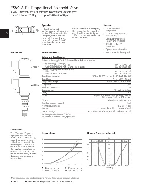
Screw-In Cartridge Valves E-VLSC-MC001-E5 January 2017B-332.A Where measurements are critical request certified drawings. We reserve the right to change specifications without notice.5510101515202025302530DB ACESV9-8-E - Proportional Solenoid Valve4-way, 3-position, screw-in cartridge, proportional solenoid valve Up to 11 L/min (2.9 USgpm) • Up to 250 bar (3600 psi)DescriptionThe ESV9 with E spool is a proportional four-way,three-position, direct acting,spool type solenoid valve with all ports closed in thede-energized position. This valve is ideal for moderate flow applications where an actuator needs to be con-trolled proportionally in both directions and stopped in any position.OperationIn the de-energized(center) position, all ports are blocked. When solenoid A is energized, flow is directed from port 3 to port 2 and from port 4 to port 1. Port 1 is not intended to be used as an inlet.When solenoid B is energized, flow is directed from port 3 to port 4 and from port 2 to port 1. Port 1 is not intended to be used as an inlet.Features• Highly engineered components• Compact design with low pressure drop• Designed for optimized linearity and hysteresis • IP69K ToughCoils™ compatible•Optional manual override •Industry standard cavity toolPerformance DataProfile View Pressure DropFlow vs. Current at 10 bar ∆PA - Port 3 to port 2B - Port 3 to port 4C - Port 4 to port 1D - Port 2 to port 1COIL B3124COIL ACurrent (A)5510101515202025302530D B ACScrew-In Cartridge Valves E-VLSC-MC001-E5 January 2017B-333.ABWhere measurements are critical request certified drawings. We reserve the right to change specifications without notice.ports to decay to tank pres-sure in the de-energized condition.A - Port 3 or port 2 energizedB - Port 3 to port 4 energizedC - Port 2 or port 1 energizedD - Port 2 to port 1 de-energizedCurrent (A)E - Port 4 to port 1 energizedF - Port 4 to port 1 de-energizedScrew-In Cartridge Valves E-VLSC-MC001-E5 January 2017B-334.A Where measurements are critical request certified drawings. We reserve the right to change specifications without notice.Model Code1ESV93*4*5*–––––1 FunctionESV9 - Proportional solenoid valve2 Size8 - 8 size3 Seal MaterialBlank - Buna-N V - Viton®28CodePort SizeHousing NumberAlumi ni um Steel0 Cartridge only A2G 1/4” BSPP 02-160747A3G 3/8” BSPP 02-160748A6H SAE 6 02-160749A8H SAE 8 02-160750S2G 1/4” BSPP 02-160753S3G 3/8” BSPP 02-160754S6T SAE 6 02-160751S8TSAE 802-160752See section J for housing details.6 Housing Material and PortsWARNINGAluminum housingscan be used for pres-sures up to 210 bar (3000 psi). Steel housings must be used for operating pressures above210 bar (3000 psi).EF4 Spool Center ConditionCOIL B3124COIL A24COIL BCOIL A6***5 Manual Override Option0 - No manual overrideM - Manual override, push pull typeFor valve dimensions with manual override, see pages B873.7 Coil Voltage and T ype000 - No coil012D - 12V DC without diode 024D - 24V DC without diode 012B - 12V DC with diode 024B - 24V DC with diode8 Connection T ypeBlank - No coilN - Deutsch male, DT04-2P , integrated G - DIN 43650 W - Flying leadY - Amp Jr (DC Only) Mating Connector: AMP 963040-3 or equivalentD0 - MetriPackR 150 Male, Integrated (DC Only) Mating Connector: Delphi 12052641See Section C for coil details .1 T hese model digits are not stamped onthe valve.10 Coil Special Feature00 - None11 Valve Special Features 100 - None(Only required if valve has special features omitted if "00".)12 Design CodeA - Design code 009 Coil SeriesBlank - No coil P - P SeriesToughCoils™ 23 W11**12A10**8*9*7****Screw-In Cartridge Valves E-VLSC-MC001-E5 January 2017B-335.AWhere measurements are critical request certified drawings. We reserve the right to change specifications without notice.Dimensions mm (inch)Torque cartridge in aluminum housing 34-41 Nm (25.0 - 30.0 ft. lbs.) and 34-41 Nm (25.0 - 30.0 ft. lbs. ) in a steel housingWhen solenoid valve isordered without coils, it will be supplied with coil spacer and coil nut.Spare PartsCoil Nut for MO 565559Coil Nut without MO 565558Coil Spacer02-186730WARNINGMaintain 5-8 Nm (4-6 ft lbs) maximumtorque on coil nut.Over tightening may causevalve failure.31.8[1.25]ESV9-8 without MOESV9-8 with MOScrew-In Cartridge Valves E-VLSC-MC001-E4 May 2016B-332.A Where measurements are critical request certified drawings. We reserve the right to change specifications without notice.Flow - lpm P r e s s u r e D r o p - p s i5ESV9-10-E - Proportional Solenoid Valve4-way, 3-position, screw-in cartridge, proportional solenoid valve Up to 22 L/min (5.8 USgpm) • Up to 250 bar (3600 psi)DescriptionThe ESV9 with E spool is a proportional four-way,three-position, direct acting, spool type solenoid valve with all ports closed in the de-energized position. This valve is ideal for moderate flow applications where an actuator needs to be con-trolled proportionally in both directions and stopped in any position.OperationIn the de-energized(center) position, all ports are blocked. When solenoid A is energized, flow is directed from port 3 to port 2 and from port 4 to port 1. Port 1 is not intended to be used as an inlet.When solenoid B is energized, flow is directed from port 3 to port 4 and from port 2 to port 1. Port 1 is not intended to be used as an inlet.Features•Highly engineered components•Compact design with low pressure drop•Designed for optimized linearity and hysteresis •IP69K Large ToughCoils™ compatible•Optional manual override •Industry standard cavity toolPerformance DataProfile ViewA - Port 3 to port 2B - Port 3 to port 4C - Port 4 to port 1D - Port 2 to port 1“Coil B”3421COIL B3124COIL A510152025Coil B Coil A2.00 1.501.000.500.000.50 1.00 1.502.00F l o w (l p m )Current (A)Screw-In Cartridge Valves E-VLSC-MC001-E4 May 2016B-333.AWhere measurements are critical request certified drawings. We reserve the right to change specifications without notice.ESV9-10-F - Proportional Solenoid Valve4-way, 3-position, screw-in cartridge, proportional solenoid valve Up to 22 L/min (5.8 USgpm) • Up to 250 bar (3600 psi)DescriptionThe ESV9 with F spool is a proportional four way, three position, direct acting, spool type solenoid valve. In the de-energized condition Port 2 and 4 are open to tank with the inlet port 3 blocked. This valve is ideal formoderate flow applications where an actuator needs to be moved in both directions and stopped in any position while allowing the service ports to decay to tank pres-sure in the de-energized condition.OperationIn the de-energized (cen-ter) position, port 1, port 2, and port 4 are open to each other while port 3 is blocked. When solenoid A is energized, flow isdirected from port 3 to port 2 and from port 4 to port 1. When solenoid B is energized, flow is directed from port 3 to port 4 and from port 2 to port 1.Features•Highly engineered components•Compact design with low pressure drop•Designed for optimized linearity and hysteresis •IP69K Large ToughCoils™ compatible•Optional manual override •Industry standard cavity tool .Performance DataProfile View Pressure DropA - Port 3 or port 2 energizedB - Port 3 to port 4 energizedC - Port 2 or port 1 energizedD - Port 2 to port 1 de-energizedFlow - Ipm 0510152025303540051015202530354045505560ABC E DFP r e s s u r e D r o p - b a r“Coil B”“Coil A”342124COIL BCOILA510152025Coil B Coil A2.00 1.501.000.500.000.501.001.502.00F l o w (l p m )Current (A)E - Port 4 to port 1 energizedF - Port 4 to port 1 de-energizedFlow vs. Current at 10 bar ∆PScrew-In Cartridge Valves E-VLSC-MC001-E4 May 2016B-334.A Where measurements are critical request certified drawings. We reserve the right to change specifications without notice.Up to 22 L/min (5.8 USgpm) • Up to 250 bar (3600 psi)Model Code1ESV93*4*5*–––––1 FunctionESV9 - Proportional solenoid valve2 S ize10 - 10 size3 S eal MaterialBlank - Buna-N V - Viton®210Code Port SizeHou s ing NumberAluminium Steel0 Cartridge only A2G 1/4” BSPP 02-185804A3G 3/8” BSPP 02-185805A6H SAE 6 02-185802A8H SAE 8 02-185803S2G 1/4” BSPP 02-175139S3G 3/8” BSPP 02-175140S6T SAE 6 02-175137S8TSAE 802-175138See section J for housing details.6 Housing Material and PortsWARNINGAluminum housingscan be used for pres-sures up to 210 bar (3000 psi). Steel housings must be used for operating pressures above210 bar (3000 psi).EF4 Spool Center ConditionCOIL B3124COIL A24COIL BCOILA6***5 Manual Override Option0 - No manual overrideM - Manual override, push pull typeFor valve dimensions with manual override, see pages B873.7 Coil Voltage and T ype000 - No coil012D - 12V DC without diode 024D - 24V DC without diode 012B - 12V DC with diode 024B - 24V DC with diode8 Connection T ypeBlank - No coilN - Deutsch male, DT04-2P , integrated G - DIN 43650 W - Flying leadY - Amp Jr (DC Only) Mating Connector: AMP 963040-3 or equivalentD0 - MetriPackR 150 Male, Integrated (DC Only) Mating Connector: Delphi 12052641See Section C for coil details .1 T hese model digits are not stamped onthe valve.10 Coil Special Feature00 - None11 Valve Special Features 100 - None(Only required if valve has special features omitted if "00".)12 Design CodeA - Design code 009 Coil S eriesBlank - No coil L - L Series Large ToughCoils™ 28 W11**12A10**8*9*7****Screw-In Cartridge Valves E-VLSC-MC001-E4 May 2016B-335.ABWhere measurements are critical request certified drawings. We reserve the right to change specifications without notice.Up to 22 L/min (5.8 USgpm) • 250 bar (3000 psi)Dimensions mm (inch)Torque cartridge in aluminum housing 47 - 54 Nm (34.7 - 39.8 ft. lbs.) and 56 - 62 Nm (41.3 - 45.7 ft. lbs. ) in a steel housingValve is shown with large tough coil.Note: The ESV9-10 is shipped with a spacer (6038409-001) to be used with the Large Tough Coil. Spacer is not needed when used with the EN490 coil.When solenoid valve isordered without coils, it will be supplied with coil spacer and coil nut.Spare PartsCoil Nut for MO 6038813-001Coil Nut without MO 02-148332Coil Spacer6038409-001WARNINGMaintain 5-8 Nm (4-6 ft lbs) maximumtorque on valve tube nut. Over tightening may cause valve failure.1。
一些国外螺纹插装阀生产商介绍
一些国外螺纹插装阀生产商介绍一些国外螺纹插装阀生产商介绍张海平张海平 20120122-1212--191.HYDRAFORCE(1.HYDRAFORCE(海德福斯海德福斯海德福斯))公司公司1983年,当时世界上规模最大的螺纹插装阀专业生产厂Modular公司被Vickers公司并购。
两年后,3个当年Modular的员工建立了HYDRAFORCE公司。
至今,HF在美国的厂房达13,000m²,在英国的厂房也有4,650m²。
2003年销售额已达90MUS$,螺纹插装阀的生产规模又是世界第一。
以前产品基本以中压为主,无平衡阀。
现在也已开发了很多高压的阀。
孔型以ICC 系列为主。
2.SUN 公司公司SUN 升旭公司建立于1970年。
1997年上市。
目前,在美国的Florida、Kansas、英国、德国、法国、韩国、印度多处有子公司。
1998年与台湾橡达公司合作,在上海松江建立了一个合资子公司。
2011年年初宣布,退出了合资,建立了它自己在中国的销售办事处。
橡达公司仍然是SUN 产品的代理商。
2004年螺纹插装阀的产能就达到5.8万件/周。
SUN 公司很迅速地从金融危机中走出来。
2010年销售额达到了2006年的水平,约为150MUS$,税后纯利润达12%。
公司销售收入约75%来自螺纹插装阀,25%则来自阀块和集成块。
产品约70%供应移动液压,30%固定液压。
孔型自成一格,公制英制螺纹兼有。
3.Sterling Hydraulics 公司公司母公司在英国的Crewkerne。
以前生产汽车零件,60年代后期开始生产螺纹插装阀。
90年代初,美国Waterman公司的主任设计师Kolchinski先生到了Sterling公司美国分部,开始开发电磁阀。
95年形成全系列。
他设计的电磁线圈后被Parker公司称为Super-Coil超级线圈。
插装阀生产能力达到1.5百万件/年。
30%供应建筑机械公司Caterpillar。
螺纹插装阀介绍之二_平衡阀
螺纹插装阀介绍之二螺纹插装阀介绍之二 平衡阀平衡阀张海平张海平摘要摘要::本文概述了选用平衡阀时必须注意的特性,介绍了不同类型的制成螺纹插装形式的平衡阀,它们的性能和工作原理。
关键词关键词::螺纹插装阀, 平衡阀0.概述概述平衡阀(Counterbalance Valve),又称负载控制阀(Load Control Valve),也有称运动控制阀(Motion Control Valve),其实它的德文名称负载保持阀(Lasthaltensventil),或下降刹车阀(Senkbremsventil)更贴近其关键功能,但考虑到国内习惯,本文中还是称平衡阀。
图0-1 负向负载的控制如所周知,液压对正向负载力大无穷,但对负向负载就相形见绌了。
开式回路中原则上只能采取节流的方法,被动地控制,如图0-1。
若负载力幅度多变而要求速度不变,在一定范围内可以采用二通流量阀或更复杂一些,带反馈的比例节流阀等。
但若负载力不仅幅度多变且有时会降到接近零甚至时负时正,如图0-2,则单靠普通被动节流的方法就不行了。
而这种情况在工程液压中很常见,这就是为什么平衡阀在工程液压中会十分广泛地被应用。
如液压升降工作台(图0-3)中,平衡阀被用于软启动、软停止、平稳运动,以保证可靠地停在每个希望的位置,即使管道破裂也不会下沉。
在履带式行走机械(图0-4)中使用两个平衡阀,用于避免在行进中出现不希望的前冲或后退。
在绞车(图0-5)中,一个平衡阀与一个液控方向阀结合,以保证在希望工作时,先松煞车再动作;在不希望工作时,可靠地停留在任意位置。
因为平衡阀消耗能量甚多,容易引起过热,通常不用于低压系统(<5 MPa),也不用于闭环系统。
摆动负载图0-2摆动负载液压升降工作台 图0-4履带式行走机械履带式行走机械图0-3液压升降工作台绞车5 绞车图0-5绞车功能0.1功能平衡阀可以说是集三阀于一身,参见图0.1-1。
用平衡阀控制负向负载0.1--1用平衡阀控制负向负载图0.1一是作为单向阀(2→1)。
生锈防腐型螺纹电流保护器Eaton PDG24N0225P3YJ商品说明说明书
Eaton PDG24N0225P3YJEaton Power Defense molded case circuit breaker, Globally Rated, Frame 2, Four-pole (100% N), 225A, 85kA/480V, PXR25 LSIG w/ Modbus RTU, CAM Link, ZSI and Relays, Standard Line and LoadGeneral specificationsEaton Power Defense molded case circuit breakerPDG24N0225P3YJ 78667933861288.9 mm 152.4 mm 139.5 mm 2.46 kg Eaton Selling Policy 25-000, one (1) year from the date of installation of theProduct or eighteen (18) months from thedate of shipment of the Product,whichever occurs first.RoHS Compliant CCC MarkedIEC 60947-2Product NameCatalog Number UPCProduct Length/Depth Product Height Product Width Product Weight WarrantyCompliancesCertifications225 AComplete breaker 2Four-pole (100% N)PD2 GlobalClass APXR 25 LSIGModbus RTU and CAM Link600 Vac600 V100% neutral protectionStandard Line and Load85 kAIC at 480 Vac22 kAIC Icu @125 Vdc70 kAIC Icu/ 50 kAIC Ics/ 154 kAIC Icm @440V (IEC)70 kAIC Icu/ 70 kAIC Ics/ 154 kAIC Icm @380-415V (IEC) 10 kAIC Icu/ 5 kAIC Ics/ 21 kAIC Icm @690V (IEC)22 kAIC Icu @250 Vdc30/25 kAIC Icu/ 15/13 kAIC Ics @525V South Africa (IEC) 85 kAIC @480V (UL)150 kAIC Icu/ 100 kAIC Ics/ 330 kAIC Icm @240V (IEC)30/25 kAIC @600V (UL/CSA)150 kAIC @240V (UL)65 kAIC Icu/ 40 kAIC Ics/ 143 kAIC Icm @480V Brazil (IEC) 25 kAIC @600V (UL/CSA)Eaton Power Defense MCCB PDG24N0225P3YJ 3D drawingPower Xpert Protection Manager x64Power Xpert Protection Manager x32Consulting application guide - molded case circuit breakersPower Defense technical selling bookletPower Defense brochurePower Defense molded case circuit breaker selection poster Power Defense molded case circuit breakers - Frame 2 product aidMolded case circuit breakers catalogAmperage RatingCircuit breaker frame type FrameNumber of poles Circuit breaker type ClassTrip Type CommunicationVoltage ratingVoltage rating - maxProtectionTerminalsInterrupt rating Interrupt rating range 3D CAD drawing package Application notesBrochuresCatalogsPower Xpert Release trip units for Power Defense molded case circuit breakersCertification reportsPDG4 CCC certificationPDG4 CB reportPDG2 CB reportEU Declaration of Conformity - Power Defense molded case circuit breakersInstallation instructionsPower Defense Frame 2 clamp terminal (steel), 20A, 4 pole instructions - IL012246EN H04Power Defense Frame 2 box terminal (aluminum), 225A, 4 pole instructions - IL012235EN H04Power Defense Frame 2 screw terminal_end cap kit, 225A, 3 pole instructions - IL012258EN H01Power Defense Frame 1 IEC and Frame 2 Rotary Mechanism with NFPA Handle Attachment Instructions (IL012260EN).pdfPower Defense Frame 2 tunnel terminal (aluminum), 50A, 4 pole instructions - IL012236EN H04Power Defense Frame 2 box terminal (steel), 100A, 4 pole instructions - IL012234EN H04Power Defense Frame 2 shunt trip UVR instructions - IL012130EN Power Defense Frame 2 global terminal shield, 4 pole - IL012330EN Power Defense Frame 2 terminal kit - PDG2X3(2)(4)TA150RF instructions - IL012244EN H01Power Defense Frame 2 terminal kit - PDG2X3(2)(4)TA225RF instructions - IL012245EN H01Power Defense Frame 2/3/4/5/6 voltage neutral sensor module wiring instructions – IL012316ENPower Defense Frame 2 multi wire connector kit -PDG2X3(2)(4)TA2253W instructions - IL012243EN H01Power Defense Frame 1-2-3-4 IP door barrier assembly instructions -IL012278ENPower Defense Frame 2 tunnel terminal (aluminum), 100A, 4 pole instructions - IL012237EN H04Power Defense Frame 2 locking devices and handle block instructions - IL012149ENPower Defense Frame 2 tunnel terminal kits - PDG2X1TA225K instructions- IL012239EN H01Power Defense Frame 2 tunnel terminal (aluminum), 150A, 4 pole instructions - IL012238EN H04Power Defense Frame 2 multi wire connector kit -PDG2X3(2)(4)TA2256W instructions - IL012242EN H01Power Defense Frame 2 PDG2 and PDC(E)9 breaker instructions -IL012106ENPower Defense Frame 2 Bell Alarm Switch Instructions (IL012154EN).pdf Power Defense Frame 2 bell alarm switch instructions - IL012154EN Installation videosPower Defense Frame 2 TMTU Aux, Alarm, ST and UVR Animated Instructions.rhPower Defense Frame 2 Bell Alarm with PXR Animated Instructions.pdf.rh Power Defense Frame 2 withTMTU, Shunt Trip_UVR Animated Instructions.rhMultimediaPower Defense Frame 3 Variable Depth Rotary Handle Mechanism Installation How-To VideoPower Defense Frame 2 Variable Depth Rotary Handle Mechanism Installation How-To VideoPower Defense Frame 2 Aux, Alarm, Shunt Trip, and UVR How-To Video Power Defense Frame 2 Direct Rotary Handle Mechanism Installation How-To VideoEaton Power Defense for superior arc flash safetyPower Defense Frame 5 Trip Unit How-To VideoPower Defense molded case circuit breakersPower Defense BreakersPower Defense Frame 6 Trip Unit How-To VideoSpecifications and datasheetsEaton Specification Sheet - PDG24N0225P3YJTime/current curvesPower Defense time current curve Frame 2 - PD2White papersMolded case and low-voltage power circuit breaker healthIntelligent circuit protection yields space savingsSingle and double break MCCB performance revisitedIntelligent power starts with accurate, actionable dataMaking a better machineSafer by design: arc energy reduction techniquesMolded case and low-voltage breaker healthEaton Corporation plc Eaton House30 Pembroke Road Dublin 4, Ireland © 2023 Eaton. All Rights Reserved. Eaton is a registered trademark.All other trademarks areproperty of their respectiveowners./socialmedia。
螺纹插装阀品牌
螺纹插装阀品牌见网友发过一个插装阀品牌的帖子,以我个人的理解,发一个常见螺纹插装阀品牌的帖子,也许有一些遗漏的好产品,好品牌,欢迎广大行业人士跟帖,探讨一下.此液压螺纹插装阀不包括二通插装阀.第一梯队插装阀:产销超过或者接近一亿美金的,质量跟销量的综合比较: Hydraforce:行业第一的销售业绩说明了该产品在中低压产品中的性价比很高,该阀仿照以前Modular产品来做的,但是平衡阀基本上没有做,现在发布的小流量平衡阀,高压阀也在陆续发布.Parker:旗下产品sterling,waterman,fluid power system的整合,机械阀跟电磁阀的强强组合,绝对是插装阀质量最好,产品最全的厂家之一Eaton:螺纹插装阀主要是Modular,IH的产品,产品很丰富,阀的全面程度与parker差不多.Sun hydraulics:位于世界第二销量的厂家,机械阀绝对是行业老大,但是电磁阀不是很全面,也可能是思路的问题,先导电磁阀加逻辑阀来实现大流量电磁阀.Comatrol (Sauer danfoss):收购整合了丹麦danfoss fluid control,全世界最早做插装阀的品牌之一,美国co mand control,意大利comatrol,具有很全面的插装阀产品,特点是比例流量控制及方向控制.现在comatrol品牌全球独立销售,估计未来会更好.Rexroth (Oil control):在欧洲,oil control最早是danfoss fluid control的代理商,慢慢开始生产插装阀,最后收购了tarp及edi后,实力得到了很大提高,被rexroth收购以后,前景应该更好.Bucher:收购瑞士的Hydrotechnik Frutigen AG,不包含CCC.Hydac:挖机先导,风电液压用量很大.第二梯队插装阀:以下品牌不做论述Delta power:Deltrol:Bucher(ccc):Walvoil(oleostar):Hydra control(nem):Argo hytos:主要以cetop标准阀为主,插装阀部分英国一厂家给贴牌.第三梯队插装阀:除上述品牌以外的各种意大利品牌:luen,atlantic,cbf,hbs等很多…第四梯队插装阀:武汉机械(Winner):克泰:海宏:。
Eaton 螺纹护电设备安装说明说明书
Installation Instructions for Eaton Surge Protective Devices XXCFXXX30 and XXCFXXX60ContentsDescription Page1.0 Setup (2)1.1 Before Installation (2)1.2 Installation (2)1.3 Wiring (2)1.3.1 Series Wiring Applications (3)1.3.2 Parallel Wiring Applications (3)1.4 Apply Power (3)1.5 Specifications (3)1.6 Warranty (4)XXCF12030XXCF120602Instruction Manual IM01005025EEffective April 2014Installation Instructions forEaton SurgeEATON WARNINGHAZARDOUS VOLTAGES PRESENTIMPROPER INSTALLATION OR MISAPPLICATION OF THESE DEVICES MAY RESULT IN SERIOUS INJURY TO INSTALLER AND/OR DAMAGE TO ELECTRI-CAL SYSTEM OR RELATED EQUIPMENT. READ AND UNDERSTAND ALL INSTRUCTIONS BEFORE BEGINNING INSTALLATION. PROTECTIVE EYE-WEAR SHOULD BE WORN WHENEVER WORKING AROUND HAZARDOUS VOLTAGES.NOTICEALL INSTRUCTIONS AND MEASUREMENTS MUST BE COMPLETED BY A LICENSED/QUALIFIED ELECTRICIAN IN ACCORDANCE WITH THE U.S. NATIONAL ELECTRICAL CODE, STATE AND LOCAL CODES OR OTHER APPLI-CABLE COUNTRY CODES. THE U.S. NATIONAL ELECTRICAL CODE AND STATE AND LOCAL REQUIREMENTS (OR OTHER APPLICABLE COUNTRY CODES) SUPERSEDE THIS INSTRUCTION.Catalog NumberAmpsVoltage RangeMode VPR MCOV In SCCRPeak Surge Current PhaseXXCF1203033048 - 149 Vdc 1 100 -127 VacL-N5001505kA 10kA120kAL-G 500150N-G 500150XXCF1206036048 - 149 Vdc 1 100 -127 VacL-N5001505kA 10kA 120kA L-G 500150N-G500150Catalog NumberAmpsVoltage RangeMode MCOV In SCCRPeak Surge Current Phase XXCF24030230150 - 300 Vdc 1200 - 240 VacL-N, L-G, N-GN/A N/A N/A 80kAXXCF24060260150 - 300 Vdc 1200 - 240 VacL-N, L-G, N-GN/AN/AN/A80kA1 UL 1449 3rd Edition does not list SPD products rated less than 100 Vac or DC voltages.21283 4th Edition, EMI Filter 3UL 1449 3rd Edition, UL 1283 5th Edition1.0 SetupVerify system voltages do not exceed those listed in Section 1.5, Specifications.•All AC measurements should be completed with an RMS voltme-ter.• All DC measurements should be completed with a DC voltmeter. •DO NOT INSTALL FILTER IF MEASURED VOLTAGE EXCEEDS MAXIMUM OPERATING LIMITS.Choose location for filter installation so that maximum separation can be maintained between input leads, output leads and ground leads.1.1 Before InstallationREMOVE POWER FROM ELECTRICAL SYSTEM BEFORE MOUNTING FILTER.•Filter MUST be mounted within enclosure to assure personnel safety from exposed terminals.IMPORTANT:FILTER SHOULD BE LOCATED SO THAT THE SHORTEST POSSIBLE CONDUC-TOR LENGTH MAY BE USED.•Filter should be mounted to allow maximum separation between input and output wiring.•Filter contains no position-oriented components and can be mounted upside down or sideways.•Filter should be placed in electrical circuit so that it is the last device in the circuit before equipment to be protected.1.2 InstallationFILTER MUST BE CONNECTED TO ELECTRICAL SYSTEM WITH A CIRCUIT BREAKER:•1 - Single Pole / Single Throw 40A or 100A circuit breaker(s), The Interrupting Rating of the Circuit Breaker Shall Not Be Less Than the Available Fault Current. Circuit Breaker Ratings of 40A, 240V/415V, 10kA Min. AIC Rating for 30 amp devices and Circuit Breaker Ratings of 100A, 480V, 10kA Min. AIC Rating for 60 amp devices.Note: Pre-existing breaker(s) of the rated load size may be utilized if provisions for multi-conductor connections are made according to N.E.C. 110-14A.•If Neutral wire is to be utilized as L2/NEU, then circuit breaker should be provided for that phase.REMOVE POWER FROM ELECTRICAL SYSTEM BEFORE INSTALL -ING FILTER.Mechanically mount filter.•Mount filter using mounting flange holes or optional DIN bracket listed below.•Filter should be mounted to allow maximum separation between input and output wiring.•Filter contains no position oriented components and can be mounted upside down or sideways.•Filter should be placed in electrical circuit so that it is the last device in circuit before equipment to be protected.•Mounting bracket and foot adaptable to DIN Rail systems DIN EN 50022, DIN EN 50035 and DIN EN 50045 are available through Eaton Order Desk and can be ordered as an option (order part # 420-9100 for 30A or order part # 420-9200 for 60A).1.3 WiringNOTICEAN INSULATED GROUNDING CONDUCTOR THAT IS IDENTICAL IN SIZE AND INSULATION MATERIAL AND THICKNESS TO THE GROUNDED AND UNGROUNDED CIRCUIT SUPPLY CONDUCTORS, EXCEPT THAT IT IS GREEN WITH OR WITHOUT ONE OR MORE YELLOW STRIPES, IS TO BE INSTALLED AS PART OF THE CIRCUIT THAT SUPPLIES THE FILTER. SEE TABLE 250-122 OF THE NATIONAL ELECTRIC CODE (NEC) REGARDING THE APPROPRIATE SIZE OF THE GROUNDING CONDUCTOR.THE GROUNDING CONDUCTOR IS TO BE GROUNDED TO EARTH AT THE SERVICE EQUIPMENT OR OTHER ACCEPTABLE BUILDING EARTH GROUND SUCH AS THE BUILDING FRAME IN THE CASE OF HIGH-RISE STEEL FRAME STRUCTURE.ANY ATTACHMENT-PLUG RECEPTACLES IN THE VICINITY OF THE FILTER ARE TO BE GROUNDING TYPE, AND THE GROUNDING CONDUCTORS SERV-ING THESE RECEPTACLES ARE TO BE CONNECTED TO EARTH GROUND AT THE SERVICE EQUIPMENT OR OTHER ACCEPTABLE BUILDING EARTH GROUND SUCH AS THE BUILDING FRAME IN THE CASE OF HIGH-RISE STEEL FRAME STRUCTUREPRESSURE TERMINAL OR PRESSURE SPLICING CONNECTORS AND SOL-DERING LUGS USED IN THE INSTALLATION OF THE FILTER SHALL BE IDENTIFIED AS BEING SUITABLE FOR THE MATERIAL OF THE CONDUC-TORS. CONDUCTORS OF DISSIMILAR METALS SHALL NOT BE INTERMIXED IN A TERMINAL OR SPLICING CONNECTOR WHERE PHYSICAL CONTACT OCCURS BETWEEN DISSIMILAR CONDUCTORS UNLESS THE DEVICE IS IDENTIFIED FOR THE PURPOSE AND CONDITIONS OF USE.3Instruction Manual IM01005025EEffective April 2014Installation Instructions for Eaton SurgeEATON NOTICECONDUCTORS SHOULD BE TWISTED TOGETHER TO REDUCE IMPEDANCE FACTOR. EXCESSIVE WIRE LENGTH AND SHARP BENDS DEGRADE FIL-TER PERFORMANCE; THEREFORE, AVOID EXCESSIVE WIRE LENGTH AND SHARP BENDS.1.3.1 Series Wiring Applications•Connect incoming system GROUND wire to terminal labeled GND on unprotected end (labeled as LINE ).•Connect load side GROUND wire to terminal labeled GND on protected end (labeled as EQUIP ).For AC Applications•Connect incoming system NEUTRAL wire to terminal labeled L2/NEU on unprotected end (labeled as LINE ).•Connect load side NEUTRAL wire to terminal labeled as L2/NEU on protected end (labeled as EQUIP ).•Connect incoming system HOT wire to terminal labeled L1 on unprotected end (labeled as LINE ).•Connect load side HOT wire to terminal labeled as L1 on protected end (labeled as EQUIP ).For DC Applications•Connect incoming system NEGATIVE wire to terminal labeled L2/NEU on unprotected end (labeled as LINE ).•Connect load side NEGATIVE wire to terminal labeled as L2/NEU on protected end (labeled as EQUIP ).•Connect incoming system POSITIVE wire to terminal labeled L1 on unprotected end (labeled as LINE ).•Connect load side POSITIVE wire to terminal labeled as L1 on protected end (labeled as EQUIP ).1.3.2 Parallel Wiring ApplicationsIMPORTANT:FILTER SHOULD BE LOCATED SO THAT THE SHORTEST POSSIBLE CON-DUCTOR LENGTH MAY BE USED. CONDUCTORS SHOULD BE TWISTED TOGETHER TO REDUCE IMPEDANCE FACTOR. EXCESSIVE WIRE LENGTH AND SHARP BENDS DEGRADE FILTER PERFORMANCE; THEREFORE, AVOID EXCESSIVE WIRE LENGTH AND SHARP BENDS.•Connect incoming system GROUND wire to terminal labeled GND on unprotected end (labeled as LINE ).For AC Applications•Connect incoming system NEUTRAL wire to terminal labeled L2/NEU on unprotected end (labeled as LINE ).•Connect incoming system HOT wire to terminal labeled L1 on unprotected end (labeled as LINE ).For DC Applications•Connect incoming system NEGATIVE wire to terminal labeled L2/NEU on unprotected end (labeled as LINE ).•Connect incoming system POSITIVE wire to terminal labeled L1 on unprotected end (labeled as LINE ).ote:N For ungrounded or isolated control transformer secondary, DO NOT CONNECT Ground terminal on either LINE or EQUIP side.1.4 Apply PowerApply power to system. Indicator light(s) should glow and alarm contacts should move to normal state. If the light does not glow, remove power and contact supplier.1.5 SpecificationsDescriptionRatingsAgency ApprovalsXXCF24030, XXCF24060XXCF12030, XXCF12060UL1283 4th Edition, EMI FilterUL1449 3rd Edition, UL1283 5th Edition Type 2 SPD Terminal Connections 30A 60AWire clamping terminals, 10-18 AWG (UL), 10-22 AWG (CSA) Torque 12 in-lbStud lug terminals. Torque 60 lb-in Operating Temperature -40F(-40C) to +140F(+60C)System voltages DC AC 48 - 149 Vdc, 150 - 300 Vdc,100 - 127 Vac, 200 - 240 Vac Amps 30A, 60ACatalog Number XXCF12030XXCF12060Circuit Breaker40A, 240V/415V, 10kA Min. AIC Rating 100A, 480V, 10kA Min. AIC Rating Input Power Frequency 50/60 Hz Warranty 2 Years RoHS CompliantYesInstruction Manual IM01005025E Effective April 2014Installation Instructions forEaton SurgeEatonElectrical Sector1000 Eaton Boulevard Cleveland, OH 44122United States877-ETN-CARE (877-386-2273) © 2014 EatonAll Rights ReservedPrinted in USAPublication No. IM01005025E / TBG000468 April 2014Eaton is a registered trademark.All other trademarks are property of their respective owners.Figure 4. XXCFXXX30 Product DimensionsFigure 5. XXCFXXX60 Product Dimensions 1.6 WarrantyEaton warrants these products for a period of 2 years from the date of delivery to the purchaser, 5 years if the product is registered with Eaton, to be free from defects in both workmanship and materials. Eaton assumes no risk or liability for results of the use of the prod-ucts purchased from it, including but without limiting the generality of the foregoing; (1) The use in combination with any electrical or electronic components, circuits, systems, assemblies, or any other materials or substances; (2) Unsuitability of any product for use in any circuit or assembly.Purchaser’s right under the warranty shall consist solely of requiring Eaton to repair, or at Eaton’s sole discretion, replace, free of charge, F.O.B. factory, and defective items received at said factory or failure to give any advice or recommendations by Eaton shall not constitute any warranty by or impose any liability upon Eaton. The foregoing constitutes the sole and exclusive liability of Eaton AND IS IN LIEU OF ANY AND ALL OTHER WARRANTIES EXPRESSED, IMPLIED OR STATURORY AWS TO THE MERCHANTABILITY, FITNESS FOR PURPOSE SOLD, DESCRIPTION, QUALITY, PRODUCTIVENESS OR ANY OTHER MATTER.In no event shall Eaton be liable for special or consequential dam-ages or for delay in performance of the warranty.This warranty does not apply if the product has been misused, abused, altered, tampered with, or used in applications other than specified on the nameplate. At the end of the warranty period, Eaton shall be under no further warranty obligation expressed or implied.The product covered by this warranty certificate can only be repaired or replaced by the factory. For help on troubleshooting the Critical Protection Product, or for warranty information, call 1-800-809-2772, Option 4, sub-option 2. Repair or replacement units will be returned collect. If Eaton finds the return to be a manufacturer’s defect, the product will be returned prepaid.。
- 1、下载文档前请自行甄别文档内容的完整性,平台不提供额外的编辑、内容补充、找答案等附加服务。
- 2、"仅部分预览"的文档,不可在线预览部分如存在完整性等问题,可反馈申请退款(可完整预览的文档不适用该条件!)。
- 3、如文档侵犯您的权益,请联系客服反馈,我们会尽快为您处理(人工客服工作时间:9:00-18:30)。
1
© 2013 Eaton. All Rights Reserved.
伊顿的业务
电气集团 134亿美元*
电气产品
系统及服务
* 2013年包括库柏的年度销售
工业集团 86亿美元
液压 宇航 车辆
© 2013 Eaton. All Rights Reserved.
© 2013 Eaton. All Rights Reserved.
18
螺纹插装阀产品线(压力控制)
减压阀:PRV2/12、1PA
© 2013 Eaton. All Rights Reserved.
19
螺纹插装阀产品线(流量控制)
节流阀:FAR1、NV1、FCV6/7/11 分流阀:FDC1/3/11
© 2013 Eaton. All Rights Reserved.
5
Mobile
八个核心市场板块
Agriculture & Forestry 农业和林业 机械
Construction & Mining建筑及矿用 机械
Material Handling 物料搬运
Commercial Vehicles 商用和军用 车辆
© 2013 Eaton. All Rights Reserved.
22
螺纹插装阀产品线(方向控制)
梭阀:1SH、DSV1/2/4、1HSH
© 2013 Eaton. All Rights Reserved.
23
螺纹插装阀产品线(负载控制)
平衡阀:1CE、1CEBD、CBV1/2
© 2013 Eaton. All Rights Reserved.
© 2013 Eaton. All Rights Reserved.
7
© 2013 Eaton. All Rights Reserved.
8
© 2013 Eaton. All Rights Reserved.
9
伊顿液压中国区布局
Jining 济宁
(5) Manufacturing Sites 生产制造基地
3
一个伊顿 – 产品的融合
完美的整体解决方案
液压 电器
© 2013 Eaton. All Rights Reserved.
4
一个伊顿 – 品牌的融合
多年来,通过并购、合资和 独资等形式,伊顿将全球多 个久负盛名的品牌纳入旗下 ,并对其进行有效整合,从 而提升了专业技能、扩大了 产品和服务组合,打造了一 个令人信赖的品牌,满足任 一动力管理需求。
24
螺纹插装阀产品线(负载控制)
© 2013 Eaton. All Rights Reserved.
25
螺纹插装阀产品线(逻辑单元)
逻辑阀:DPS2
© 2013 Eaton. All Rights Reserved.
26
螺纹插装阀产品线(比例控制)
比例阀:EPV16、PDR2、ERV1
© 2013 Eaton. All Rights Reserved.
Oil & Gas, Marine 石油及天然气-海事
Discrete Manufacturing 独立制造设备
Processing 流程生产设备
Alternative Energy 可替代能源
Stationary
© 2013 Eaton. All Rights Reserved.
6
伊顿主要的液压产品线
© 2013 Eaton. All Rights Reserved.
Shanghai
Pump, Valve, HPU, Industrial Brake and Clutch 泵、阀、动力站、工业刹车和离 合器 Ningbo 宁波
Fitting/Adapter 胶管、接头
10
© 2013 Eaton. All Rights Reserved.
27
螺纹插装阀产品线(螺纹插装阀组)
© 2013 Eaton. All Rights Reserved.
28
螺纹插装阀腔孔规格(常规)
© 2013 Eaton. All Rights Reserved.
29
螺纹插装阀腔孔规格(非常规)
© 2013 Eaton. All Rights Reserved.
© 2013 Eaton. All Rights Reserved.
20
螺纹插装阀产品线(方向控制)
电磁阀:SV1/3/4/11/13、SBV11
© 2013 Eaton. All Rights Reserved.
21
螺纹插装阀产品线(方向控制)
单向阀:CV1/2/3/11/13、4CK、POC1
(28) Sales Offices 销售办事处 (4) Engineering Centers 工程设计中心
Pump, Steering Control Unit, Motor 泵,转向器,马达
Luzhou 泸州
Fitting / Adapter 胶管/接头
Hong Kong
Trading Center 贸易中心
30
螺纹插装阀的应用
© 2013 Eaton. All Rights Reserved.
31
螺纹插装阀的应用
© 2013 Eaton. All Rights Reserved.
32
螺纹插装阀的应用
© 2013 Eaton. All Rights Reserved.
33
螺纹插装阀的应用
© 2013 Eaton. All Rights Reserved.
15
螺纹插装阀产品线
© 2013 Eaton. All Rights Reserved.
16
螺纹插装阀产品线(压力控制)
溢流阀:RV1/3/5/8/11、1L Eaton. All Rights Reserved.
17
螺纹插装阀产品线(压力控制)
顺序阀:PSV1/4/8/10/11
11
© 2013 Eaton. All Rights Reserved.
12
© 2013 Eaton. All Rights Reserved.
13
© 2013 Eaton. All Rights Reserved.
14
螺纹插装阀产品线
© 2013 Eaton. All Rights Reserved.
34
© 2013 Eaton. All Rights Reserved.
35
张诚(应用工程师) 18918681667 0574-88368366 chengzhang@