BF693xA通信协议说明_V1.0
RFID模块板子JYLD6900自由口协议通信说明

RFID模块板子JY-LD6900通用自由口协议通信说明RFID模块板子JY-LD6900是健永科技基于RFID无线射频识别技术推出的一款低频读卡模块,体积小巧,性能优越,读卡时间小于30ms,识别速度达2m/s,配套62mm直径圆形天线,读卡距离可达20cm以上。
支持双频134.2kHz、125kHz 工作频率,符合ISO11784/5国际标准,兼容FDX-B、EMID格式,具有接收灵敏度高、性能稳定、可靠性强等特点,可满足对距离、速度、灵敏度要求高的PDA、AGV读卡器等设备。
可广泛应用于动物身份识别、自动饲喂设备、盘点通道、智能称重、牲畜门禁、工业自动化、AGV站点、产线识别、医疗设备识别等领域。
产品参数通用自由口协议通信说明通信接口通信接口:UART数据格式:1个起始位、8个数据位、无奇偶校验位、1个停止位。
波特率:9600输出编码格式:ASCII 码调谐参数读卡器上电后启动自检调谐程序,调谐完毕后会把调谐参数发送出来,该参数可用于对读卡器工作环境的评估。
数据格式如下:【数据帧头B5】+【调谐表】+【调谐点】【数据帧头】:1字节【调谐表】:32字节【调谐点】:1字节数据通信读卡器支持三种通信模式:AutoSend 模式(默认)、ReSend 模式和ReRead 模式。
AutoSend 模式:标签进入一次场区最多返回2包数据,直到该标签离开感应区200ms后再次进入感应区,或者读卡器检测到一个新的标签。
ReSend 模式:控制主机可通过发送$S#,请求读卡器再次发送上一次发送的标签数据。
当控制主机接收数据出错时可通过此命令再次获取标签数据。
ReRead 模式:控制主机可通过发送$R# 命令,请求读卡器重新扫描感应区,读取感应区内的标签数据天线开关命令:模块天线默认为开,如需更改配置,可发送相应的命令,$O#代表天线开,$C#代表天线关。
杨格模块与门锁通信协议

汇海威视门锁模块与门锁通信协议说明:模块引脚定义:从左至右RFIN,RFOUT,RXD,TXD,GND,VCCRFIN : 门锁唤醒模块RFOUT:模块唤醒门锁RXD:模块串口接收TXD:模块串口发射GND:模块地VCC:模块电源+3.3V1.模块60分钟定时唤醒心跳,心跳时长约1秒,电流17毫安,睡眠电流4微安。
2.模块6条线连接门锁:+3.3V,GND,RXD,TXD,模块唤醒门锁(10毫秒低电平),门锁唤醒模块(10毫秒低电平)。
波特率9600,包与包间隔时间在200ms以上。
3.模块发包过程:模块低电平唤醒门锁,10ms电平变高接着发包,发包完毕接收应答。
没有应答表示门锁处在操作状态或门锁出现故障,等待10秒后重复发包过程,重复次数为3次。
4.门锁发包过程:门锁低电平唤醒模块,10ms电平变高接着发包,之后进入睡眠状态。
5.模块接收门锁请求远程开锁包后,开始向网关请求开锁密码,请求时间为30秒。
6.网关每隔6小时定时发送一次欠压请求,锁状态请求。
7.XOR:举例发送密码开锁异或校验:x=0; for(i=0;i<10;i++) x^=send_data[i]; send_data[10]=x;门锁模块捆绑网关说明:1.模块定时唤醒向网关发送心跳包,如果模块未入网(模块与网关未建立连接),网关未入网(网关与服务器未建立连接),网关与服务器网络异常,网关自身故障等情况。
先通知门锁,模块再记录网络异常标志。
2.模块定时唤醒向网关发送心跳包通信正常,如果模块记录有网络异常标志,先通知门锁,模块再清除网络异常标志。
3.门锁和模块上电初始化都要清除网络异常标志。
上电后检测网络异常不要通知门锁,需在下一个心跳包检测网络异常再通知门锁。
4.用编号开锁时,如果有网络异常标志,门锁语音提示“门锁网络异常,您的手机将无法接收报警消息”,提示完再执行开锁。
编号开锁达到10次,语音循环提示2次再开锁。
编号开锁达到20次,语音循环提示3次再开锁。
星源北斗 HG-RF02-B MAX2769 射频模块 产品说明书

HG-RF02-BMAX2769射频模块产品说明书V1.0 (支持5V直插TCXO,支持BD B1)北京星源北斗导航技术有限责任公司2012 年 4 月 5 日Item ContextAuthor hgLast Update 2012-4-5Version 1.0Copyright(c) 北京星源北斗导航技术有限责任公司密级对外交流更多详细信息请致电星源北斗咨询!公司地址:北京市海淀区温泉镇显龙山路19号北辰香麓雅庭A座218室电话及传真:************QQ:5024141邮箱:***************1 产品简介表1 产品价格表产品价格HG-RF02-B基本组件HG-RF02-B 1000元可选配配件5米长GPS天线40元可搭配使用的其他硬件HG-RE03-B开发板(EP3C55) HG-FPGA01底板(EP3C55) 3480元2000元HG-RF02-B射频模块是在总结HG-RF02射频模块基础上设计的管脚兼容产品,模块经过HG-RE03-B接收机验证块,信号质量优异,原来HG-RF02的GPS SAW滤波器用470pF 电容替代,接收信号不受限制,适合于GPS、BD、Galieo、Glonass单系统研制。
HG-RF02-B需要外部提供3.3V和5V的电源,5V电源为射频部分供电,需要保证电源的稳定性。
2 产品特性图1 HG-RF02-B射频模块HG-RF02基本硬件如上图所示,特性如下:1.射频芯片:MAX27692.TCXO频率:16.368MHz3.默认采样率:16.368MHz4.默认中频中心频点:4.092MHz5.供电方式:3.3V和5V外接电源6.支持5V直插晶振:封装长16mm,宽8mm7.对外接口:射频输入:MMCX*2,1个有源天线输入口,1个无源天线输入口。
时钟输出:GPSCLKI支路数据:I1、I0Q支路数据:Q1、Q0SPI接口:PGM、SCLK、SDATA、nCS其他:nIDLE、nSHDN、ANTFLAG、LD、TSENS8.体积:50mm×26mm3 接口关系图2 HG-RF02-B对外接口图(符合HG-RFDIS标准)4 尺寸图图3 HG-RF02-B尺寸图(默认单位为mm)5 装箱清单1、HG-RF02-B硬件模块1块;2、配套文档:HG-RF02-B使用说明书;3、MAX2769 SPI配置参数文档:BD B1配置;6 服务条款1、半个月内如产品硬件有质量问题可免费更换;2、提供3个月QQ技术支持;3、本产品允许客户把产品提供的配置参数用于最终产品中,但不允许将本产品提供的配置参数提供给任何第三方;。
BY-F300语音提示器串口使用说明书V1.2
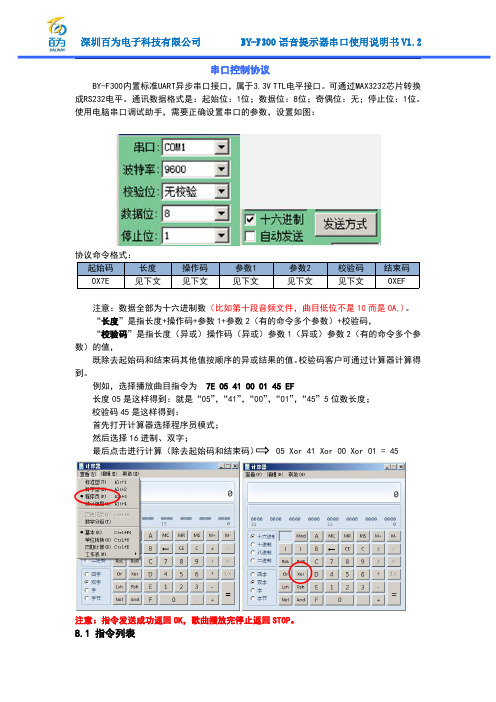
串口控制协议BY-F300内置标准UART异步串口接口,属于3.3V TTL电平接口。
可通过MAX3232芯片转换成RS232电平。
通讯数据格式是:起始位:1位;数据位:8位;奇偶位:无;停止位:1位。
使用电脑串口调试助手,需要正确设置串口的参数,设置如图:注意:数据全部为十六进制数(比如第十段音频文件,曲目低位不是10而是0A,)。
“长度”是指长度+操作码+参数1+参数2(有的命令多个参数)+校验码,“校验码”是指长度(异或)操作码(异或)参数1(异或)参数2(有的命令多个参数)的值,既除去起始码和结束码其他值按顺序的异或结果的值。
校验码客户可通过计算器计算得到。
例如,选择播放曲目指令为7E0541000145EF长度05是这样得到:就是“05”,“41”,“00”,“01”,“45”5位数长度;校验码45是这样得到:首先打开计算器选择程序员模式;然后选择16进制、双字;最后点击进行计算(除去起始码和结束码)05Xor41Xor00Xor01=45注意:指令发送成功返回OK,歌曲播放完停止返回STOP。
8.1指令列表通信控制指令CMD详解对应功能参数(ASCK码)0x01播放无0x02暂停无0x03下一曲无0x04上一曲无0x05音量加无0x06音量减无0x07待机/正常工作无,进入待机状态,电流在10MA0x09复位无0x0A快进无,FLASH无此功能0x0B快退无,FLASH无此功能0x0E停止无CMD详解对应功能参数(8位HEX)0x31设置音量0-30级可调(掉电记忆)0x32设置EQ0-5(NO\POP\ROCK\JAZZ\CLASSIC\BASS)(掉电记忆)0x33设置循环模式0-4(全盘/文件夹/单曲/随机/无循环)0x34文件夹切换0(上一文件夹),1(下一文件夹)0x35设备切换0(U),2(FLASH)CMD详解对应功能参数(16位HEX)0x41选择播放曲目1-255首(掉电记忆)0x42指定文件夹曲目播放高八位为文件夹号(00-99),低八位为歌曲名字(001-255),FLASH无此功能0x43插播功能1-65536,FLASH无此功能0x44插播指定文件夹里面的歌曲高八位为文件夹号(00-99),低八位为歌曲名字(001-255),FLASH无此功能组合播放连续发送不同曲目会播完停止,最大支持10段通信查询命令CMD详解对应功能返回参数(ASCK码)(16位)0x10查询播放状态0(停止)1(播放)2(暂停)3(快进)4(快退) 0x11查询音量大小0-30(掉电记忆)0x12查询当前EQ0-5(NO\POP\ROCK\JAZZ\CLASSIC\BASS(掉电记忆)0x13查询当前播放模式0-4(全盘/文件夹/单曲/随机/无循环)0x14查询版本号 1.00x16查询U盘的总文件总数1-655350x17查询FLASH的总文件数1-2550x18查询当前播放设备0:USB2:SPI0x1A查询U盘的当前曲目1-655360x1B查询FLASH的当前曲目1-2550x1C查询当前播放歌曲的时间反回时间(秒)注意:连续发送两条命令之间间隔在20MS以上,组合播放功能两条命令在6MS以内。
深圳市富满电子集团股份有限公司 FM6808 FM6806 USB充电接口智能控制芯片说明书

FM6808/FM6806(文件编号:S&CIC1441) USB充电接口智能控制芯片概述FM6808/ FM6806是一款USB移动设备充电接口控制芯片,特别的,它采用高通Quick Charge 3.0 A类/B类规范对HVDCP进行自适应充电。
FM6808/ FM6806根据移动设备发送的电压请求能够精确的调整HVDCP输出电压,从而节省最高75%的充电时间。
当移动设备插入USB端口后,FM6808/ FM6806能够自动识别其类型并作出合理相应,从而使得移动设备总能从充电端口获得最大电流。
FM6808/ FM6806支持Apple iPad,Apple iPhone,Samsung Galaxy Note,兼容BC1.2或YD/T 1591标准的设备以及几乎所有的现代移动设备。
FM6808/ FM6806在启动输出电压调整之前会自动检测所连接的受电设备是否兼容QC2.0或者QC3.0协议规范,如果检测到受电设备不兼容QC2.0或者QC3.0协议,FM6808/ FM6806则禁止输出电压调整,仅以5v电压输出以确保旧型USB受电设备能够安全工作。
特点支持Quick Charge3.0的A类和B类规范USB充电接口智能识别:Apple 2.1A/2.4A、Samsung Galaxy Note 2.0A、BC1.2 & YD/T 1591 Battery Charging Specifications4kV ESD-40℃ ~ 125℃工作温度范围输出5V时的功耗低至1mwFM6808封装形式SOP-8;FM6806封装形式SOT23-6应用手机、智能手机、平板和照相机的充电器USB功率输出设备,如移动电源或汽车充电器引脚示意图及说明注:带Pin脚名只用于SOP-8。
FM6808/FM6806(文件编号:S&CIC1441) USB 充电接口智能控制芯片典型应用电路图 FM6808D+D-GNDFM6806D+D-GND订购信息FM6808/FM6806(文件编号:S&CIC1441) USB充电接口智能控制芯片内部功能模块极限工作条件建议器件工作在推荐工作条件以外的情况。
优利德 UDP6900 系列可编程直流电源 说明书

系列可编程直流电源使用说明书REV 22024.2.22感谢您购置优利德数控电源,为了确保正确使用本仪器,在操作仪器之前请仔细阅读手册,特别是有关“安全信息”部分。
如已阅读完手册,建议您将此手册妥善保管,以便在将来使用过程中进行查阅。
UNI-T优利德科技(中国)股份有限公司版权所有。
UNI-T产品受中国或其他国家专利权的保护,包括已取得或正在申请的专利。
本公司保留更改产品规格和价格的权利。
UNI-T保留所有权利。
许可软件产品由UNI-T及其子公司或提供商所有,受国家版权法及国际条约规定的保护。
本文中的信息将取代所有以前出版的资料中的信息。
UNI-T是优利德科技(中国)股份有限公司(Uni-Trend Technology(China) Co., Ltd)的注册商标。
仪器自购买之日起保修期壹年,在保修期内由于使用者操作不当而损坏仪器的,维修费及由于维修所引起的费用由用户承担,仪器由本公司负责终身维修。
如果原购买者自购该产品之日一年内,将该产品出售或转让给第三方,则保修期应为自原购买者从UNI-T或授权的UNI-T分销商购买该产品之日起一年内。
电源线及其他附件和保险丝等不受此保证的保护。
如果在适用的保修期内证明产品有缺陷,UNI-T可自行决定是修复有缺陷的产品且不收部件和人工费用,或用同等产品(由UNI-T决定)更换有缺陷的产品。
UNI-T作保修用途的部件、模块和更换产品可能是全新的,或者经修理具有相当于新产品的性能。
所有更换的部件、模块和产品将成为UNI-T的财产。
以下提到的“客户”是指据声明本保证所规定权利的个人或实体。
为获得本保证承诺的服务,“客户”必须在适用的保修期内向UNI-T通报缺陷,并为服务的履行做适当安排。
客户应负责将有缺陷的产品装箱并运送到UNI-T指定的维修中心,同时预付运费并提供原购买者的购买证明副本。
如果产品要运到UNI-T维修中心所在国范围的地点,UNI-T应支付向客户送返产品的费用。
PSL 693技术说明书_V2.04
国 电 南 自Q/GDNZ.JB41.006-2005标准备案号:2248-2005PSL 693数字式分段保护测控装置技术说明书国电南京自动化股份有限公司GUODIAN NANJING AUTOMATION CO.,LTDPSL 693数字式分段保护测控装置技术说明书编写审核批准V 2.04国电南京自动化股份有限公司2007年09月版本声明本说明书适用于PSL 693数字式分段保护测控装置V2.04及以下版本。
a)软件PSL 693V2.04— CPU模件增加GPS差分输入功能;— 支持双以太网在线升级。
b)硬件PSL 693数字式分段保护测控装置硬件模件版本修改记录表序号 初始版本(2006-11) 第一次修改版本 第二次修改版本1 交流模件 PSL 693-AC.A-A2 CPU模件 PSL 691-CPU.C-A, PSL 691-CPU.C-CPSL 691-CPU.C-D, PSL 691-CPU.C-E3 MMI模件 PSL 691-MMI.A-A4 DIO模件 PSL 691-DIO.A-A5 TRIP模件 PSL 691-TRIP.A-A6 电源模件 PSL 691-PWR.C-A7 母板模件 PSL 691-MB.A-APSL 691数字式线路保护装置产品说明书版本修改记录表1098765432 V2.04 PSL 693程序升级 V2.04 2007.91 V2.03 PSL 693程序初始版本 V2.03 2006.11序号说明书版本号修改摘要软件版本号修改日期* 技术支持 电话:(025)83537262传真:(025)83537200* 本说明书可能会被修改,请注意核对实际产品与说明书的版本是否相符* 2007年9月 第2版 第1次印刷* 国电南自技术部监制I目 录1概述 (1)1.1 保护功能配置 (1)1.2测控功能配置 (1)2技术参数 (1)2.1 保护元件精确工作范围 (1)2.2 保护元件定值误差 (1)2.3 保护整组动作时间 (1)3保护功能及原理 (2)3.1 相间过电流 (2)3.2 零序过电流 (2)3.3 合闸加速 (2)3.4母线充电保护 (2)3.5 控制回路断线 (3)3.6 事故总信号 (3)4端子说明 (4)4.1 交流模件端子X1定义 (4)4.2C PU模件端子X2定义 (4)4.3D IO模件端子X3定义 (5)4.4D IO模件端子X4定义 (5)4.5T RIP模件端子X5定义 (5)4.6 TRIP模件端子X6定义 (6)5定值整定说明 (7)5.1 保护定值清单及说明 (7)5.2 运行参数清单及说明 (8)5.3 软压板清单及说明 (9)6装置信息代码表 (10)6.1 事件信息表 (10)6.2 告警信息表 (10)6.3 软压板信息表 (10)6.4 遥测量信息表 (11)6.5 电量信息表 (11)6.6 遥信量信息表 (11)6.7 遥控量信息表 (12)7装置二次接线示意图 (13)II·概述·1概述PSL 693数字式分段保护测控装置是以电流保护为基本配置,同时集成了各种测量和控制功能的多功能装置,适用于分段断路器的保护及测控。
GE Fanuc RX3i PACSystem IC695ACC302智能辅助电池模块说明说明书
Rx3i PacSystem919-535-3180*******************GE Fanuc IC695ACC302/automation/ge-fanuc/rx3i-pacsystem/IC695ACC302Battery PackPACSystems*IC695ACC302GFK-2592 Auxiliary Smart Battery ModuleMarch 2011The IC695ACC302 Auxiliary Smart Battery Module is an Enhanced version of IC693ACC302. In addition to providing an extended RAM memory backup time compared to that of the standard memory backup batteries (IC698ACC701) for PACSystems CPUs, the smart battery module has a battery monitoring circuit that enables the user to detect the Low Battery state in advance before it is completely drained. The Auxiliary Smart Battery Module replaces the standard CPU RAM backup battery in your control system for the PACSystems CPUs.Pre-installation CheckUpon receiving the battery pack, verify the package contents, which includes the following:▪ IC695ACC302 Auxiliary Smart Battery Module having cable with 4-pin female JAE connector ▪Enabling adapter cable with 4-pin male to 2-pin female connectorDate CodeThe date code is located on the product label on the front of the auxiliary battery module. The date codeconsists of four digits, such as 1011. The first two digits represent the year of manufacture in the 21st century, such as 10 for the year 2010. The last two digits represent the fiscal week of manufacture for the indicated year; for example 11 stands for fiscal week 11.2Auxiliary Smart Battery ModuleGFK-2592Installation1. With power removed from the equipment, drill four #29 (0.136”) holes in the panel mo unting surface, andtap for #8-32 threads, according to the hole pattern shown in the following figure. Use care to keep metal chips from falling into other equipment.2. Securely attach the Smart Battery Module to the panel mounting surface using four #8-32 x ½” flat headmachine screws. 3. While installing the battery to the CPU, first connect the 4-pin Male JAE connector on the enablingadapter cable to the female 4-pin JAE connector on the battery pack as shown in the following figure. (Installing the 4-pin connector enables the battery.).Note1: The battery will begin to drain immediately if attached to the CPU in Power OFF condition. Tomaximize battery life, it is recommended that you install the fresh battery after power has been turned ON to the attached CPU. Note2: Once the enabling adapter cable is connected, the battery starts to drain, even if it is not attached tothe CPU. So, it is recommended to disconnect the enabling adapter cable from the battery pack when the battery is not in use. Even though the discharge current would be negligible with just the enabling adapter cable connected, this can affect Battery life if left in this condition for long durations.Auxiliary Smart Battery Module 3GFK-25924. Connect the 2-pin female connector of the enabling adapter cable to the CPU battery terminals.EXPLOSION WARNING– Do not Install or replace battery pack unless the area is known to be non-hazardous.5. If installed, remove the standard RAM memory backup battery from the system after installing the newauxiliary smart battery module.Note: Refer to the PACSystems CPU Reference Manual, GFK-2222 for details on avoiding loss of PLC RAM memory contents when replacing a RAM memory backup battery. The standard RAM memory backup battery must be removed from the system when using the auxiliary battery module. DiagnosticsNote: Only qualified personnel, who are trained in electrical safety practices and procedures, should perform testing of the IC695ACC302 auxiliary smart battery module. This module is not user-serviceable. TheIC695ACC302 contains a built-in 1-Amp fuse that will open if the unit is subjected to a short-circuit or severe overload condition. This fuse is sealed inside the battery pack and is not replaceable.To test the unit for an open fuse condition:∙Turn off PLC power.∙Unplug the IC695ACC302 auxiliary smart battery module from the CPU.∙Carefully check the auxiliary smart battery module enabling adapter cable connector pins (2 pin Female connector) for presence of voltage (>2.0V) with a DC voltmeter. If the indicated voltage ispresent, the fuse is not open. If no voltage is present, the internal fuse has probably opened and the IC695ACC302 auxiliary smart battery module will have to be replaced.4 Auxiliary Smart Battery Module GFK-2592Safe Handling and DisposalFor Safe handling and d isposal of dead battery modules, reference the manufacturer’s Material Safety Data Sheet (MSDS) and the Battery Disposal Document that are included with this product.CAUTION– Risk of fire, explosion, and burns. Do not short-circuit, crush, incinerate, or disassemble battery.*The nominal backup values are estimated at 20ºC. Backup time increases approximately 17% at 60ºC and decreases approximately 32% at 0ºC.Note:The CPU detects the low battery condition only while the CPU has power. If a low battery condition occurs while the CPU is powered down, the CPU logs a Low Battery fault upon powerup as soon as it detects the signal from the smart battery.However, because the current drain on the battery is negligible with the CPU powered up, logging ofa Low Battery fault is not likely to occur, unless a good battery is replaced with a low battery while theCPU has power. This would indicate to the user that a good battery has been accidentally replaced with a depleted battery.The Battery LED or the fault table indicates the battery status. For details on the operation of specific CPU models, refer to the PACSystems CPU Reference Manual, GFK-2222.Auxiliary Smart Battery Module 5GFK-2592Smart Battery OperationThe battery output voltage is > 2.5 V when the battery is operating in its good state. At the end of the battery good period, the battery output drops to <2.5 V for the battery low state. The period for the battery low state is 15 days for all CPU models. Once battery output voltage drops to <2.5V, the PACSystems CPU detects this as a battery low condition, a Low Battery fault is logged in the CPU fault table and the Battery LED on the CPU starts blinking in red (depending upon the CPU).Once the battery low state is active, the user has 15 days of accumulative battery backed energy left for CPU RAM retention during power loss. If the battery is not replaced within 15 days of accumulative power loss, the CPU RAM memory contents will be lost as the battery output voltage drops to 0V.If the Battery Low condition occurs when the controller is in the Power OFF state, a low battery fault will be logged in the Fault table only at the time when the controller is powered ON. The Battery Low period of 15 days is counted as soon as the Battery Good period is over, but not necessarily when the low battery fault is logged.Consider the following scenario.Controller Power DownBattery GoodThe Battery Low period of 15 days starts at Point A, but the low battery fault is logged only at Point B, once the controller is powered ON. So, the user should make a note that the timestamp of the Low Battery fault may not give the exact start of the 15 days Battery Low period.6 Auxiliary Smart Battery Module GFK-2592The Battery Low indication is not supported on all the PACs CPUs. The table shown below lists the compatible CPU models.Note 1: √- Denotes compatibility of the battery pack with the CPU model.× - Denotes the CPU and battery pack combination is not suitable. (Use of the battery with the CPE030/CRE030 and CPE040/CRE040 is possible, but not recommended due to reduction in battery life as compared toIC693ACC302.)Note2:For CPU320-Fx with CPU Firmware Revisions 6.02 and higher, the battery packs are compatible. The previous revisions of the CPU320 do not support Battery Low detection; hence these new battery packs are notcompatible.Note3:For CRU320-Cx with CPU Firmware Revisions 6.02 and higher the battery packs are compatible. The previous revisions of the CRU320 do not support Battery Low detection; hence these new battery packs are notcompatible.Agency CertificationsThis product is a Listed Accessory for PACSystems Rx3i and Rx7i family of PLC’s and has been evaluated to the following standards for use in ordinary and hazardous areas.∙UL 2054:2004∙ANSI/ISA 12.12.0.1:2007 (UL File E157515)∙EN 60079-0:2006∙EN 60079-15:2005In order to maintain agency certifications this product must be mounted in an enclosure with mechanical impact strength equal or greater than 3.5 Joules.ATEX Marking and InformationII 3 G Ex nA IIC T6 Ta: 0-60C。
Belimo SH24A-MOD200 通信式线性操作器说明书
Communicative linear actuator adjustingdampers and slide valves in technical buildinginstallations• Actuating force 450 N• Nominal voltage AC/DC 24 V• Control modulating, communicative, hybrid • Length of Stroke Max. 200 mm, adjustable in 20 mm increments• Communication via BACnet MS/TP, Modbus RTU, Belimo-MP-Bus or conventional control • Conversion of sensor signalsTechnical dataElectrical dataNominal voltageAC/DC 24 V Nominal voltage frequency 50/60 HzNominal voltage rangeAC 19.2...28.8 V / DC 21.6...28.8 V Power consumption in operation 3.5 W Power consumption in rest position 1.4 W Power consumption for wire sizing 6 VAConnection supply / control Cable 1 m, 6x 0.75 mm²Parallel operationYes (note the performance data)Data bus communicationCommunicative controlBACnet MS/TPModbus RTU (factory setting)MP-BusNumber of nodesBACnet / Modbus see interface description MP-Bus max. 8Functional data Actuating force motor 450 NActuating force variable 25%, 50%, 75% reduziert Operating range Y 2...10 V Input impedance100 kΩOperating range Y variable 0.5...10 V Position feedback U 2...10 V Position feedback U note Max. 0.5 mA Position feedback U variable Start point 0.5...8 V End point 2...10 V Position accuracy ±5%Direction of motion motor selectable with switchDirection of motion note Y = 0 V: with switch 0 (retracted) / 1 (extended)Direction of motion variable electronically reversible Manual override with push-button, can be locked Stroke200 mmLength of Stroke Max. 200 mm, adjustable in 20 mm increments Stroke limitation can be limited on both sides with mechanical end stops Running time motor 150 s / 100 mm Running time motor variable 150...600 s / 100 mm Adaptation setting rangemanualFunctional dataAdaptation setting range variableNo actionAdaptation when switched onAdaptation after pushing the manual override buttonOverride control, controllable via bus communication MAX (maximum position) = 100%MIN (minimum position) = 0%ZS (intermediate position) = 50%Override control variableMAX = (MIN + 32%)...100%MIN = 0%...(MAX – 32%)ZS = MIN...MAX Sound power level, motor52 dB(A)Safety dataProtection class IEC/EN III, Safety Extra-Low Voltage (SELV)Power source ULClass 2 Supply Degree of protection IEC/EN IP54Degree of protection NEMA/UL NEMA 2Enclosure UL Enclosure Type 2EMCCE according to 2014/30/EUCertification IEC/EN IEC/EN 60730-1 and IEC/EN 60730-2-14UL ApprovalcULus according to UL60730-1A, UL60730-2-14 and CAN/CSA E60730-1The UL marking on the actuator depends on the production site, the device is UL-compliant in any caseHygiene test According to VDI 6022 Part 1 / SWKI VA 104-01, cleanable and disinfectable, low emission Type of actionType 1Rated impulse voltage supply / control 0.8 kV Pollution degree 3Ambient humidity Max. 95% RH, non-condensing Ambient temperature -30...50°C [-22...122°F]Storage temperature -40...80°C [-40...176°F]Servicingmaintenance-free WeightWeight 1.2 kgTechnical data•••••••••••Safety notesThis device has been designed for use in stationary heating, ventilation and air-conditioning systems and must not be used outside the specified field of application, especially in aircraft or in any other airborne means of transport.Outdoor application: only possible in case that no (sea) water, snow, ice, insolation or aggressive gases interfere directly with the device and that it is ensured that the ambient conditions remain within the thresholds according to the data sheet at any time.Only authorised specialists may carry out installation. All applicable legal or institutional installation regulations must be complied with during installation.The device may only be opened at the manufacturer's site. It does not contain any parts that can be replaced or repaired by the user.Cables must not be removed from the device.The rotary supports and coupling pieces available as accessories must always be used if transverse forces are likely. In addition, the actuator must not be tightly bolted to the application. It must remain movable via the rotary support (refer to «Installation notes»).If the actuator is exposed to severely contaminated ambient air, appropriate precautions must be taken on the system side. Excessive deposits of dust, soot etc. can prevent the gear rod from being extended and retracted correctly.If not installed horizontally, the maual override button may only be actuated when there is no pressure on the gear rod.To calculate the actuating force required for air dampers and slide valves, the specifications supplied by the damper manufacturers concerning the cross- section and the design, as well as the installation situation and the ventilation conditions must be observed.If a rotary support and/or coupling piece is used, actuation force losses are to be expected.The device contains electrical and electronic components and must not be disposed of as household refuse. All locally valid regulations and requirements must be observed.Mode of operation Converter for sensorsParametrisable actuatorsCombination analogue - communicative(hybrid mode)Simple direct mountingManual override Adjustable strokeProduct featuresThe actuator is fitted with an integrated interface for BACnet MS/TP, Modbus RTU and MP-Bus. It receives the digital control signal from the control system and returns the current status.Connection option for a sensor (passive, active or with switching contact). In this way, the analogue sensor signal can be easily digitised and transferred to the bus systems : BACnet, Modbus or MP-Bus.The factory settings cover the most common applications. Single parameters can be modified with the Belimo service tools MFT-P or ZTH EU.The communication parameters of the bus systems (address, baud rate etc.) are set with the ZTH EU. Pressing the "Address" button on the actuator while connecting the supply voltage resets the communication parameters to the factory setting.Quick addressing: The BACnet and Modbus address can alternatively be set using the buttons on the actuator and selecting 1...16. The selected value is added to the "basic address" parameter and results in the absolute BACnet and Modbus address.With conventional control by means of an analogue control signal, BACnet or Modbus can be used for the communicative position feedbackThe actuator can be directly connected with the application using the enclosed screws. The head of the gear rod is connected to the moving part of the ventilating application individually on the mounting side or with the Z-KS1 coupling piece provided for this purpose.Manual override with push-button possible (the gear train is disengaged for as long as the button is pressed or remains locked).If a stroke limitation will be adjusted, the operating range on this side of the gear rod can be used starting with an extension length of 20 mm and then can be limited respectively in increments of 20 mm by means of the mechanical end stops Z-AS1.High functional reliabilityHome position Adaptation and synchronisation The actuator is overload protected, requires no limit switches in intermediate positions and automatically stops when the end stop is reached (at rest).The first time the supply voltage is switched on, i.e. at the time of commissioning, the actuator carries out a synchronisation. The synchronisation is in the home position (0%).The actuator then moves into the position defined by the control signal.An adaptation can be triggered manually by pressing the "Adaptation" button or with the PC-Tool. Both mechanical end stops are detected during the adaptation (entire setting range). Automatic synchronisation after pressing the manual override button is configured. The synchronisation is in the home position (0%).The actuator then moves into the position defined by the control signal.A range of settings can be adapted using the PC-Tool (see MFT-P documentation)Product featuresAccessoriesMechanical accessories Description TypeEnd stop kit, Multipack 20 pcs.Z-AS1Rotary support, for linear actuator, for compensation of transverse forces Z-DS1Coupling piece M8Z-KS1Tools Description TypeService tool, with ZIP-USB function, for parametrisable andcommunicative Belimo actuators, VAV controller and HVAC performancedevicesZTH EUBelimo PC-Tool, Software for adjustments and diagnostics MFT-PAdapter for Service-Tool ZTH MFT-CConnecting cable 5 m, A: RJ11 6/4 ZTH EU, B: 6-pin for connection toservice socketZK1-GENConnecting cable 5 m, A: RJ11 6/4 ZTH EU, B: free wire end for connectionto MP/PP terminalZK2-GENWire colours:1 = black2 = red3 = white5 = orange6 = pink7 = grey Functions:C1 = D- = A (wire 6) C2 = D+ = B (wire 7)Electrical installationSupply from isolating transformer.The wiring of the line for BACnet MS/TP / Modbus RTU is to be carried out in accordance withapplicable RS-485 regulations.Modbus / BACnet: Supply and communication are not galvanically isolated. Connect earth signalof the devices with one another.Wiring diagramsBACnet MS/TP / Modbus RTUElectrical installationFunctionsFunctions with specific parameters (Parametrisation necessary)Modbus RTU / BACnet MS/TP with analogue setpoint (hybrid mode)Connection with active sensor, e.g. 0...10 V @ 0...50°CPossible input voltage range: 0...10 VResolution 30 mVConnection with switching contact, e.g. Δp monitorSwitching contact requirements: The switching contact must be able to switch a current of 16 mA at 24 V accurately.Start point of the operating range must be parametrised on the MOD actuator as ≥0.5 V.Functions with specific parameters (Parametrisation necessary)Connection with passive sensor, e.g. Pt1000, Ni1000, NTC1) depending on type2) Resolution 1 OhmCompensation of the measuredvalue is recommendedMP-BusMP-Bus Network topologyThere are no restrictions for thenetwork topology (star, ring,tree or mixed forms arepermitted).Supply and communication inone and the same 3-wire cable• no shielding or twistingnecessary• no terminating resistorsrequiredFunctionsOperating controls and indicators1Direction of stroke switch Switch over:Direction of stroke changes2Push-button and LED display green Off:No power supply or malfunction On:In operationFlashing:In address mode: Pulses according to set address (1...16)When starting: Reset to factory setting (Communication)Press button:In standard mode: Triggers stroke adaptationIn address mode: Confirmation of set address (1...16)3Push-button and LED display yellow Off:Standard modeOn:Adaptation or synchronisation process activeor actuator in address mode (LED display green flashing)Flickering:BACnet / Modbus communication activePress button:In operation (>3 s): Switch address mode on and offIn address mode: Address setting by pressing several times When starting (>5 s): Reset to factory setting (Communication)4Manual override button Press button:Gear train disengages, motor stops, manual override possible Release button:Gear train engages, synchronisation starts, followed by standard mode5Service plugFor connecting parametrisation and service tools Check power supply connection 2 Off and 3 OnPossible wiring error in power supplyApplications without transverse forcesApplications with transverse forcesInstallation notesIf a rotary support and/or coupling piece is used, losses in the actuation force losses are to be expected.The linear actuator is screwed directly to the housing at three points. Afterwards, the head of the gear rod is fastened to the moving part of the ventilation application (e.g. damper or slide valve).The coupling piece with the internal thread (Z-KS1) is connected to the head of the gear rod. The rotary support (Z-DS1) is screwed to the ventilation application. Afterwards, the linear actuator is screwed to the previously mounted rotary support with the enclosed screw. Afterwards, the coupling piece, which is mounted to the head of the gear rod, is attached to the moving part of the ventilating application (e.g. damper or slide valve). The transverse forces can becompensated for to a certain limit with the rotary support and/or coupling piece. The maximum permissible swivel angle of the rotary support and coupling piece is 10° (angle), laterally and upwards.Quick addressingTool connection Service1. Press the "Address" button until the green "Power" LED is no longer illuminated. The green "Power" LED flashes in accordance with the previously set address.2. Set the address by pressing the "Address" button the corresponding number of times (1...16).3. The green LED flashes in accordance with the address that has been entered (1...16). If the address is not correct, it can be reset in accordance with step 2.4. Confirm the address setting by pressing the green "Adaptation" button.If the address is not confirmed within 60 seconds, the address procedure will be ended. Any address change that has already been started will be discarded.The resulting BACnet MS/TP and Modbus RTU address is made up of the set basic address plus the short address (e.g. 100+7=107).The actuator can be parametrised by ZTH EU via the service socket.For an extended parametrisation the PC tool can be connected.Connection ZTH EU / PC-ToolDimensionsFurther documentation• Tool connections• BACnet Interface description• Modbus Interface description• Overview MP Cooperation Partners• MP Glossary• Introduction to MP-Bus TechnologyApplication notes• For digital control of actuators in VAV applications patent EP 3163399 must be considered.。
TOF200、TOF201 多点 TOF 测距 通信协议指令说明说明书
类别 内容关键词 TOF20x 、UART 、指令 摘要TOF20x 通信协议指令说明TN01010101 1.0.1 Date:2023/3/20TOF20x多点TOF 测距©2023 Guangzhou ZLG Technology Corp.,Ltd.修订历史版本日期原因V1.0.00 2022/08/25 创建文档V1.0.1 2023/3/20 更改名称描述目录1. 功能简介 (2)2. 交互指令 (3)2.1命令帧数据格式 (3)2.2通信协议概述 (3)3. 应用指南 (5)3.1获取信息 (5)3.1.1获取ID (5)3.1.2获产品版本号 (5)3.1.3获取状态 (5)3.1.4获取测距结果 (6)3.1.5获取模块串扰值 (6)3.2设置参数 (7)3.2.1初始化 (7)3.2.2启动测距 (7)3.2.3停止测距 (8)3.2.4执行校准 (8)3.2.5设置测量周期 (8)3.2.6设置迭代次数 (8)3.2.7设置SPAD_MAP_ID (9)3.2.8设置置信度阈值 (9)3.2.9设置8×8模式 (9)3.3设置系统参数 (10)3.3.1进入睡眠模式 (10)3.3.2使能自动输出 (10)3.3.3禁能自动输出 (10)3.3.4设置进入测试模式 (10)3.3.5设置退出测试模式 (11)3.3.6设置波特率 (11)3.4常规调试流程 (11)4. 免责声明 (14)1. 功能简介2D-ToF多点高精度测距方案集成了ToF传感器芯片,MCU主控和电源管理,对外采用5pin接口,与主机串口指令通信,方便易用可快速上手。
具有测距远和精度高的特点,有效测距距离是1~500cm,测距精度可达±3%,可广泛应用于测控、工业、医疗、消费类电子产品等需要检测距离的领域。
TOF20x的主要特征如下:工作电压范围:3.3/5V;抵抗环境光干扰能力强;有效识别距离:1~500cm;测距精度可达±3%;UART命令帧通信协议;多点dToF技术;检测区域:3×3、4×4、3×6、8×8。
- 1、下载文档前请自行甄别文档内容的完整性,平台不提供额外的编辑、内容补充、找答案等附加服务。
- 2、"仅部分预览"的文档,不可在线预览部分如存在完整性等问题,可反馈申请退款(可完整预览的文档不适用该条件!)。
- 3、如文档侵犯您的权益,请联系客服反馈,我们会尽快为您处理(人工客服工作时间:9:00-18:30)。
BF693xA通信协议说明
摘要
BF693xA芯片对触控屏上电容值进行采样,通过比较电容值的变化值判断触摸状态,并经过算法实现触摸点的定位。
算法检测出最多10个点的触摸状态并得到精确的触摸点坐标,用户可以通过坐标信息进行相关的人机界面操作。
关键词:电容检测、IIC、通信协议
文件发行/修订履历
目录
摘要 (1)
一.功能及特点 (4)
二.IIC总线规则 (5)
2.1 IIC总线时序 (5)
2.2 IIC协议 (5)
2.2.1 IIC写流程 (5)
2.2.2 IIC读流程 (6)
2.3寄存器列表及说明 (7)
2.3.1 寄存器列表 (7)
2.3.2 寄存器说明 (9)
2.3.3 注意事项 (10)
一.功能及特点
主要功能特点:
1、BF693xA 采用iic 协议与HOST 通信,支持7位的寻址方式,从机地址7位为0x2c ,8位为0x58;
2、iic 传输速率:100Kbps ,400Kbps
3、中断触发机制,电容屏TP 被触摸时产生一个中断信号DAV ,该信号低电平有效;
4、帧频60~80;
5、通信系统连接图如下图1-1所示:
图1-1 通信系统连接图
6、连接HOST
端6个引脚:
● GND:芯片地引脚 ● VCC:芯片电源引脚
● DAV/PGD:触摸中断标志/烧录数据引脚 ● SDA/PGC:IIC 数据引脚/烧录时钟引脚 ● SCL/PRO:IIC 时钟引脚/烧录使能引脚 ● RST:复位引脚,调试、烧录不需要接线
二.IIC 总线规则
2.1 IIC 总线时序
图2-1 IIC 总线时序
开始条件START :当IIC 时钟SCL 为高,数据SDA 由高变低。
停止条件STOP :当IIC 时钟SCL 为高,数据SDA 由低变高。
数据稳定期:当时钟SCL 为高时,数据保持不变。
数据变更期:当时钟SCL 为低时,数据进行更改。
当触摸TP 时,DAV 信号由高到低,HOST 和TP 之间开始进行通信,当HOST 发起读坐标通信时,DAV 信号随即置为高电平。
DAV 的周期不是固定不变的,它取决于HOST 的通信速度以及TP 的各项参数。
2.2 IIC 协议 2.2.1 IIC 写流程
HOST 可以根据寄存器列表对相关寄存器进行写操作,时序图如图2-2所示:
From master to slave From slave to master A:acknowledge(SDALOW)
N:notacknowledge(SDAHIGH)
S:START P:STOP
图2-2 IIC write
2.2.2 IIC 读流程
HOST 可以根据寄存器列表对相关寄存器进行读操作,时序图如图2-3所示:
From master to slave From slave to master A:acknowledge(SDALOW)N:notacknowledge(SDAHIGH)S:START
P:STOP
图2-3 IIC read
2.3寄存器列表及说明2.
3.1 寄存器列表
2.3.2 寄存器说明
1、Operation mode:配置该寄存器可实现以下功能
●休眠模式:当对寄存器(0x07)写入0x00时TP进入休眠模式,芯片将停止工作,以
降低功耗。
●唤醒:对寄存器(0x07)写入0x01,将TP唤醒。
●获取版本号:对寄存器(0x07)写入0x44读取TP的版本号,TP会发送6个字节的
版本号
2、FTHD_H、FTHD_L
●手指阈值修改:开机配置时对TP的寄存器(0x08)连续写入手指阈值的高8位和低8
位,TP将把高低位组合赋给手指阈值,手指阈值范围150~350,HOST写操作如下START->(设备地址+写)->寄存器地址0x08-> FTHD_H -> FTHD_L->STOP
●手指阈值读取:HOST读操作如下
START->(设备地址+写)->寄存器地址0x08->RESTART->(设备地址+读)-> FTHD_H -> FTHD_L->STOP
3、NTHD_H、NTHD_L
●噪声阈值修改:开机配置时对TP的寄存器(0x0a)连续写入噪声阈值的高8位和低8
位,TP将把高低位组合赋给噪声阈值,噪声阈值范围50~200,HOST写操作如下
START->(设备地址+写)->寄存器地址0x0a-> NTHD_H -> NTHD_L->STOP
●噪声阈值读取:HOST读操作如下
START->(设备地址+写)->寄存器地址0x0a->RESTART->(设备地址+读)-> NTHD_H -> NTHD_L->STOP
4、RESX_H、RESX_L、RESY_H、RESY_L
●分辨率X/Y修改:开机配置时对TP的寄存器(0x0c/0x0e)连续写入分辨率X/Y的高
8位和低8位,TP将把高低位组合赋给分辨率X/Y,写操作参照手指阈值修改,只有寄存器地址不同。
●分辨率X/Y读取:读操作参照手指阈值读取,只有寄存器地址不同。
5、TOUCH:表示触摸点数,无触摸为0x80,单点触摸为0x81,两点触摸为0x82,三点触摸为0x83,以此类推;无触摸时寄存器0x5d-0x84数据全为0。
6、X1_H~ X10_H、X1_L~ X10_L、Y1_H~ Y10_H、Y1_L~ Y10_L
坐标X,Y的高低8位,其中包含了触摸ID号和触摸状态的信息
●Touch state:包含三种手指触摸状态,第一次触摸,保持触摸,抬起。
表2-1 触摸状态
●Touch ID按如下规则定义:
最先按下的触摸点ID为1,后依次增加,最大到10。
当有触摸点抬起时,不影响其他触摸点ID。
同一个触摸点的数据并不是固定在同一个寄存器中,靠后的触摸点在其他触摸点抬起时,在寄存器中的位置会往前移动。
例如:当有2个手指触摸时,第一个手指触摸点ID为1,数据放在0x5d-0x60寄存器中,第二个手指触摸点ID为2,数据放在0x61-0x64寄存器中。
当第一个手指抬起后,第二个手指仍然触摸,此时第二个手指触摸点ID依然是2,触摸点数T ouchnum仍为2,寄存器0x5d-0x60仍保留第一个手指的ID号为1,Touchstate为抬起,HOST读完这帧数据后下一帧数据的触摸点数即变成1,第二个手指触摸数据位置相应往前移动到0x5d-0x60寄存器中,原先存放位置0x61-0x64寄存器清零。
这时如果再有一个手指触摸,数据放置在0x61-0x64寄存器中。
●读取坐标流程如下
START->(设备地址+写)->寄存器地址0x5c->RESTART->(设备地址+读)-> 连续读取坐标信息->STOP
2.3.3 注意事项
1、按照实际应用设置分辨率X、Y。
2、芯片上电初始化需要100ms,由休眠唤醒到稳定工作需要20ms,建议HOST操作过程中请预留足够的时间。
3、上电时HOST可根据需要读取版本号,每发一次指令读一次。
4、中断信号DAV开机时为高电平,无触摸时也为高,有触摸后置为低电平,HOST发起读通信置为高电平,若不来读则一直为低。
5、建议HOST检测到DAV信号为低电平时能立即读取数据,如果延时太长,TP已经更新坐标信息,就会造成HOST读到的数据有误或丢失数据。
HOST可以按照读到的触摸点数来决定后面读取数据的长度,也可以一次读完所有坐标信息。